Sign In
Upload
Download
Table of Contents
Contents
Add to my manuals
Delete from my manuals
Share
URL of this page:
HTML Link:
Bookmark this page
Add
Manual will be automatically added to "My Manuals"
Print this page
×
Bookmark added
×
Added to my manuals
Manuals
Brands
Supermicro Manuals
Motherboard
X11SCM-LN8F
User manual
Supermicro X11SCM-LN8F User Manual
Hide thumbs
1
2
3
4
Table Of Contents
5
6
7
8
9
10
11
12
13
14
15
16
17
18
19
20
21
22
23
24
25
26
27
28
29
30
31
32
33
34
35
36
37
38
39
40
41
42
43
44
45
46
47
48
49
50
51
52
53
54
55
56
57
58
59
60
61
62
63
64
65
66
67
68
69
70
71
72
73
74
75
76
77
78
79
80
81
82
83
84
85
86
87
88
89
90
91
92
93
94
95
96
97
98
99
100
101
102
103
104
105
106
107
108
109
110
111
112
113
114
115
116
117
118
119
page
of
119
Go
/
119
Contents
Table of Contents
Troubleshooting
Bookmarks
Table of Contents
Table of Contents
Checklist
Quick Reference
Quick Reference Table
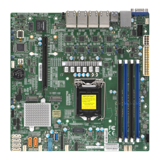
Motherboard Features
Processor and Chipset Overview
Recovery from AC Power Loss
Special Features
ACPI Features
Environmental Temperature Control
Fan Status Monitor with Firmware Control
Onboard Voltage Monitors
System Health Monitoring
System Resource Alert
Power Supply
Serial Port
Chapter 2 Installation
Static-Sensitive Devices
Precautions
Unpacking
Motherboard Installation
Tools Needed
Location of Mounting Holes
Installing the Motherboard
Processor and Heatsink Installation
Installing the LGA 1151 Processor
Installing an Active CPU Heatsink with Fan
Removing the Heatsink
Memory Support and Installation
Memory Support
General Guidelines for Optimizing Memory Performance
DIMM Installation
DIMM Removal
Rear I/O Ports
Front Control Panel
Connectors
Power Connections
Headers
Jumper Settings
How Jumpers Work
LED Indicators
Chapter 3 Troubleshooting
Troubleshooting Procedures
Before Power on
No Power
No Video
System Boot Failure
Memory Errors
Losing the System's Setup Configuration
When the System Becomes Unstable
Technical Support Procedures
Frequently Asked Questions
Battery Removal and Installation
Battery Removal
Proper Battery Disposal
Battery Installation
Returning Merchandise for Service
Chapter 4 BIOS
Introduction
Main Setup
Advanced Setup Configurations
Event Logs
Ipmi
Security
Boot
Save & Exit
Appendix A BIOS Codes
BIOS Error POST (Beep) Codes
Appendix B Software Installation
Installing Software Programs
Superdoctor ® 5
Appendix C Standardized Warning Statements
Appendix D UEFI BIOS Recovery
Overview
Recovering the UEFI BIOS Image
Recovering the Main BIOS Block with a USB Device
Advertisement
Quick Links
Download this manual
Questo manuale d'istruzione è fornito da trovaprezzi.it. Scopri tutte le offerte per
Supermicro X11SCL-
LN4F
o cerca il tuo prodotto tra le
migliori offerte di Schede Madri
X11SCM-LN8F
X11SCM-F
X11SCL-LN4F
USER'S MANUAL
Revision 1.1
Table of
Contents
Previous
Page
Next
Page
1
2
3
4
5
Advertisement
Table of Contents
Need help?
Do you have a question about the X11SCM-LN8F and is the answer not in the manual?
Ask a question
Questions and answers
Related Manuals for Supermicro X11SCM-LN8F
Motherboard Supermicro X11SCA Quick Reference Manual
(25 pages)
Motherboard Supermicro X11SCA User Manual
(113 pages)
Motherboard Supermicro X11SCQ-L User Manual
(122 pages)
Motherboard Supermicro X11SCZ-F/Q User Manual
(129 pages)
Motherboard Supermicro X11SCE-F User Manual
(95 pages)
Motherboard Supermicro X11SCD-F User Manual
(111 pages)
Motherboard Supermicro X11SCW-F User Manual
(118 pages)
Motherboard Supermicro X11SCL-F User Manual
(117 pages)
Motherboard Supermicro X11SCV-Q User Manual
(116 pages)
Motherboard Supermicro X11SCV-L User Manual
(116 pages)
Motherboard Supermicro X11SCL-IF User Manual
(117 pages)
Motherboard Supermicro X11SCH-F User Manual
(119 pages)
Motherboard Supermicro X11SCH-LN4F User Manual
(119 pages)
Motherboard Supermicro X11SCH-LN4F-O User Manual
(119 pages)
Motherboard Supermicro X11SCM-F User Manual
(119 pages)
Motherboard Supermicro X11SCL-LN4F User Manual
(119 pages)
This manual is also suitable for:
X11scm-f
X11scl-ln4f
Table of Contents
Print
Rename the bookmark
Delete bookmark?
Delete from my manuals?
Login
Sign In
OR
Sign in with Facebook
Sign in with Google
Upload manual
Upload from disk
Upload from URL


Need help?
Do you have a question about the X11SCM-LN8F and is the answer not in the manual?
Questions and answers