
Related Manuals for Supermicro X11SPA-TF


Summary of Contents for Supermicro X11SPA-TF
- Page 1 X11SPA-TF X11SPA-T ENGLISH 繁體中文 简体中文 日本語 한국어 QUICK REFERENCE GUIDE Revision 1.0b...
-
Page 2: About Standardized Warning Statements
Should you have questions or experience difficulty, contact Supermicro's Technical Support Department for assistance. Only certified technicians should attempt to install or configure components. Read this section in its entirety before installing or configuring components in the Supermicro chassis. WARNING: This product can expose you to chemicals including lead, known to the State of California to cause cancer and birth defects or other reproductive harm. - Page 3 X11SPA-TF/X11SPA-T QUICK REFERENCE GUIDE 限用物質含有情況標示聲明書 限用物質含有情況標示聲明書 Declaration of the Presence Condition of the Restricted Substances Marking 設備名稱:主機板 / Motherboard , 型號(型式): X11SPA-TF, X11SPA-T Type designation (Type) Equipment name 限用物質及其化學符號 Restricted substances and its chemical symbols 六價鉻 多溴聯苯 多溴二苯醚 單元 Unit...
-
Page 4: Ami Bios Post Codes
X11SPA-TF/X11SPA-T QUICK REFERENCE GUIDE BIOS POST Codes AMI BIOS POST Codes About AMI BIOS POST Codes The table below lists some of AMI BIOS POST codes for X11SPA-TF/X11SPA-T. For more information, refer to https:// www.supermicro.com/manuals/other/AMI_AptioV_BIOS_POST_Codes_for_SM_Motherboards.pdf. Code Description 0x32 CPU post-memory initialization is started... -
Page 5: Ssd Installation
X11SPA-TF/X11SPA-T QUICK REFERENCE GUIDE M.2 SSD Installation Instructions M.2 SSD Installation Instructions M.2 SSD Installation Warning: Be sure to install the M.2 SSD(s) prior to placing a motherboard into a chassis. Please refer to the M.2 SSD installation and removal instructions as shown below and on the next page for proper procedures. - Page 6 X11SPA-TF/X11SPA-T QUICK REFERENCE GUIDE M.2 SSD Removal Instructions M.2 SSD Removal Instructions M.2 SSD Removal Note: The position of the standoff can be adjusted slightly to fit your M.2 SSD if needed. (Refer to the FAQ on the Supermicro website at https://www.supermicro.com/support/faqs/faq.cfm?faq=30404.) Unscrew the existing mounting screws Gently lift the M.2 SSD and be careful...
-
Page 7: Memory Population
X11SPA-TF/X11SPA-T QUICK REFERENCE GUIDE Memory Population Memory Population Note: Unbalanced memory configuration decreases memory performance and is not recommended for Supermicro motherboards. DCPMM (Intel Optane™ DC Persistent Memory Modules) Population Tables for the X11SPA-TF/ X11SPA-T (w/12 Slots) based on the 82xx/62xx/52xx/42xx Platform... - Page 8 X11SPA-TF/X11SPA-T QUICK REFERENCE GUIDE Notification for the Mounting Holes Notification for the Mounting Holes Note: Before assembling the motherboard, pay attention to the location of mounting holes. Please select the chassis which fits the mounting hole locations of this motherboard. Refer to the illustration below for the location details.
- Page 9 X11SPA-TF/X11SPA-T QUICK REFERENCE GUIDE Notes Notes...
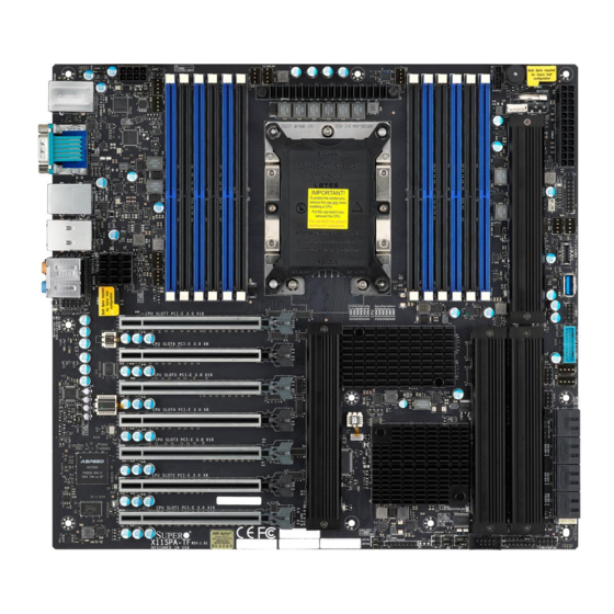
- Page 10 UPERMICR X11SPA-TF/X11SPA-T . 1.0b uick efeRence uide Motherboard Layout and Features I/O BACK PANEL Universal ID UID-LED UID-SW JPAC1 JSPDIF_OUT AUDIO FP ASPEED HD AUDIO JPUSB1 AST2500 COM1 JPWR4 USB8/9 (3.1) USB4/5(3.0) USB6/7 (3.0) USB3.1 Gen.2 USB3.1 Gen.1 USB3.1 Gen.1...
-
Page 11: Jumpers And Connectors
*The initial system fan speed must not be lower than 600 RPM. HD AUDIO Back Panel High Definition Audio Dedicated IPMI LAN Port IPMI_LAN *For IPMI support, X11SPA-TF is via SPS, whereas X11SPA-T is via ME. I-SATA0~7 Intel Serial ATA (SATA 3.0) Ports 0~7 (6Gb/sec) I-SGPIO1/I-SGPIO2 Serial General Purpose I/O Headers... -
Page 12: Led Indicators
(1DPC and 2DPC are recommended for memory installation. Only selected 2nd Gen Intel Xeon Scalable-SP processors support Intel Optane™ DC Persistent Memory Modules.) Notes: 1) For memory optimization, use only DIMM modules that have been validated by Supermicro. For the latest memory updates, please refer to our website at http://www.supermicro.com/products/motherboard. -
Page 13: Back Panel I/O Connectors
I. 10Gb RJ45 Port 2 O. Line In D. COM1 Port J. USB 3.1 Gen1 Port 5 P. Line Out E. VGA Port K. USB 3.1 Gen1 Port 4 Q. Mic In F. Dedicated IPMI LAN Port L. Center/LFE Out R. UID Switch X11SPA-TF/-T... - Page 14 UPERMICR 美超微電腦股份有限公司 X11SPA-TF/X11SPA-T 快速參考指南版本1.0b 主機板元件配置圖 I/O BACK PANEL Universal ID UID-LED UID-SW JPAC1 AUDIO FP JSPDIF_OUT ASPEED HD AUDIO JPUSB1 AST2500 COM1 JPWR4 USB8/9 (3.1) USB4/5(3.0) USB6/7 (3.0) USB3.1 Gen.2 USB3.1 Gen.1 USB3.1 Gen.1 LAN1 LAN2 IPMI_LAN LEDBMC JPL1 JPL2...
- Page 15 單一主機板包裝盒內容清單 • Supermicro主機板 x1 • 快速參考指南 • SATA訊號線 x6 • GPU轉CPU電源線 x1 • 後檔板 x1 跳線器/連接埠 跳線器 (Jumper) 跳線器 說明 預設值 J9701/J9702 工廠製造設定模式 針腳1-2(正常) JPAC1 啟用/停用音源 針腳1-2(啟用) JPG1 啟用/停用VGA 針腳1-2(啟用) JPL1/JPL2 啟用/停用LAN1/LAN2 針腳1-2(啟用) JPME2 Intel製造模式 針腳1-2(正常) JWD1 啟動系統監控(Watch Dog)功能 針腳1-2(重設)...
- Page 16 M.2指示燈 綠燈閃爍:M.2使用中 LEDBMC BMC運作指示燈 綠燈閃爍:BMC正常 LEDPWR 內建電源指示燈 綠燈恆亮:開啟 UID-LED 單位識別指示燈 藍燈恆亮:識別中 中央處理器和記憶體支援 本主機板 X11SPA-TF/X11SPA-T 支援 Intel® Xeon® Scalable-SP系列和第二代Intel Xeon Scalable-SP系列 處理器。記憶 體支援 Unbuffered(UDIMM)ECC/Non-ECC DDR4 ,容量最高可達 768GB ECC RDIMM , 3TB 3DS RDIMM , 1.5TB LRDIMM , 和3TB 3DS LRDIMM DDR4 , 及十二個傳輸頻率最高可達2933MHz ( 2DPC )...
- Page 17 備註 • 快速參考指南中的圖例僅供安裝及操作說明使用,可能與實際產品外觀不同。 • 欲知更多跳線器/連接埠/指示燈/記憶體/主機板/中央處理器的安裝相關資訊,請參閱 X11SpA-TF/X11SpA-T使用手冊》第二章。 《S upermicro 中央處理器與散熱器安裝方式 依照下方圖示及說明將CPU安裝至處理器固定板上。 安裝好處理器散熱模組後,將處理器散熱模組裝在主機板的CPU CPU反面 (CPU LGA 針腳面朝上) 將CPU上的B點對齊 插槽之上。使用六星型螺絲起子,慢慢依序將四個螺絲拴入安裝 處理器固定板上的B點 孔#1-4中。 針腳 1 橢圓形C孔 將CPU上的A點對齊 處理器固定板上的A點 處理器固定板 (反面) 對齊CPU針腳 1 橢圓形D孔 大導柱 安裝處理器散熱模組時,將安裝好的CPU固定板置於 使用六星型螺絲起子 散熱器之上。 CPU上的三角形 小導柱 三角圖示 安裝處理器的散熱模組於CPU插槽上 依照順序栓緊螺絲 #1, 2, 3, 4 處理器固定板上的三角形...
- Page 18 UPERMICR 美超微电脑股份有限公司 X11SPA-TF/X11SPA-T 快速参考指南版本1.0b 主板元件配置图 I/O BACK PANEL Universal ID UID-LED UID-SW JPAC1 AUDIO FP JSPDIF_OUT ASPEED HD AUDIO JPUSB1 AST2500 COM1 JPWR4 USB8/9 (3.1) USB4/5(3.0) USB6/7 (3.0) USB3.1 Gen.2 USB3.1 Gen.1 USB3.1 Gen.1 LAN1 LAN2 IPMI_LAN LEDBMC JPL1 JPL2...
- Page 19 单一主板包装盒內容清单 • Supermicro主板 x1 • 快速参考指南 • SATA数据线 x6 • GPU转CPU电源线 • 后挡板 x1 跳帽/接口 跳帽(Jumper) 跳帽 说明 预设值 J9701/J9702 工厂制造设置模式 针脚1-2(正常) JPAC1 启用/停用音源 针脚1-2(启用) JPG1 启用/停用VGA 针脚1-2(启用) JPL1/JPL2 启用/停用LAN1/LAN2 针脚1-2(启用) JPME2 针脚1-2(正常) Intel制造模式 JWD1 启用看门狗(Watch Dog)功能 针脚1-2(重启) 接口(Connector) 接口...
- Page 20 绿灯闪烁:BMC正常 BMC心跳指示灯 LEDPWR 內建电源指示灯 绿灯恒亮:开启 UID-LED 系统识别指示灯 蓝灯恒亮:识别中 中央处理器和内存支持 本主板 X11SPA-TF/ X11SPA-T 支 持 Intel®Xeon®Scalable - SP系 列和 第二代Intel Xeon Scalable - SP系 列处 理 器。内存支持 ,容量最高可达 , Unbuf fered(UDIMM)ECC/Non- ECC DDR4 768GB ECC RDIMM 3TB 3DS , , 和3TB 3DS LRDIMM DDR4 , 及十二个传输频率最高可达 2933MHz (2DPC)288 RDIMM 1.5TB LRDIMM...
- Page 21 备注 • 快速参考指南中的图例仅供安装及操作说明使用,可能与实际产品外观不同。 • 欲知更多跳帽/接口/指示灯/内存/主板/中央处理器的安装相关资讯,请参阅 X11SpA-TF/X11SpA-T使用手冊》第二章。 《S upermicro 中央处理器与散热器安装方式 依照下方图示及说明将CPU安装至处理器固定板上。 CPU反面 (CPU LGA 针脚面朝上) 将CPU上的B点对齐 安装好处理器散热模组后,将处理器散热模组装在主机板的CPU插 处理器固定板上的B点 槽之上。使用六星型螺丝起子,慢慢依1,2,3,4顺序将四个螺丝 旋入安装孔#1-4中。 针脚 1 椭圆形C孔 将CPU上的A点对齐 处理器固定板上的A点 处理器固定板 (反面) 对齐CPU针脚 1 椭圆形D孔 大导柱 安装处理器散热模组时,将安装好的CPU固定板置于 使用六星型螺丝起子 散热器之上。 CPU上的三角形 小导柱 三角图示 安装处理器的散热模组于CPU插槽上 依照顺序栓紧螺丝 #1, 2, 3, 4 (主板上)
- Page 22 UPERMICR X11SPA-TF/X11SPA-T 1.0b マザーボードの配置および機能 I/O背面パネル Universal ID UID-LED UID-SW JPAC1 JSPDIF_OUT AUDIO FP ASPEED HD AUDIO JPUSB1 AST2500 COM1 JPWR4 USB8/9 (3.1) USB4/5(3.0) USB6/7 (3.0) USB3.1 Gen.2 USB3.1 Gen.1 USB3.1 Gen.1 LAN1 IPMI_LAN LAN2 LEDBMC JPL1 JPL2 DIMMC1 FAN D...
- Page 23 パッケージ内容 • クイックレファレンガイド x1 • Supermicroマザーボード x1 • SATAケーブル x6 • GPU-CPU電源ケーブル x1 • I/Oシールド x1 ジャンパーおよびコネクタ ジャンパー ジャンパー 説明 デフォルト J9701/J9702 製造モード ピン1~2(通常) JPAC1 音声有効/無効 ピン1~2(有効) ピン1~2(有効) JPG1 VGA有効/無効 ピン1~2(有効) JPL1/JPL2 LAN1/LAN2有効/無効 JPME2 Intel製造モード ピン1~2(通常) ウォッチドッグ機能有効 ピン1~2(RST) JWD1 コネクタ...
- Page 24 緑色に点滅:デバイスの動作 LEDBMC BMC Heartbeat LED 緑色に点滅:BMCノーマル LEDPWR 基板上の電源LED 緑色に点灯:電源オン UID-LED ユニット識別子(UID)LED 青色点灯:単位識別済み 対応CPUとメモリ 対応CPUとメモリ マザーボードX11SPA-TF / X11SPA-Tは、Intel® Xeon® Scalable-SPシリーズおよびIntelの第2世代Xeon Scalable-SPシリーズ プロセッサをサポートしています。最大768GBのECC RDIMM、3TBの3DS RDIMM、1.5TBのLRDIMM 、12個のメモリスロットに最 大2933MHz(2DPC)の速度を備えた3TBの3DS LRDIMM DDR4(288ピン)ECCメモリをサポートします。これらのDIMMスロッ トに同じタイプとサイズの一組のメモリモジュールを取り付けると、メモリがインターリーブされ、メモリのパフォーマンスが向上します。(メモリの 取り付けには、1DPCと2DPCをお勧めします。選択されたIntelの第2世代Xeon Scalable-SPプロセッサのみがIntel Optane™ DC Persistentメモリをサポートします。) DIMMメモリの取り付け CPU側 DIMMD2(黒スロット) DIMMD1(青スロット) DIMME2(黒スロット) DIMME1(青スロット) DIMMF2(黒スロット)...
- Page 25 Ground SW_NMI_N 接地 SW_NMI_N 背面パネルI/Oコネクタ A.1Gb RJ45ポート1 G.USB 3.1 Gen1ポート7 M.サラウンド出力 B.USB 3.1 Gen2ポート9 H.USB 3.1 Gen1ポート6 N.S/PDIF出力 C.USB 3.1 Gen2ポート8(タイプC) I.10Gb RJ45ポート2 O.ライン入力 D.COM1ポート J.USB 3.1 Gen1ポート5 P. ライン出力 E.VGAポート K.USB 3.1 Gen1ポート4 Q.マイク入力 F.専用IPMI LANポート L.センター/LFE出力 R.UIDスイッチ X11SPA-TF/-T...
- Page 26 UPERMICR X11SPA-TF/X11SPA-T 간편 참조서 개정판 1.0b 간편 참조서 개정판 메인보드 레이아웃 및 특징 메인보드 레이아웃 및 특징 I/O BACK PANEL I/O BACK PANEL Universal ID UID-LED UID-SW JPAC1 JSPDIF_OUT AUDIO FP ASPEED HD AUDIO JPUSB1 AST2500 COM1 JPWR4 USB8/9 (3.1) USB4/5(3.0)
- Page 27 *시스템 팬의 초기 속도 는 600 RPM 이상이어야 합니다 HD AUDIO 후면 패널 고화질 오디오 전용 IPMI LAN 포트 IPMI_LAN *X11SPA-TF의 BIOS 펌웨어는 SPS이며, X11SPA-T의 BIOS 펌웨어는 ME입니다 I-SATA0~7 Intel 시리얼 ATA (SATA 3.0) 포트 0~7 (6Gb/초) I-SGPIO1/I-SGPIO2 연속 범용 I/O 헤더...
- Page 28 여 메모리 성능이 향상됩니다. (1DPC 및 2DPC의 경우 메모리를 설치하는 것이 좋습니다. 선택된 Intel의 2 세대 Xeon Scalable-SP 프로세서만 Intel Optane™ DC 영구 메모리를 지원합니다. ) 참고: 1) 메모리 최적화를 위해 반드시 Supermicro의 인증을 받은 DIMM 모듈을 사용해야 합니다. 최신 메모리 업데 참고: 이트...
- Page 29 I. 10Gb RJ45 포트2 O. 라인 입력 D. COM1 포트 J. USB 3.1 Gen1 포트 5 P. 라인 출력 E. VGA 포트 K. USB 3.1 Gen1포트 4 Q. 마이크 입력 F. 전용 IPMI LAN 포트 L. 중앙/LFE 출력 R. UID 스위치 X11SPA-TF/-T...
Need help?
Do you have a question about the X11SPA-TF and is the answer not in the manual?
Questions and answers