Table of Contents
Advertisement
Quick Links
Advertisement
Table of Contents

Related Manuals for Supermicro X11SPD-F


Summary of Contents for Supermicro X11SPD-F
- Page 1 X11SPD-F USER’S MANUAL Revision 1.0...
- Page 2 State of California, USA. The State of California, County of Santa Clara shall be the exclusive venue for the resolution of any such disputes. Supermicro's total liability for all claims will not exceed the price paid for the hardware product.
- Page 3 532GB. It features a PCI-e 3.0 x 8 (MicroLP), one PCI-e 3.0 x 16, and a two M.2 2280 NVMe/SATA connectors onboard. The X11SPD-F is optimized for high- performance computing, supporting many onboard features that address the needs of next generation server applications.
- Page 4 Super X11SPD-F User's Manual Contacting Supermicro Headquarters Address: Super Micro Computer, Inc. 980 Rock Ave. San Jose, CA 95131 U.S.A. Tel: +1 (408) 503-8000 Fax: +1 (408) 503-8008 Email: marketing@supermicro.com (General Information) support@supermicro.com (Technical Support) Website: www.supermicro.com Europe Address: Super Micro Computer B.V.
-
Page 5: Table Of Contents
Table of Contents Table of Contents Chapter 1 Introduction 1.1 Checklist ..........................8 Quick Reference Table ......................11 Motherboard Features .......................12 1.2 Processor and Chipset Overview ..................15 1.3 Special Features ........................16 Recovery from AC Power Loss ..................16 1.4 System Health Monitoring ....................16 Onboard Voltage Monitors ....................16 Fan Status Monitor with Firmware Control ...............16 Environmental Temperature Control .................16... - Page 6 Super X11SPD-F User's Manual 2.2 Motherboard Installation .....................28 Tools Needed ........................28 Location of Mounting Holes ....................28 Installing the Motherboard....................29 Installing the Motherboard into the Microblade Chassis ...........30 2.4 Memory Support and Installation ..................31 Memory Support ........................31 DIMM Population Requirements ..................31 DIMM Installation ......................32...
- Page 7 Table of Contents 3.5 Returning Merchandise for Service ..................58 4.1 Introduction .........................59 Starting the Setup Utility ....................59 4.2 Main Setup .........................60 4.3 Advanced ..........................62 4.3 Event Logs .........................92 4.4 IPMI ............................94 4.5 Security ..........................97 4.7 Boot ..........................101 4.8 Save & Exit ........................103 Appendix A Software Installation A.1 Installing Software Programs ...................105 A.2 SuperDoctor...
-
Page 8: Chapter 1 Introduction
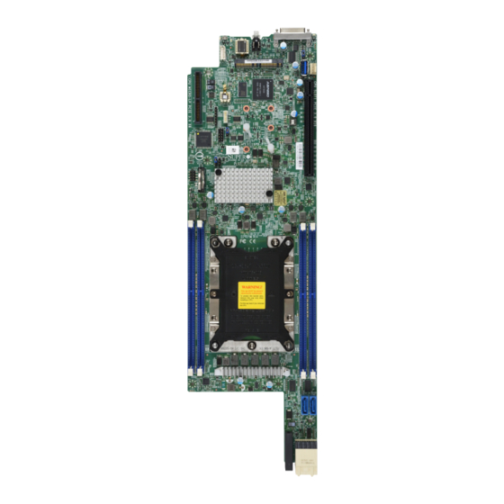
Introduction Congratulations on purchasing your computer motherboard from an industry leader. Supermicro motherboards are designed to provide you with the highest standards in quality and performance. In addition to the motherboard, several important parts that are included with your shipment are listed below. - Page 9 Chapter 1: Introduction Figure 1-1. X11SPD-F Motherboard Image Image of motherboard is not in image database Note: All graphics shown in this manual were based upon the latest PCB revision available at the time of publication of the manual. The motherboard you received may...
- Page 10 Super X11SPD-F User's Manual Figure 1-2. X11SPD-F Motherboard Layout (not drawn to scale) Bottom View Top View JMD2 JMD1 LEDPWR JKVM1 ALERT_LED1 UID_LED1 LEDPWR JKVM1 MH10 USB0/1 MH11 JWD1 JIPMB1 BMC_HB_LED1 BMC_HB_LED1 JMD2:M.2-H PCI-E 3.0 X4 / S-SATA5 JMD2 JUSB3A1 JMD1 JMD1:M.2-H...
-
Page 11: Quick Reference Table
Chapter 1: Introduction Quick Reference Table Jumper Description Default Setting JBT1 CMOS Clear Open (Normal) JPME2 Manufacturing Mode Pins 1-2 (Normal) JWD1 Watch Dog Timer Pins 1-2 (Normal) Connector Description Onboard CMOS battery socket CPU Micro-LP PCI-E 3.0 X 18 Onboard PCH sSATA or SAS Add-On Card IO Selection JPCIE1 CPU Slot1 PCI-E 3.0 X 16... -
Page 12: Motherboard Features
Super X11SPD-F User's Manual Motherboard Features Motherboard Features • Supports an Intel Xeon E-2100 series, 8th Gen Core i3, Pentium, Celeron processors in an LGA3647 socket. Memory • Supports up to 512GB of ECC 3DS LRDIMM with speeds of up to 2933MHz in four slots DIMM Size •... - Page 13 ACPI 6.1, SMBIOS 2.7, PCI F/W 3.0, Plug-and-Play (PnP), RTC wakeup Power Management • Power button override mechanism • Intel Intelligent Power Node Manager (available when the Supermicro Power Manager [SPM] is installed and a special power supply is used) • Management Engine (ME) System Health Monitoring •...
- Page 14 Super X11SPD-F User's Manual Figure 1-3. C621 System Block Diagram PCIe3.0 x 16 PCIe x 16 SLOT DDR 4 DIMMA A Intel 2933/2666/2400/2133MHz PCIe3.0 x 8 DIMMA B (FAR) PCIe x8 MLP SLOT Xeon DDR 4 DIMMA D PCIe3.0 x 4...
-
Page 15: Processor And Chipset Overview
Chapter 1: Introduction 1.2 Processor and Chipset Overview Built upon the functionality and capability of the Intel Xeon E-2100 series, 8th Generation Core i3, Pentium, Celeron processor, and the C621 chipset, this motherboard provides superb system performance, efficient power management, and a set of features based on cutting edge technology to address the needs of next-generation computer users. -
Page 16: Special Features
Super X11SPD-F User's Manual 1.3 Special Features This section describes the health monitoring features of the X11SPD-F motherboard. The motherboard has an onboard ASpeed 2500 Baseboard Management Controller (BMC) that supports system health monitoring. Recovery from AC Power Loss The Basic I/O System (BIOS) provides a setting that determines how the system will respond when AC power is lost and then restored to the system. -
Page 17: System Resource Alert
Chapter 1: Introduction System Resource Alert This feature is available when used with SuperDoctor 5 . SuperDoctor 5 is used to notify the ® user of certain system events. For example, you can configure SuperDoctor 5 to provide you with warnings when the system temperature, CPU temperatures, voltages and fan speeds go beyond a predefined range. -
Page 18: Advanced Power Management
Intelligent Power Node Manager (IPNM) ® Available when the Supermicro Power Manager (SPM) is installed, Intel's Intelligent Power Node Manager (IPNM) provides your system with real-time thermal control and power management for maximum energy efficiency. Although IPNM Specification Version 2.0/3.0 is supported by the BMC (Baseboard Management Controller), your system must also have IPNM-compatible Management Engine (ME) firmware installed to use this feature. -
Page 19: Chapter 2 Installation
Chapter 2: Installation Chapter 2 Installation 2.1 Static-Sensitive Devices Electrostatic Discharge (ESD) can damage electronic com ponents. To avoid damaging your motherboard and your system, it is important to handle it very carefully. The following measures are generally sufficient to protect your equipment from ESD. Precautions •... -
Page 20: Processor And Heatsink Installation
Thermal grease is pre-applied on a new heatsink. No additional thermal grease is needed. • Refer to the Supermicro website for updates on processor support. • All graphics in this manual are for illustrations only. Your components may look different. -
Page 21: Overview Of The Processor Carrier Assembly
Chapter 2: Installation Overview of the Processor Carrier Assembly The processor carrier assembly contains the Intel Xeon Non-Fabric (Non-F) processor and a processor carrier. 1. Non-F Processor 2. Processor Carrier Overview of the CPU Socket The CPU socket is protected by a plastic protective cover. 1. -
Page 22: Overview Of The Processor Heatsink Module
Super X11SPD-F User's Manual Overview of the Processor Heatsink Module The Processor Heatsink Module (PHM) contains a heatsink, a processor carrier, and the Intel Xeon Non-Fabric (Non-F) processor. 1. Heatsink with Thermal Grease 2. Processor Carrier 3. Non-F Processor Processor Heatsink Module... -
Page 23: Creating The Non-F Model Processor Carrier Assembly
Chapter 2: Installation Creating the Non-F Model Processor Carrier Assembly To install a Non-F model processor into the processor carrier, follow the steps below: 1. Hold the processor with the LGA lands (gold contacts) facing up. Locate the small, gold triangle in the corner of the processor and the corresponding hollowed triangle on the processor carrier. -
Page 24: Assembling The Processor Heatsink Module
Super X11SPD-F User's Manual Assembling the Processor Heatsink Module After creating the processor carrier assembly for the Non-F model processor, mount it onto the heatsink to create the processor heatsink module (PHM): 1. Note the label on top of the heatsink, which marks the heatsink mounting holes as 1, 2, 3, and 4. -
Page 25: Preparing The Cpu Socket For Installation
Chapter 2: Installation Preparing the CPU Socket for Installation This motherboard comes with a plastic protective cover installed on the CPU socket. Remove it from the socket to install the Processor Heatsink Module (PHM). Gently pull up one corner of the plastic protective cover to remove it. CPU Socket with Plastic Protective Cover Remove the plastic protective cover from the CPU socket. -
Page 26: Installing The Processor Heatsink Module
Super X11SPD-F User's Manual Installing the Processor Heatsink Module After assembling the Processor Heatsink Module (PHM), install the PHM onto the CPU socket: 1. Align hole 1 of the heatsink with the printed triangle on the CPU socket. See the left image below. -
Page 27: Removing The Processor Heatsink Module
Chapter 2: Installation Removing the Processor Heatsink Module Before removing the processor heatsink module (PHM) from the motherboard, unplug the AC power cord from all power supplies after shutting down the system. Then follow the steps below: 1. Use a T30 Torx-bit screwdriver to loosen the four screws in a backwards sequence of #4, #3, #2, and #1. -
Page 28: Motherboard Installation
Super X11SPD-F User's Manual 2.2 Motherboard Installation All motherboards have standard mounting holes to fit different types of chassis. Make sure that the locations of all the mounting holes for both the motherboard and the chassis match. Although a chassis may have both plastic and metal mounting fasteners, metal ones are highly recommended because they ground the motherboard to the chassis. -
Page 29: Installing The Motherboard
Chapter 2: Installation Installing the Motherboard 1. Install the I/O shield into the back of the chassis, if applicable. 2. Locate the mounting holes on the motherboard. See the previous page for the location. 3. Locate the matching mounting holes on the chassis. Align the mounting holes on the motherboard against the mounting holes on the chassis. -
Page 30: Installing The Motherboard Into The Microblade Chassis
Super X11SPD-F User's Manual Installing the Motherboard into the Microblade Chassis 1. When the motherboard is securely installed on the mounting tray, push the tray into the Microblade chassis as shown below. 2. Once the mounting tray is pushed into the chassis, the connectors on the motherboard's edge will make contact with the chassis backplane, which provides the connections to the chassis power, network, and other I/O devices. -
Page 31: Memory Support And Installation
Chapter 2: Installation 2.4 Memory Support and Installation Note: Check the Supermicro website for recommended memory modules. Important: Exercise extreme care when installing or removing DIMM modules to pre- vent any possible damage. Memory Support The motherboard supports up to 512GB of ECC 3DS LRDIMM with speeds of up to 2933MHz in four slots. -
Page 32: Dimm Installation
Super X11SPD-F User's Manual DIMM Installation LEDPWR JKVM1 MH10 USB0/1 MH11 1. Insert the desired number of DIMMs into BMC_HB_LED1 JMD2:M.2-H PCI-E 3.0 X4 / S-SATA5 JMD2 JMD1 the memory slots based on Recommended JMD1:M.2-H PCI-E 3.0 X4 / S-SATA1... -
Page 33: Connectors
JMD2:M.2-H PCI-E 3.0 X4 1. Power Connector / S-SATA5 JMD2 JMD1 JMD1:M.2-H PCI-E 3.0 X4 / S-SATA1 JWD1:WATCH DOG 1-2:RST 2-3:NMI 2. Power Button X11SPD-F REV: 1.0 DESIGNED IN USA SRW6 SRW3 SRW3 SRW3 JRK1 SRW8 SRW7 SRW7 SRW7 J25 : SATA/SAS SELECT... - Page 34 Super X11SPD-F User's Manual Fan Header The X11SPD-F has one 4-pin fan header (FAN1). This header is backwards compatible with the traditional 3-pin fans. However, fan speed control is available for 4-pin fans only by the Thermal Management via the IPMI 2.0 interface. Refer to the table below for pin definitions.
- Page 35 BMC_HB_LED1 1. BMC External Header JMD2:M.2-H PCI-E 3.0 X4 / S-SATA5 JMD2 JMD1 JMD1:M.2-H PCI-E 3.0 X4 / S-SATA1 JWD1:WATCH DOG 1-2:RST 2-3:NMI X11SPD-F REV: 1.0 DESIGNED IN USA SRW6 SRW3 SRW3 SRW3 JRK1 SRW8 SRW7 SRW7 SRW7 J25 : SATA/SAS SELECT...
- Page 36 Super X11SPD-F User's Manual TPM Header The JTPM1 header is used to connect a Trusted Platform Module (TPM)/Port 80, which is available from a third-party vendor. A TPM/Port 80 connector is a security device that supports encryption and authentication in hard drives. It allows the motherboard to deny access if the TPM associated with the hard drive is not installed in the system.
- Page 37 The Complex Programmable Logic Device, or CLPD, Header (JCPLD1) allows the backplane to support NVMe devices. SAS Ports The X11SPD-F motherboard has two Serial Attached SCSI 3.0 ports (SAS0 and SAS1). Refer to the tables below for pin definitions No pin definitions available (checked X11SDD manual, but chart is missing).
- Page 38 Super X11SPD-F User's Manual Universal Serial Bus (USB) Header There is one USB 3.0 Gen 1 header (JUSB3A1) on the motherboard to provide front access USB connection with a cable (not included). CONFIRM USB 3.0 Gen 1Header Pin Definitions Pin#...
- Page 39 USB0/1 MH11 BMC_HB_LED1 JMD2:M.2-H PCI-E 3.0 X4 / S-SATA5 JMD2 JMD1 JMD1:M.2-H PCI-E 3.0 X4 / S-SATA1 JWD1:WATCH DOG 1-2:RST 2-3:NMI X11SPD-F REV: 1.0 DESIGNED IN USA SRW6 SRW3 SRW3 SRW3 JRK1 SRW8 SRW7 SRW7 SRW7 J25 : SATA/SAS SELECT...
- Page 40 Super X11SPD-F User's Manual Unit Identifier Switch/UID LED Indicator A Unit Identifier (UID) switch and an LED indicator are located on the motherboard. The UID switch is located at UID, on the back panel. The UID LED (UID_LED1) is located next to the UID switch.
- Page 41 USB0/1 MH11 BMC_HB_LED1 JMD2:M.2-H PCI-E 3.0 X4 / S-SATA5 JMD2 JMD1 JMD1:M.2-H PCI-E 3.0 X4 / S-SATA1 JWD1:WATCH DOG 1-2:RST 2-3:NMI X11SPD-F REV: 1.0 DESIGNED IN USA SRW6 SRW3 SRW3 SRW3 JRK1 SRW8 SRW7 SRW7 SRW7 J25 : SATA/SAS SELECT...
- Page 42 Super X11SPD-F User's Manual RAID Key Header A RAID Key header is located at JRK1 on the motherboard. The RAID key is used to support NVMe SDD. Intel RAID KEY Pin Definitions Pin# Definition LEDPWR JKVM1 Ground MH10 USB0/1 MH11 BMC_HB_LED1 3.3V Standby...
-
Page 43: Jumper Settings
Chapter 2: Installation 2.6 Jumper Settings How Jumpers Work To modify the operation of the motherboard, jumpers can be used to choose between optional settings. Jumpers create shorts between two pins to change the function of the connector. Pin 1 is identified with a square solder pad on the printed circuit board. See the diagram at right for an example of jumping pins 1 and 2. - Page 44 Super X11SPD-F User's Manual CMOS Clear BT1 is used to clear CMOS, which will also clear any passwords. Instead of pins, this jumper consists of contact pads to prevent accidentally clearing the contents of CMOS. To Clear CMOS 1. First power down the system and unplug the power cord(s).
- Page 45 USB0/1 MH11 BMC_HB_LED1 JMD2:M.2-H PCI-E 3.0 X4 / S-SATA5 JMD2 JMD1 JMD1:M.2-H PCI-E 3.0 X4 / S-SATA1 JWD1:WATCH DOG 1-2:RST 2-3:NMI X11SPD-F REV: 1.0 DESIGNED IN USA SRW6 SRW3 SRW3 SRW3 JRK1 SRW8 SRW7 SRW7 SRW7 J25 : SATA/SAS SELECT...
- Page 46 Super X11SPD-F User's Manual Watch Dog JWD1 controls the Watch Dog function. Watch Dog is a monitor that can reboot the system when a software application hangs. Jumping pins 1-2 will cause Watch Dog to reset the system if an application hangs. Jumping pins 2-3 will generate a non-maskable interrupt signal for the application that hangs.
-
Page 47: Led Indicators
USB0/1 MH11 BMC_HB_LED1 JMD2:M.2-H PCI-E 3.0 X4 / S-SATA5 JMD2 JMD1 JMD1:M.2-H PCI-E 3.0 X4 / S-SATA1 JWD1:WATCH DOG 1-2:RST 2-3:NMI X11SPD-F REV: 1.0 DESIGNED IN USA SRW6 SRW3 SRW3 SRW3 JRK1 SRW8 SRW7 SRW7 SRW7 J25 : SATA/SAS SELECT... - Page 48 Super X11SPD-F User's Manual Unit Identifier Switch/UID LED Indicator A Unit Identifier (UID) switch and an LED indicator are located on the motherboard. The UID switch is located at UID, on the back panel. The UID LED (UID_LED1) is located next to the UID switch.
- Page 49 BMC_HB_LED1 JMD2:M.2-H PCI-E 3.0 X4 / S-SATA5 JMD2 JMD1 JMD1:M.2-H PCI-E 3.0 X4 / S-SATA1 1. Onboard Power LED JWD1:WATCH DOG 1-2:RST 2-3:NMI X11SPD-F REV: 1.0 DESIGNED IN USA SRW6 SRW3 SRW3 SRW3 JRK1 SRW8 SRW7 SRW7 SRW7 J25 : SATA/SAS SELECT...
- Page 50 Super X11SPD-F User's Manual System Failure LED ALERT_LED1 is the System Failure LED. When this LED is solid red, it means a system overheat. When this LED is blinking red, it means a power failure or fan failure has occurred.
-
Page 51: Chapter 3 Troubleshooting
Chapter 3: Troubleshooting Chapter 3 Troubleshooting 3.1 Troubleshooting Procedures Use the following procedures to troubleshoot your system. If you have followed all of the procedures below and still need assistance, refer to the ‘Technical Support Procedures’ and/ or ‘Returning Merchandise for Service’ section(s) in this chapter. Always disconnect the AC power cord before adding, changing or installing any non hot-swap hardware components. -
Page 52: No Video
Super X11SPD-F User's Manual No Video 1. If the power is on but you have no video, remove all the add-on cards and cables. 2. Use the speaker to determine if any beep codes exist. Refer to Appendix A for details on beep codes. -
Page 53: Losing The System's Setup Configuration
Chapter 3: Troubleshooting Losing the System's Setup Configuration 1. Make sure that you are using a high quality power supply. A poor quality power supply may cause the system to lose the CMOS setup information. Refer to Section 1.6 for details on recommended power supplies. - Page 54 Super X11SPD-F User's Manual 3. Using the minimum configuration for troubleshooting: Remove all unnecessary components (starting with add-on cards first), and use the minimum configuration (but with a CPU and a memory module installed) to identify the trouble areas. Refer to the steps listed in Section A above for proper troubleshooting procedures.
-
Page 55: Technical Support Procedures
Chapter 3: Troubleshooting 3.2 Technical Support Procedures Before contacting Technical Support, please take the following steps. Also, note that as a motherboard manufacturer, we do not sell directly to end-users, so it is best to first check with your distributor or reseller for troubleshooting services. They should know of any possible problem(s) with the specific system configuration that was sold to you. -
Page 56: Frequently Asked Questions
3.3 Frequently Asked Questions Question: What type of memory does my motherboard support? Answer: The X11SPD-F motherboard supports up to 512GB ECC 3DS LRDIMM with speeds of up to 2933MHz in four slots. See Section 2.4 for details on installing memory. -
Page 57: Battery Removal And Installation
Chapter 3: Troubleshooting 3.4 Battery Removal and Installation Battery Removal To remove the onboard battery, follow the steps below: 1. Power off your system and unplug your power cable. 2. Using a tool such as a pen or a small screwdriver, push the battery lock outwards to unlock it. -
Page 58: Returning Merchandise For Service
Super X11SPD-F User's Manual 3.5 Returning Merchandise for Service A receipt or copy of your invoice marked with the date of purchase is required before any warranty service will be rendered. You can obtain service by calling your vendor for a Returned Merchandise Authorization (RMA) number. -
Page 59: Introduction
Chapter 4: BIOS Chapter 4 UEFI BIOS 4.1 Introduction This chapter describes the AMIBIOS™ Setup utility for the X11SPD motherboard. The BIOS is stored on a chip and can be easily upgraded using a flash program. Note: Due to periodic changes to the BIOS, some settings may have been added or deleted and might not yet be recorded in this manual. -
Page 60: Main Setup
Super X11SPD-F User's Manual 4.2 Main Setup When you first enter the AMI BIOS setup utility, you will enter the Main setup screen. You can always return to the Main setup screen by selecting the Main tab on the top of the screen. - Page 61 Chapter 4: BIOS Memory Information Total Memory This feature displays the total size of memory available in the system.
-
Page 62: Advanced
Super X11SPD-F User's Manual 4.3 Advanced Use this menu to configure advanced settings. Warning: Take caution when changing the Advanced settings. An incorrect value, a very high DRAM frequency or an incorrect BIOS timing setting may cause the system to malfunction. - Page 63 Chapter 4: BIOS Wait For "F1" If Error This feature forces the system to wait until the F1 key is pressed if an error occurs. The options are Disabled and Enabled. Interrupt 19 Capture Interrupt 19 is the software interrupt that handles the boot disk function. When this feature is set to Immediate, the ROM BIOS of the host adaptors will "capture"...
- Page 64 Super X11SPD-F User's Manual CPU Configuration The following CPU information will display: • Processor BSP Revision • Processor Socket • Processor ID • Processor Frequency • Processor Max Ratio • Processor Min Ratio • Microcode Revision • L1 Cache RAM •...
- Page 65 Chapter 4: BIOS Intel Virtualization Technology Use this feature to enable the Vanderpool Technology. This technology allows the system to run several operating systems simultaneously. The options are Disable and Enable. PPIN Control Select Unlock/Enable to use the Protected-Processor Inventory Number (PPIN) in the system. The options are Unlock/Disable and Unlock/Enable.
- Page 66 Super X11SPD-F User's Manual Advanced Power Management Configuration Power Technology Select Energy Efficient to support power-saving mode. Select Custom to customize system power settings. Select Disabled to disable power-saving settings. The options are Disable, Energy Efficient, and Custom. Power Performance Tuning When enabled, this item selects whether the BIOS or Operating System can change the energy performance bias tuning.
- Page 67 Chapter 4: BIOS Turbo Mode This feature will enable dynamic control of the processor, allowing it to run above stock frequency. The options are Disable and Enable. Hardware PM State Control Hardware P-States This setting allows the user to select between OS and hardware-controlled P-states. Selecting Native Mode allows the OS to choose a P-state.
- Page 68 Super X11SPD-F User's Manual CPU T State Control Software Controlled T-States Use this feature to enable Software Controlled T-States. The options are Enable and Disable. Chipset Configuration Warning: Setting the wrong values in the sections below may cause the system to malfunction.
- Page 69 Chapter 4: BIOS Link L1 Enable Select Enable for the QPI to enter the L1 state for power saving. The options are Dis- able, Enable, and Auto. IO Directory Cache (IODC) IO Directory Cache is an 8-entry cache that stores the directory state of remote IIO writes and memory lookups, and saves directory updates.
- Page 70 Super X11SPD-F User's Manual LLC Dead Line Alloc Select Enable to optimally fill dead lines in LLC. Select Disable to never fill dead lines in LLC. The options are Disable, Enable, and Auto. Isoc Mode Isochronous (Isoc) mode allows time-sensitive processes to be given priority. The options are Disable, Enable, and Auto.
- Page 71 Chapter 4: BIOS IMC Interleaving This feature allows the user to configure Integrated Memory Controller (IMC) Interleaving settings. The options are Auto, 1-way Interleave, and 2-way Interleave. Memory Topology This item displays the information of onboard memory modules as detected by the BIOS.
- Page 72 Super X11SPD-F User's Manual Patrol Scrub Patrol Scrub is a process that allows the CPU to correct correctable memory errors detected on a memory module and send the correction to the requestor (the original source). When this item is set to Enable, the IO hub will read and write back one cache line every 16K cycles if there is no delay caused by internal processing.
- Page 73 Chapter 4: BIOS PCI-E Port Max Payload Size Selecting Auto for this feature will enable the motherboard to automatically detect the maximum Transaction Layer Packet (TLP) size for the connected PCI-E device, allowing for maximum I/O efficiency. Selecting 128B or 256B will designate maximum packet size of 128 or 256.
- Page 74 Super X11SPD-F User's Manual PassThrough DMA Use this feature to allow devices such as network cards to access the system memory without using a processor. Select Enable to use the Non-Isoch VT_D Engine Pass Through Direct Memory Access (DMA) support. The options are Enable and Disable.
- Page 75 Chapter 4: BIOS Hot Plug Capable (Available when the device is detected by the system) Use this feature to enable hot plug support for PCIe root ports 1A~1D. The options are Disable and Enable. VMD Config for PStack1 Intel® VMD for Volume Management Device for PStack1 Select Enable to use the Intel Volume Management Device Technology for this stack.
- Page 76 Super X11SPD-F User's Manual South Bridge The following USB information will display: • USB Module Version • USB Devices Legacy USB Support This feature enables support for USB 2.0 and older. The options are Enabled, Disabled, and Auto. XHCI Hand-off When this feature is disabled, the motherboard will not support USB 3.0.
- Page 77 Chapter 4: BIOS SATA Configuration When this submenu is selected, the AMI BIOS automatically detects the presence of the SATA devices that are supported by the Intel PCH chipset and displays the following items: SATA Controller Use this feature to enable or disable the onboard SATA controller supported by the Intel PCH chipset.
- Page 78 Super X11SPD-F User's Manual Spin Up Device On an edge detect from 0 to 1, set this item to allow the PCH to initialize the device. The options are Disable and Enable. SATA Device Type Use this feature to specify if the SATA port specified by the user should be connected to a Solid State drive or a Hard Disk Drive.
- Page 79 Chapter 4: BIOS sSATA Port 0 ~ 3 This item displays the information detected on the installed SATA drive on the particular SATA port. Hot Plug Set this feature to Enable for hot plug support, which will allow the user to replace a SATA drive without shutting down the system.
- Page 80 Super X11SPD-F User's Manual Maximum Read Request Use this feature to select the Maximum Read Request size of the PCI-Express device, or select Auto to allow the system BIOS to determine the value. The options are Auto, 128 Bytes, 256 Bytes, 512 Bytes, 1024 Bytes, 2048 Bytes, and 4096 Bytes.
- Page 81 Chapter 4: BIOS Bus Master Enable This feature enables a device connected to the bus to intiate Direct Memory Access (DMA) transactions. When DIsabled is selected, the PCI Bus Driver disables Bus Master Attribute for Pre-Boot DMA Protection. When Enabled is selected, the PCI Bus Driver enables BUs Master Atribute for DMA transactions.
- Page 82 Super X11SPD-F User's Manual Ipv6 HTTP Support Select Enabled to enable IPv6 HTTP boot support. The options are Disabled and Enabled. PXE boot wait time Use this feature to specify the wait time to press the ESC key to abort the PXE boot. Press "+"...
- Page 83 Chapter 4: BIOS Change Settings This feature specifies the base I/O port address and the Interrupt Request address of a serial port specified by the user. Select Auto to allow the BIOS to automatically assign the base I/O and IRQ address. The options are Auto, (IO=2F8h; IRQ=3), (IO=3F8h; IRQ=3), (IO=3E8h;...
- Page 84 Super X11SPD-F User's Manual Data Bits Use this feature to set the data transmission size for Console Redirection. The options are 7 and 8. Parity A parity bit can be sent along with regular data bits to detect data transmission errors. Select Even if the parity bit is set to 0, and the number of 1's in data bits is even.
- Page 85 Chapter 4: BIOS Putty KeyPad This feature selects Function Keys and KeyPad settings for Putty, which is a terminal emulator designed for the Windows OS. The options are VT100, LINUX, XTERMR6, SCO, ESCN, and VT400. Redirection After BIOS POST Use this feature to enable or disable legacy console redirection after BIOS POST. When set to Bootloader, legacy console redirection is disabled before booting the OS.
- Page 86 Super X11SPD-F User's Manual Parity A parity bit can be sent along with regular data bits to detect data transmission errors. Select Even if the parity bit is set to 0, and the number of 1's in data bits is even. Select Odd if the parity bit is set to 0, and the number of 1's in data bits is odd.
- Page 87 Chapter 4: BIOS set to Always Enable, legacy Console Redirection remains enabled when booting the OS. The options are Always Enable and Bootloader. Legacy Console Redirection Legacy Redirection COM Port Use this feature to select a COM port to display redirection of Legacy OS and Legacy OPROM messages.
- Page 88 Super X11SPD-F User's Manual Terminal Type Use this feature to select the target terminal emulation type for Console Redirection. Select VT100 to use the ASCII character set. Select VT100+ to add color and function key support. Select ANSI to use the extended ASCII character set. Select VT-UTF8 to use UTF8 encoding to map Unicode characters into one or more bytes.
- Page 89 Chapter 4: BIOS Trusted Computing *This motherboard supports TPM 1.2 and 2.0. The following Trusted Platform Module (TPM) information will display if a TPM 2.0 module is detected: • Vendor • Firmware Version Security Device Support If this feature and the TPM jumper on the motherboard are both set to Enabled, onboard security devices will be enabled for TPM support to enhance data integrity and network security.
- Page 90 Use this feature to disable or enable Platform Hiearchy (PH) Randomization. The options are Disabled and Enabled. SMCI BIOS-Based TPM Provision Support Use this feature to enable the Supermicro TPM Provision support. The options are Disabled and Enabled. TXT Support Intel Trusted Execution Technology (TXT) helps protect against software-based attacks and ensures protection, confidentiality, and integrity of data stored or created on the system.
- Page 91 Chapter 4: BIOS Discard Changes and Exit Use this feature to discard all changes and exit TLS settings. Delete Certification Use this feature to delete certification. iSCSI Configuration iSCSI Initiator Name This feature allows the user to enter the unique name of the iSCSI Initiator in IQN format. Once the name of the iSCSI Initiator is entered into the system, configure the proper settings for the following items.
-
Page 92: Event Logs
Super X11SPD-F User's Manual 4.3 Event Logs Use this menu to configure event log settings. Change SMBIOS Event Log Settings Enabling/Disabling Options SMBIOS Event Log Change this feature to enable or disable all features of the SMBIOS Event Logging during system boot. - Page 93 Chapter 4: BIOS Smbios Event Log Standard Settings Log System Boot Event Select Enabled to log system boot events. The options are Enabled and Disabled. MECI (Multiple Event Count Increment) Enter the increment value for the multiple event counter. Enter a number between 1 to 255. The default setting is 1.
-
Page 94: Ipmi
Super X11SPD-F User's Manual 4.4 IPMI Use this menu to configure Intelligent Platform Management Interface (IPMI) settings. BMC Firmware Revision This feature indicates the BMC firmware revision in your system. Status of BMC This feature indicates the status of the BMC firmware installed in your system. - Page 95 Chapter 4: BIOS keep all system event logs after each system reboot. The options are No, Yes, On next reset, and Yes, On every reset. When SEL is Full This feature allows the user to decide what the BIOS should do when the system event log is full.
- Page 96 Super X11SPD-F User's Manual Subnet Mask This item displays the sub-network that this computer belongs to. The value of each three- digit number separated by dots should not exceed 255. Station MAC Address This item displays the Station MAC address for this computer. Mac addresses are 6 two-digit hexadecimal numbers.
-
Page 97: Security
Chapter 4: BIOS 4.5 Security Use this menu to configure the security settings for the system. Administrator Password Use this feature to set the administrator password which is required to enter the BIOS setup utility. The length of the password should be from 3 to 20 characters long. User Password Use this feature to set a user password. - Page 98 Super X11SPD-F User's Manual Secure Boot Mode This feature allows the user to select the desired secure boot mode for the system. The options are Standard and Custom. *If Secure Boot Mode is set to Customized, Key Management features are available...
- Page 99 Chapter 4: BIOS Secure Boot variable Platform Key (PK) Update Select Yes to load the new Platform Keys (PK) from the manufacturer's defaults. Select No to load the Platform Keys from a file. The options are Yes and No. ...
- Page 100 Super X11SPD-F User's Manual OsRecovery Signatures Update Select Yes to load a factory default dbr or No to load from a file on an external media. Append Select Yes to add the dbr from the manufacturer's defaults list to the existing dbr. Select...
-
Page 101: Boot
Chapter 4: BIOS 4.7 Boot Use this menu to configure boot settings. Boot Mode Select Use this feature to select the type of device that the system is going to boot from. The options are Legacy, UEFI, and Dual. Legacy to EFI Support This feature enables the system to boot to EFI OS if boot fails from Legacy boot order. - Page 102 Super X11SPD-F User's Manual • Boot Order #7 • Boot Order #8 • Boot Order #9 • Boot Order #10 • Boot Order #11 • Boot Order #12 • Boot Order #13 • Boot Order #14 • Boot Order #15 •...
-
Page 103: Save & Exit
Chapter 4: BIOS 4.8 Save & Exit Use this menu to configure save and exit settings. Save Options Discard Changes and Exit Select this feature to quit the BIOS Setup without making any permanent changes to the system configuration and reboot the computer. Select Discard Changes and Exit from the Exit menu and press <Enter>. - Page 104 Super X11SPD-F User's Manual Default Options Restore Defaults To set this feature, select Restore Optimized Defaults and press <Enter>. These are factory settings designed for maximum system performance but not for maximum stability. Save as User Defaults To set this feature, select Save as User Defaults from the Exit menu and press <Enter>. This enables the user to save any changes to the BIOS setup for future use.
-
Page 105: Appendix A Software Installation
The Supermicro website contains drivers and utilities for your system at https://www. supermicro.com/wftp/driver. Some of these must be installed, such as the chipset driver. After accessing the website, go into the CDR_Images (in the parent directory of the above link) and locate the ISO file for your motherboard. Download this file to create a DVD of the drivers and utilities it contains. -
Page 106: Superdoctor 5
SATA settings back to your original settings. A.2 SuperDoctor ® The Supermicro SuperDoctor 5 is a hardware monitoring program that functions in a command-line or web-based interface in Windows and Linux operating systems. The program monitors system health information such as CPU temperature, system voltages, system power consumption, fan speed, and provides alerts via email or Simple Network Management Protocol (SNMP). -
Page 107: Appendix B Software Installation
The Supermicro website contains drivers and utilities for your system at https://www. supermicro.com/wftp/driver. Some of these must be installed, such as the chipset driver. After accessing the website, go into the CDR_Images (in the parent directory of the above link) and locate the ISO file for your motherboard. Download this file to create a DVD of the drivers and utilities it contains. -
Page 108: Superdoctor 5
SATA settings back to your original settings. B.2 SuperDoctor ® The Supermicro SuperDoctor 5 is a hardware monitoring program that functions in a command-line or web-based interface in Windows and Linux operating systems. The program monitors system health information such as CPU temperature, system voltages, system power consumption, fan speed, and provides alerts via email or Simple Network Management Protocol (SNMP). -
Page 109: Appendix C Standardized Warning Statements
The following statements are industry standard warnings, provided to warn the user of situations which have the potential for bodily injury. Should you have questions or experience difficulty, contact Supermicro's Technical Support department for assistance. Only certified technicians should attempt to install or configure components. - Page 110 Super X11SPD-F User's Manual Attention Danger d'explosion si la pile n'est pas remplacée correctement. Ne la remplacer que par une pile de type semblable ou équivalent, recommandée par le fabricant. Jeter les piles usagées conformément aux instructions du fabricant. ¡Advertencia! Existe peligro de explosión si la batería se reemplaza de manera incorrecta.
- Page 111 Appendix C: Standardized Warning Statements Product Disposal Warning! Ultimate disposal of this product should be handled according to all national laws and regulations. 製品の廃棄 この製品を廃棄処分する場合、 国の関係する全ての法律 ・ 条例に従い処理する必要があります。 警告 本产品的废弃处理应根据所有国家的法律和规章进行。 警告 本產品的廢棄處理應根據所有國家的法律和規章進行。 Warnung Die Entsorgung dieses Produkts sollte gemäß allen Bestimmungen und Gesetzen des Landes erfolgen.
-
Page 112: Appendix D Uefi Bios Recovery
Warning: Do not upgrade the BIOS unless your system has a BIOS-related issue. Flashing the wrong BIOS can cause irreparable damage to the system. In no event shall Supermicro be liable for direct, indirect, special, incidental, or consequential damages arising from a BIOS update. -
Page 113: Recovering The Main Bios Block With A Usb Device
USB device or a writable CD/DVD. Note 1: If you cannot locate the "Super.ROM" file in your drive disk, visit our website www.supermicro.com to download the BIOS package. Extract the BIOS binary im- age into a USB flash device and rename it "Super.ROM" for the BIOS recovery use. - Page 114 Super X11SPD-F User's Manual 3. After locating the healthy BIOS binary image, the system will enter the BIOS Recovery menu as shown below. Note: At this point, you may decide if you want to start the BIOS recovery. If you decide to proceed with BIOS recovery, follow the procedures below.
- Page 115 Appendix D: UEFI BIOS Recovery 5. After the BIOS recovery process is complete, press any key to reboot the system. 6. Using a different system, extract the BIOS package into a USB flash drive. 7. Press <Del> continuously during system boot to enter the BIOS Setup utility. From the top of the tool bar, select Boot to enter the submenu.
- Page 116 Super X11SPD-F User's Manual 8. When the UEFI Shell prompt appears, type fs# to change the device directory path. Go to the directory that contains the BIOS package you extracted earlier from Step 6. Enter flash.nsh BIOSname.### at the prompt to start the BIOS update process.
Need help?
Do you have a question about the X11SPD-F and is the answer not in the manual?
Questions and answers