Table of Contents
Advertisement
Quick Links
Advertisement
Table of Contents

Related Manuals for Supermicro X11SSQ-L


Summary of Contents for Supermicro X11SSQ-L
- Page 1 X11SSQ X11SSQ-L USER’S MANUAL Revision 1.0b...
- Page 2 State of California, USA. The State of California, County of Santa Clara shall be the exclusive venue for the resolution of any such disputes. Supermicro's total liability for all claims will not exceed the price paid for the hardware product.
- Page 3 PCI Express 2.0/3.0 interface, DDR4, SATA3.0, HDMI, DisplayPort, Quick Synch Video, and a combination of USB 2.0 and 3.0 ports. While the X11SSQ-L utilizes the Intel H110 chipset, the X11SSQ utilizes the Intel Q170 chipset and offers the following additional features: RAID, AMT/vPRO M.2, and GPIO.
- Page 4 Super Micro Computer, Inc. 980 Rock Ave. San Jose, CA 95131 U.S.A. Tel: +1 (408) 503-8000 Fax: +1 (408) 503-8008 Email: marketing@supermicro.com (General Information) support@supermicro.com (Technical Support) Website: www.supermicro.com Europe Address: Super Micro Computer B.V. Het Sterrenbeeld 28, 5215 ML...
-
Page 5: Table Of Contents
Preface Table of Contents Chapter 1 Introduction 1.1 Checklist ..........................8 Quick Reference .......................12 Quick Reference Table ......................13 Motherboard Features .......................15 1.2 Processor and Chipset Overview ..................20 1.3 Special Features ........................20 Recovery from AC Power Loss ..................20 1.4 System Health Monitoring ....................21 Onboard Voltage Monitors ....................21 Fan Status Monitor with Firmware Control ...............21 Environmental Temperature Control .................21... - Page 6 Super X11SSQ/-L User's Manual 2.4 Motherboard Installation .....................33 Tools Needed ........................33 Location of Mounting Holes ....................33 Installing the Motherboard....................34 2.5 Rear I/O Ports ........................35 2.6 Front Control Panel ......................41 2.7 Connectors .........................44 Power Connections ......................44 Headers ..........................46 2.8 Jumper Settings .........................53 How Jumpers Work ......................53 2.9 LED Indicators ........................58 Chapter 3 Troubleshooting...
- Page 7 Preface 4-4 Security ..........................101 4-5 Boot ..........................104 4-6 Save & Exit ........................106 Chapter 5 X11SSQ-L BIOS 5.1 Introduction ........................108 Starting the Setup Utility ....................108 5.2 Main Setup ........................109 5-3 Advanced Setup Configurations ..................111 5-4 Security ..........................133 5-5 Boot ..........................136 5-6 Save &...
-
Page 8: Checklist
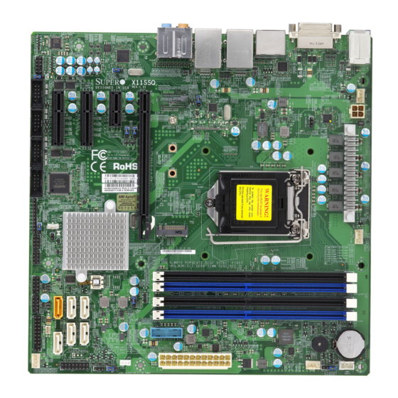
• Product safety info: http://www.supermicro.com/about/policies/safety_information.cfm • If you have any questions, please contact our support team at: support@supermicro.com This manual may be periodically updated without notice. Please check the Supermicro website for possible updates to the manual revision level. - Page 9 Chapter 1: Introduction Figure 1-1. X11SSQ Motherboard Image Note: All graphics shown in this manual were based upon the latest PCB revision available at the time of publication of the manual. The motherboard you received may or may not look exactly the same as the graphics shown in this manual.
- Page 10 Super X11SSQ/-L User's Manual Figure 1-2. X11SSQ-L Motherboard Image Note: All graphics shown in this manual were based upon the latest PCB revision available at the time of publication of the manual. The motherboard you received may or may not look exactly the same as the graphics shown in this manual.
- Page 11 (2.0), J23 (M.2), DIMMA2, DIMMB2, SLOT5 PCI-E 3.0 X4, I-SATA4, I-SATA5, COM3, COM4, JP7 (GPIO), I-SGPIO1, and I-SGPIO2. Note 3: Slot4 and Slot6 are PCI-E 3.0 on X11SSQ and PCI-E 2.0 on X11SSQ-L Note 4: Components not documented are for internal testing only.
-
Page 12: Quick Reference
See Chapter 2 for detailed information on jumpers, I/O ports, and JF1 front panel connec- tions. Jumpers/LED indicators not indicated are used for testing only. • Not all listed features are available on the X11SSQ-L model. Please refer to Page 11 for more information. •... -
Page 13: Quick Reference Table
Trusted Platform Module/Port 80 Connector KB/Mouse Keyboard/Mouse Connector (Back Panel) LAN1/LAN2 LAN (RJ45) Ports (LAN2 on X11SSQ only) SLOT4 PCH PCI-E 3.0 x4 Slot on X11SSQ (PCI-E 2.0 x4 Slot on X11SSQ-L) Note: Table is continued on the next page. - Page 14 Connector Description SLOT5 PCH PCI-E 3.0 x4 Slot (X11SSQ only) SLOT6 PCH PCI-E 3.0 x1 Slot on X11SSQ (PCI-E 2.0 x1 Slot on X11SSQ-L) SLOT7 CPU PCI-E 3.0 x16 Slot Internal Speaker/Buzzer USB0/1, 2/3, 8/9 Back panel Universal Serial Bus (USB) Ports (Ports 8/9: USB 3.0) (USB2/3 on X11SSQ only) USB4/5, 6/7, 10/11 Front Accessible USB Headers (Headers 10/11: USB 3.0)
-
Page 15: Motherboard Features
One (1) CPU PCI-Express 3.0 x16 slot • One (1) PCH PCI-Express 3.0 x1 slot for X11SSQ, One (1) PCH PCI-Express 2.0 x1 slot for X11SSQ-L • Two (2) PCH PCI-Express 3.0 x4 slots for X11SSQ, One (1) PCH PCI-Express 2.0 x4 slot for X11SSQ-L Network •... - Page 16 Super X11SSQ/-L User's Manual Motherboard Features Peripheral Devices • Four (4) USB 2.0 ports on the rear I/O panel (USB0/1 and USB2/3) (USB2/3 not available on X11SSQ-L) • Two (2) USB 3.0 port on the rear I/O panel (USB8/9) •...
- Page 17 Chapter 1: Introduction Motherboard Features LED Indicators • CPU/System overheating • Power/Suspend state indicator • Fan Failure • HDD activity • LAN activity Dimensions • uATX, 9.6" x 9.6", (24.4cm x 24.4 cm) Note 1: The CPU maximum thermal design power (TDP) is subject to chassis and heatsink cooling restrictions.
- Page 18 Super X11SSQ/-L User's Manual Figure 1-4. X11SSQ System Block Diagram PCIe3.0_x16 SVID IMVP8 PCIe x16 SLOT #7 MPS VRM 8.0GT/s INTEL LGA1151 Digital port 3 DisplayPort DDR4 (CHA) DIMMA1 (Black) Digital port 2 HDMI (Socket-H4) DIMMA2 (Blue) 2133/1866MT/s Digital port 1 DVI-D DDR4 (CHB) DIMMB1...
- Page 19 Chapter 1: Introduction Figure 1-5. X11SSQ-L System Block Diagram PCIe3.0_x16 SVID IMVP8 PCIe x16 SLOT #7 MPS VRM 8.0GT/s INTEL LGA1151 Digital port 3 DisplayPort DDR4 (CHA) Digital port 2 DIMMA1 (Blue) HDMI (Socket-H4) 2133/1866MT/s Digital port 1 DVI-D DDR4 (CHB)
-
Page 20: Processor And Chipset Overview
Intel Turbo Boost Technology • Intel Rapid Storage Technology • DDR4 Memory Support up to 2133MHz 64GB (up to 32GB on X11SSQ-L) • Three independent Graphics Displays (two on X11SSQ-L) with Audio Stream, VP8, VP9, HEVC, OpenGL 4.3/4.4, Intel Quick Sync Video Technology 1.3 Special Features... -
Page 21: System Health Monitoring
Chapter 1: Introduction 1.4 System Health Monitoring This section describes the PC health monitoring features of the board. All have an onboard System Hardware Monitoring chip that supports PC health monitoring. Onboard Voltage Monitors The onboard voltage monitor will continuously scan crucial voltage levels. Once a voltage becomes unstable, it will give a warning or send an error message to the screen. -
Page 22: Acpi Features
Super X11SSQ/-L User's Manual 1.5 ACPI Features ACPI stands for Advanced Configuration and Power Interface. The ACPI specification defines a flexible and abstract hardware interface that provides a standard way to integrate power management features throughout a computer system including its hardware, operating system and application software. -
Page 23: Super I/O
Chapter 1: Introduction 1.7 Super I/O The Super I/O provides up to four high-speed (two on X11SSQ-L), 16550 compatible serial communication ports (UARTs), one of which supports serial infrared communication. Each UART includes a 16-byte send/receive FIFO, a programmable baud rate generator, complete modem control capability and a processor interrupt system. -
Page 24: Chapter 2 Installation
Super X11SSQ/-L User's Manual Chapter 2 Installation 2.1 Static-Sensitive Devices Electrostatic Discharge (ESD) can damage electronic com ponents. To prevent damage to your motherboard, it is important to handle it very carefully. The following measures are generally sufficient to protect your equipment from ESD. Precautions •... -
Page 25: Processor And Heatsink Installation
CPU socket cap is in place and none of the socket pins are bent; otherwise, contact your retailer immediately. • Refer to the Supermicro website for updates on CPU support. Installing the LGA1151 Processor 1. Press the load lever to release the load plate, which covers the CPU socket, from its locking position. - Page 26 Super X11SSQ/-L User's Manual 2. Gently lift the load lever to open the load plate. Remove the plastic cap. 3. Use your thumb and your index finger to hold the CPU at the north center edge and the South center edge of the CPU. North Center Edge South Center Edge 4.
- Page 27 Chapter 2: Installation 5. Do not rub the CPU against the surface or against any pins of the socket to avoid damaging the CPU or the socket. 6. With the CPU inside the socket, inspect the four corners of the CPU to make sure that the CPU is properly installed.
-
Page 28: Installing An Active Cpu Heatsink With Fan
Super X11SSQ/-L User's Manual Installing an Active CPU Heatsink with Fan 1. Locate the CPU fan power connector on Thermal Grease the motherboard (FAN1: CPU Fan). 2. Position the heatsink so that the heatsink fan wires are closest to the CPU fan power connector and are not interfered with other components. - Page 29 Chapter 2: Installation 7. Align the four heatsink fasteners with the mounting holes on the motherboard. Gently push the pairs of diagonal fasteners (#1 & #2, and #3 & #4) into the mounting holes until you hear a click. Also, make sure to orient each fastener so that the narrow end of the groove is pointing outward.
-
Page 30: Removing The Heatsink
Super X11SSQ/-L User's Manual Removing the Heatsink Note: We do not recommend that the CPU or the heatsink be removed. However, if you do need to remove the heatsink, please follow the instructions below to remove the heatsink and to prevent damage done to the CPU or other components. -
Page 31: Memory Support And Installation
The X11SSQ motherboard supports up to 64GB of Unbuffered (UDIMM) DDR4 Non-ECC 1866/2133 MHz in four memory slots. The X11SSQ-L supports up to 32GB in two slots: DIMMA1 and DIMMB1. Populating these DIMM modules with a pair of memory modules of the... -
Page 32: Dimm Installation
JVR1 REV: 1.01 then DIMMA1, DIMMB1. On the DESIGNED IN USA CATERR_LED Tested to Comply X11SSQ-L, populate DIMMA1 initially and With FCC Standards FOR HOME OR OFFICE USE MAC CODE BAR CODE then DIMMB1. For the system to work BIOS... -
Page 33: Motherboard Installation
Chapter 2: Installation 2.4 Motherboard Installation All motherboards have standard mounting holes to fit different types of chassis. Make sure that the locations of all the mounting holes for both the motherboard and the chassis match. Although a chassis may have both plastic and metal mounting fasteners, metal ones are highly recommended because they ground the motherboard to the chassis. -
Page 34: Installing The Motherboard
Super X11SSQ/-L User's Manual Installing the Motherboard 1. Install the I/O shield into the back of the chassis. 2. Locate the mounting holes on the motherboard. See the previous page for the location. 3. Locate the matching mounting holes on the chassis. Align the mounting holes on the motherboard against the mounting holes on the chassis. -
Page 35: Rear I/O Ports
Chapter 2: Installation 2.5 Rear I/O Ports See Figure 2-2 below for the locations and descriptions of the various I/O ports on the rear of the motherboard. DVI-D AUDIO FP HDMI/DP HD AUDIO KB/MOUSE JPL2 LAN2 LAN1 USB0/1 JPAC1 USB2/3 USB8/9(3.0) FAN4 JPL1... - Page 36 Super X11SSQ/-L User's Manual DVI-D Port The onboard DVI-D port is located next to the KB/Mouse connector on the I/O back panel. Use this connection for Digital Video Interface display. LAN Ports Two LAN ports (LAN1 and LAN2) are located on the I/O back panel. These ports accept RJ45 type cables.
- Page 37 Chapter 2: Installation DisplayPort DisplayPort, developed by the VESA consortium, delivers digital display and fast refresh rate. It can connect to virtually any display device using a DispalyPort adaptor for devices such as VGA, DVI, or HDMI. The DisplayPort, version 1.3, provides Intel HD Graphics digital output with resolution up to 4096x2304 at 24bpp at 60Hz Refresh Rate.
- Page 38 Super X11SSQ/-L User's Manual Serial Ports There are four COM headers (COM1 ~ COM4) on the X11SSQ. There are two COM headers (COM1~COM2) on the X11SSQ-L. See the table below for pin definitions. COM Header Pin Definitions Pin# Definition Pin#...
- Page 39 Chapter 2: Installation Back Panel High Definition Audio (HD Audio) This motherboard features a 7.1+2 Channel High Definition Audio (HDA) codec that provides 10 DAC channels. The HD Audio connections simultaneously support multiple-streaming 7.1 sound playback with 2 channels of independent stereo output through the front panel stereo out for front, rear, center and subwoofer speakers.
- Page 40 (USB4/5 and USB6/7) and one USB 3.0 header for two USB 3.0 ports (USB10/11). The onboard headers can be used to provide front side USB access with a cable (not included). USB2/3 is not available on X11SSQ-L. Front Panel USB (3.0/2.0) Front Panel USB 2.0...
-
Page 41: Front Control Panel
JF1 contains header pins for various buttons and indicators that are normally located on a control panel at the front of the chassis. These connectors are designed specifically for use with Supermicro chassis. See the figure below for the descriptions of the front control panel buttons and LED indicators. - Page 42 Super X11SSQ/-L User's Manual Power LED The Power LED connection is located on pins 15 and 16 of JF1. Refer to the table below for pin definitions. Power LED Pin Definitions (JF1) Pin# Definition +3.3V Stby Ground HDD LED The HDD LED connection is located on pins 13 and 14 of JF1. Attach a cable here to indicate the status of HDD-related activities, including SATA activities.
- Page 43 Chapter 2: Installation Reset Button The Reset Button connection is located on pins 3 and 4 of JF1. Attach it to a hardware reset switch on the computer case to reset the system. Refer to the table below for pin definitions. Reset Button Pin Definitions (JF1) Pin#...
-
Page 44: Connectors
Super X11SSQ/-L User's Manual 2.7 Connectors Power Connections Main ATX Power Supply and 12V DC Power Connector The primary power supply connector (JPW1) meets the ATX SSI EPS 24-pin specification. You must also connect the 4-pin (JPW2) 12V DC power connector to your power supply. ATX Power 24-pin Connector 4-pin 12V Power Pin Definitions... - Page 45 Chapter 2: Installation Audio Front Panel Header The 10-pin audio header on the motherboard allows you to use the onboard sound chip ALC888S for audio function. Connect an audio cable to the audio header to use this feature. See the table below for pin definitions for the header (pitch 2.54mm). 10-pin Audio Pin Definitions Pin#...
-
Page 46: Headers
Super X11SSQ/-L User's Manual Headers Fan Headers There are four fan headers on the motherboard. These are 4-pin fan headers; pins 1-3 are backward compatible with traditional 3-pin fans. The onboard fan speeds are controlled by Thermal Management (via Hardware Monitoring) in the BIOS. When using Thermal Management setting, please use all 3-pin fans or all 4-pin fans. - Page 47 Chapter 2: Installation SGPIO Headers (X11SSQ only) I-SGPIO1 and I-SGPIO2 (Serial General Purpose Input/Output) headers are used to communicate with the enclosure management chip on the backplane. SGPIO Header Pin Definitions Pin# Definition Pin# Definition Ground DATA Out Load Ground SGPIO Pin Layout Clock NC = No Connection...
- Page 48 Super X11SSQ/-L User's Manual TPM Header The JTPM1 header is used to connect a Trusted Platform Module (TPM), which is available from a third-party vendor. A TPM is a security device that supports encryption and authentication in hard drives. It enables the motherboard to deny access if the TPM associated with the hard drive is not installed in the system.
- Page 49 Chapter 2: Installation Standby Power The Standby Power header is located at JSTBY1 on the motherboard. See the table below for pin definitions. Standby Power Pin Definitions Pin# Definition +5V Standby Ground No Connection Internal Speaker/Buzzer The Internal Speaker/Buzzer (SP1) is used to provide audible indications for various beep codes.
- Page 50 Super X11SSQ/-L User's Manual Onboard Power LED An oboard power LED is located at JLED1. This power LED header is connected to the Front Control Panel located JF1 to indicate the status of the system power. See the table below for pin definitions. Onboard Power LED Pin Definitions Pin#...
- Page 51 Chapter 2: Installation General Purpose I/O Header (X11SSQ only) JP7 is a 10-pin general purpose I/O header located near COM1. Each pin can be configured to be an input pin or output pin in 2.54mm pitch. The GPIO is controlled via the PCA9554 8-bit GPIO expansion from PCH SMBus.
- Page 52 The X11SSQ has six SATA 3.0 ports that are supported by the Intel Q170 chipset. The X11SSQ-L has four SATA 3.0 ports that are supported by the Intel H110 chipset. These ports provide serial-link signal connections. I-SATA0 also supports SuperDOM, Supermicro's proprietary SATA DOM with built-in power connections via pin 8.
-
Page 53: Jumper Settings
Chapter 2: Installation 2.8 Jumper Settings How Jumpers Work To modify the operation of the motherboard, jumpers can be used to choose between optional settings. Jumpers create shorts between two pins to change the function of the connector. Pin 1 is identified with a square solder pad on the printed circuit board. See the diagram at right for an example of jumping pins 1 and 2. - Page 54 Super X11SSQ/-L User's Manual PCI-E Slot SMB Enable (JI C1/JI Use jumpers JI C1/JI C2 to enable PCI-E SMB (System Management Bus) support to improve system management for the onboard PCI-E slot. The default setting is Disabled. SMB to PCI-E Slots (JI C1/JI Jumper Settings Jumper Setting...
- Page 55 Chapter 2: Installation Watch Dog JWD1 controls the Watch Dog function. Watch Dog is a monitor that can reboot the system when a software application hangs. Jumping pins 1-2 will cause Watch Dog to reset the system if an application hangs. Jumping pins 2-3 will generate a non-maskable interrupt signal for the application that hangs.
- Page 56 Super X11SSQ/-L User's Manual Manufacturing Mode Select Close JPME2 to bypass SPI flash security and force the system to use the Manufacturing Mode, which will allow you to flash the system firmware from a host server to modify system settings. See the table below for jumper settings. Manufacturing Mode Jumper Settings Jumper Setting...
- Page 57 Chapter 2: Installation Force-On (ATX/AT) Use jumper JAT1 to put the motherboard into either ATX or AT mode. Setting it to AT mode enables the motherboard to boot up as soon as power is provided, even if a power loss occurs.
-
Page 58: Led Indicators
Super X11SSQ/-L User's Manual 2.9 LED Indicators LAN1/2 LEDs The Ethernet ports (located near the HDMI/DP port) have two LEDs. On each port, one LED indicates activity when flashing while the other LED may be green, amber or off to indicate the speed of the connection. - Page 59 Chapter 2: Installation Onboard Power LED LED1 is an Onboard Power LED. When this LED is lit, it means power is present on the motherboard. In suspend mode, this LED will blink on and off. Be sure to turn off the system and unplug the power cord(s) before removing or installing components.
- Page 60 Super X11SSQ/-L User's Manual CATERR LED The CATERR_LED is a Catastrophic LED, which is for internal testing only. CATERR_LED Indicator LED Color Definition Oragne CAT Error 1. Catastrophic Error LED DVI-D AUDIO FP HDMI/DP HD AUDIO KB/MOUSE JPL2 LAN2 LAN1 USB0/1 JPAC1 USB2/3...
-
Page 61: Chapter 3 Troubleshooting
Chapter 3: Troubleshooting Chapter 3 Troubleshooting 3.1 Troubleshooting Procedures Use the following procedures to troubleshoot your system. If you have followed all of the procedures below and still need assistance, refer to the ‘Technical Support Procedures’ and/ or ‘Returning Merchandise for Service’ section(s) in this chapter. Always disconnect the AC power cord before adding, changing or installing any non hot-swap hardware components. -
Page 62: No Video
Super X11SSQ/-L User's Manual No Video 1. If the power is on but you have no video, remove all the add-on cards and cables. 2. Use the speaker to determine if any beep codes exist. Refer to Appendix A for details on beep codes. -
Page 63: Losing The System's Setup Configuration
2. Memory support: Make sure that the memory modules are supported by testing the modules using memtest86 or a similar utility. Note: Refer to the product page on our website at http:\\www.supermicro.com for memory and CPU support and updates. 3. HDD support: Make sure that all hard disk drives (HDDs) work properly. Replace the bad HDDs with good ones. - Page 64 Super X11SSQ/-L User's Manual 3. Using the minimum configuration for troubleshooting: Remove all unnecessary components (starting with add-on cards first), and use the minimum configuration (but with a CPU and a memory module installed) to identify the trouble areas. Refer to the steps listed in Section A above for proper troubleshooting procedures.
-
Page 65: Technical Support Procedures
Chapter 3: Troubleshooting 3.2 Technical Support Procedures Before contacting Technical Support, please take the following steps. Also, note that as a motherboard manufacturer, we do not sell directly to end-users, so it is best to first check with your distributor or reseller for troubleshooting services. They should know of any possible problem(s) with the specific system configuration that was sold to you. -
Page 66: Frequently Asked Questions
Question: What type of memory does my motherboard support? Answer: The X11SSQ motherboard supports up to 64GB of Unbuffered (UDIMM) DDR4 Non-ECC 1866/2133 MHz in four slots. The X11SSQ-L supports up to 32GB in two slots. See Section 2.4 for details on installing memory. -
Page 67: Battery Removal And Installation
Chapter 3: Troubleshooting 3.4 Battery Removal and Installation Battery Removal To remove the onboard battery, follow the steps below: 1. Power off your system and unplug your power cable. 2. Locate the onboard battery as shown below. 3. Using a tool such as a pen or a small screwdriver, push the battery lock outwards to unlock it. -
Page 68: Returning Merchandise For Service
Shipping and handling charges will be applied for all orders that must be mailed when service is complete. For faster service, RMA authorizations may be requested online (http://www.supermicro.com/ RmaForm/). This warranty only covers normal consumer use and does not cover damages incurred in shipping or from failure due to the alteration, misuse, abuse or improper maintenance of products. -
Page 69: Chapter 4 X11Ssq Bios
Chapter 4: BIOS Chapter 4 X11SSQ BIOS 4.1 Introduction This chapter describes the AMIBIOS™ Setup utility for the X11SSQ motherboard. The BIOS is stored on a chip and can be easily upgraded using a flash program. Note: Due to periodic changes to the BIOS, some settings may have been added or deleted and might not yet be recorded in this manual. -
Page 70: Main Setup
Note: The time is in the 24-hour format. For example, 5:30 P.M. appears as 17:30:00. The date's default value is 01/01/2015 after RTC reset. Supermicro X11SSQ BIOS Version This item displays the version of the BIOS ROM used in the system. - Page 71 Chapter 4: BIOS Memory Information Total Memory This item displays the total size of memory available in the system.
-
Page 72: Advanced Setup Configurations
Super X11SSQ/-L User's Manual 4-3 Advanced Setup Configurations Use the arrow keys to select Boot Setup and press <Enter> to access the submenu items. Warning: Take caution when changing the Advanced settings. An incorrect value, a very high DRAM frequency, or an incorrect DRAM timing setting may make the system unstable. When this occurs, revert to the default to the manufacture default settings. - Page 73 Chapter 4: BIOS Wait For 'F1' If Error Use this feature to force the system to wait until the 'F1' key is pressed if an error occurs. The options are Disabled and Enabled. INT19 (Interrupt 19) Trap Response Interrupt 19 is the software interrupt that handles the boot disk function. When this item is set to Immediate, the ROM BIOS of the host adaptors will "capture"...
- Page 74 Super X11SSQ/-L User's Manual Restore on AC Power Loss Use this feature to set the power state after a power outage. Select Stay-Off for the system power to remain off after a power loss. Select Power-On for the system power to be turned on after a power loss. Select Last State to allow the system to resume its last power state before a power loss.
- Page 75 Chapter 4: BIOS Hyper-threading (Available when supported by the CPU) Select Enabled to support Intel Hyper-threading Technology to enhance CPU performance. The options are Enabled and Disabled. Active Processor Cores This feature determines how many CPU cores will be activated for each CPU. When all is selected, all cores in the CPU will be activated.
- Page 76 Super X11SSQ/-L User's Manual Turbo Mode Select Enabled for processor cores to run faster than the frequency specified by the manufacturer. The options are Disabled and Enabled. Package Power Limit MSR Lock Select Enabled to lock the package power limit for the model specific registers. The options are Disabled and Enabled.
- Page 77 Chapter 4: BIOS Enhanced C-States Use this feature to enable the enhanced C-State of the CPU. The options are Disabled and Enabled. C-State Auto Demotion Use this feature to prevent unnecessary excursions into the C-states to improve latency. The options are Disabled, C1, C3, and C1 and C3. C-State Un-Demotion This feature allows the user to enable or disable the un-demotion of C-State.
- Page 78 Super X11SSQ/-L User's Manual System Agent (SA) Configuration The following System Agent information will display: • System Agent Bridge Name • SA PCIe Code Version • VT-d VT-d Select Enabled to enable Intel Virtualization Technology support for Direct I/O VT-d by reporting the I/O device assignments to VMM through the DMAR ACPI Tables.
- Page 79 Chapter 4: BIOS Graphics Turbo IMON Current Use this feature to set the limit on the current voltage regulator. Press "+" or "-" on your keyboard to change this value. The default setting is 31. Primary Display Use this feature to select the graphics device to be used as the primary display. The options are Auto, IGFX, PEG, and PCIE.
- Page 80 Super X11SSQ/-L User's Manual PM Support Use this item to enable the IGFX Power Management function. The options are Enabled and Disabled. PAVP Enable Use this feature to enable or disable the protected audio video path (PAVP). The options are Disabled or Enabled. DMI/OPI Configuration The following DMI information will display: •...
- Page 81 Chapter 4: BIOS SLOT7 Max Payload Size Use this feature to select the PEG0 maximum payload size. The options are Auto, 128 TLP, and 256 TLP. SLOT7 Power Limit Value Use this feature to set the upper limit on the power supplied by the PCIE slot. Press "+" or "-"...
- Page 82 Super X11SSQ/-L User's Manual Max TOLUD This feature sets the maximum TOLUD value, which specifies the "Top of Low Usable DRAM" memory space to be used by internal graphics devices, GTT Stolen Memory, and TSEG, respectively, if these devices are enabled. The options are Dynamic, 1 GB, 1.25 GB, 1.5 GB, 1.75 GB, 2 GB, 2.25 GB, 2.5 GB, 2.75 GB, 3 GB, 3.25 GB, and 3.5 GB.
- Page 83 Chapter 4: BIOS PCI Express Configuration DMI Link ASPM Control Use this feature to set the ASPM (Active State Power Management) state on the SA (System Agent) side of the DMI Link. The options are Disabled and Enabled. Peer Memory Write Enable Use this feature to enable or disable peer memory write.
- Page 84 Super X11SSQ/-L User's Manual SLOT5 PCIe Speed Use this feature to select the PCI Express port speed. The options are Auto, Gen1, Gen2, and Gen3. SLOT5 Detect Non-Compliance Select Enabled for the AMI BIOS to automatically detect a PCI-E device that is not compliant with the PCI-E standards.
- Page 85 Chapter 4: BIOS SATA Controller(s) This item enables or disables the onboard SATA controller supported by the Intel PCH chip. The options are Enabled and Disabled. SATA Mode Selection Use this item to select the mode for the installed SATA drives. The options are AHCI and RAID. SATA Frozen Use this item to enable the HDD Security Frozen Mode.
- Page 86 Super X11SSQ/-L User's Manual PCIe/PCI/PnP Configuration The following information will display: • PCI Bus Driver Version • PCI Devices Common Settings: PCI Latency Timer Use this feature to set the latency Timer of each PCI device installed on a PCI bus. Select 32 to set the PCI latency to 32 PCI clock cycles.
- Page 87 Chapter 4: BIOS Onboard LAN1 Option ROM Use this option to select the type of device installed in LAN Port1 used for system boot. The default setting for LAN1 Option ROM is PXE. Onboard LAN2 Option ROM Use this option to select the type of device installed in LAN Port2 used for system boot. The default setting for LAN2 Option ROM is Disabled.
- Page 88 Super X11SSQ/-L User's Manual Logical Device Settings This item displays the status of a serial part specified by the user. Serial Port 1 Change Settings This feature specifies the base I/O port address and the Interrupt Request address of a serial port specified by the user.
- Page 89 Chapter 4: BIOS Serial Port 3 Change Settings This feature specifies the base I/O port address and the Interrupt Request address of a serial port specified by the user. Select Auto to allow the BIOS to automatically assign the base I/O and IRQ address. The options for Serial Port 3 are Auto, (IO=240h;...
- Page 90 Super X11SSQ/-L User's Manual AMT Configuration Intel AMT Select Enabled to use Intel AMT (Active Management Technology) to enhance system performance. The options are Enabled and Disabled. BIOS Hotkey Pressed Select Enabled to use the BIOS Hotkey feature. The options are Enabled and Disabled. Watch Dog Select Enabled to allow AMT to reset or power down the system if the operating system or BIOS hangs or crashes.
- Page 91 Chapter 4: BIOS COM1 Bits Per second Use this feature to set the transmission speed for a serial port used in Console Redirection. Make sure that the same speed is used in the host computer and the client computer. A lower transmission speed may be required for long and busy lines.
- Page 92 Super X11SSQ/-L User's Manual COM1 Legacy OS Redirection Resolution Use this feature to select the number of rows and columns used in Console Redirection for legacy OS support. The options are 80x24 and 80x25. COM1 Putty KeyPad This feature selects the settings for Function Keys and KeyPad used for Putty, which is a terminal emulator designed for the Windows OS.
- Page 93 Chapter 4: BIOS COM2 Parity A parity bit can be sent along with regular data bits to detect data transmission errors. Select Even if the parity bit is set to 0, and the number of 1's in data bits is even. Select Odd if the parity bit is set to 0, and the number of 1's in data bits is odd.
- Page 94 Super X11SSQ/-L User's Manual COM2 Redirection After BIOS Post Use this feature to enable or disable legacy Console Redirection after BIOS POST. When set to Bootloader, legacy Console Redirection is disabled before booting the OS. When set to Always Enable, legacy Console Redirection remains enabled when booting the OS. The options are Always Enable and Bootloader.
- Page 95 Chapter 4: BIOS COM3 Stop Bits A stop bit indicates the end of a serial data packet. Select 1 Stop Bit for standard serial data communication. Select 2 Stop Bits if slower devices are used. The options are 1 and 2. COM3 Flow Control Use this feature to set the flow control for Console Redirection to prevent data loss caused by buffer overflow.
- Page 96 Super X11SSQ/-L User's Manual COM4 Console Redirection Settings Use this feature to specify how the host computer will exchange data with the client computer, which is the remote computer used by the user. COM4 Terminal Type Use this feature to select the target terminal emulation type for Console Redirection. Select VT100 to use the ASCII Character set.
- Page 97 Chapter 4: BIOS COM4 Recorder Mode Select Enabled to capture the data displayed on a terminal and send it as text messages to a remote server. The options are Disabled and Enabled. COM4 Resolution 100x31 Select Enabled for extended-terminal resolution support. The options are Disabled and Enabled.
- Page 98 Super X11SSQ/-L User's Manual Out-of-Band Management Port The feature selects a serial port in a client server to be used by the Microsoft Windows Emergency Management Services (EMS) to communicate with a remote host server. The options are COM1, COM2, COM3, and AMT SOL. Terminal Type Use this feature to select the target terminal emulation type for Console Redirection.
- Page 99 Chapter 4: BIOS WHEA Support This feature Enables the Windows Hardware Error Architecture (WHEA) support for the Windows 2008 (or a later version) operating system. The options are Disabled and Enabled. Trusted Computing Security Device Support If this feature and the TPM jumper on the motherboard are both set to Enabled, onboard security devices will be enabled for TPM (Trusted Platform Module) support to enhance data integrity and network security.
- Page 100 Super X11SSQ/-L User's Manual • System temperature • Peripheral temperature • FAN3 Speed • FAN2 Speed • CPU FAN Speed • FAN4 Speed • Vcpu • • VDIMM • 5VCC • PCH 1.0V • AVCC • 3.3VCC • • VBAT Fan Speed Control Mode Use this feature to select the fan speed control mode.
-
Page 101: Security
Chapter 4: BIOS 4-4 Security This menu allows the user to configure the following security settings for the system. Password Check Select Setup for the system to check for a password at Setup. Select Always for the system to check for a password at bootup or upon entering the BIOS Setup utility. The options are Setup and Always. - Page 102 Super X11SSQ/-L User's Manual Secure Boot Mode Use this item to select the secure boot mode. The options are Standard and Custom. CSM Support Select Enabled to support the EFI Compatibility Support Module (CSM), which provides compatibility support for traditional legacy BIOS for system boot. The options are Enabled and Disabled.
- Page 103 Chapter 4: BIOS Append Key Select Yes to add the database from the manufacturer's defaults to the existing DB. Select No to load the DB from a file. The options are Yes and No. Forbidden Signatures Set New Key Select Yes to load the DBX from the manufacturer's defaults.
-
Page 104: Boot
Super X11SSQ/-L User's Manual 4-5 Boot Use this feature to configure Boot Settings: Boot Mode Select Use this item to select the type of device that the system is going to boot from. The options are Legacy, UEFI, and Dual. The default setting is Dual. Fixed Boot Order Priorities This option prioritizes the order of bootable devices that the system to boot from. - Page 105 Chapter 4: BIOS • Legacy/UEFI/Dual/Boot Order #8 • Legacy/UEFI/Dual/Boot Order #9 • Legacy/UEFI/Dual/Boot Order #10 • Legacy/UEFI/Dual/Boot Order #11 • Legacy/UEFI/Dual/Boot Order #12 • Legacy/UEFI/Dual/Boot Order #13 • Legacy/UEFI/Dual/Boot Order #14 • Legacy/UEFI/Dual/Boot Order #15 Add New Boot Option Use this item to select a new boot device to add to the boot priority list.
-
Page 106: Save & Exit
Super X11SSQ/-L User's Manual 4-6 Save & Exit Select the Exit tab from the BIOS setup utility screen to enter the Exit BIOS Setup screen. Discard Changes and Exit Select this option to quit the BIOS Setup without making any permanent changes to the system configuration, and reboot the computer. - Page 107 Chapter 4: BIOS Default Options Restore Optimized Defaults To set this feature, select Restore Optimized Defaults from the Save & Exit menu and press <Enter>. These are factory settings designed for maximum system stability, but not for maximum performance. Save As User Defaults To set this feature, select Save as User Defaults from the Exit menu and press <Enter>.
-
Page 108: Chapter 5 X11Ssq-L Bios
X11SSQ-L BIOS 5.1 Introduction This chapter describes the AMIBIOS™ Setup utility for the X11SSQ-L motherboard. The BIOS is stored on a chip and can be easily upgraded using a flash program. Note: Due to periodic changes to the BIOS, some settings may have been added or deleted and might not yet be recorded in this manual. -
Page 109: Main Setup
Security Boot Save & Exit Set the Date. Use tab to switch between Data elements. System Date [Tue 05/03/2015] System Time [15:29:14] Supermicro X11SSQ-L BIOS Version Build Date 04/27/2016 Memory Information Total Memory 4096 MB Memory Speed 2133 MHz : Select Screen ... - Page 110 Super X11SSQ/-L User's Manual Memory Information Total Memory This item displays the total size of memory available in the system.
-
Page 111: Advanced Setup Configurations
Chapter 5: BIOS 5-3 Advanced Setup Configurations Use the arrow keys to select Boot Setup and press <Enter> to access the submenu items. Aptio Setup Utility - Copyright (C) 2016 American Megatrends, Inc. Main Advanced Security Boot Save & Exit Boot Feature Con guration Page ... - Page 112 Super X11SSQ/-L User's Manual Wait For 'F1' If Error Use this feature to force the system to wait until the 'F1' key is pressed if an error occurs. The options are Disabled and Enabled. INT19 (Interrupt 19) Trap Response Interrupt 19 is the software interrupt that handles the boot disk function. When this item is set to Immediate, the ROM BIOS of the host adaptors will "capture"...
- Page 113 Chapter 5: BIOS Restore on AC Power Loss Use this feature to set the power state after a power outage. Select Stay-Off for the system power to remain off after a power loss. Select Power-On for the system power to be turned on after a power loss. Select Last State to allow the system to resume its last power state before a power loss.
- Page 114 Super X11SSQ/-L User's Manual Hyper-threading (Available when supported by the CPU) Select Enabled to support Intel Hyper-threading Technology to enhance CPU performance. The options are Enabled and Disabled. Active Processor Cores This feature determines how many CPU cores will be activated for each CPU. When all is selected, all cores in the CPU will be activated.
- Page 115 Chapter 5: BIOS Turbo Mode Select Enabled for processor cores to run faster than the frequency specified by the manufacturer. The options are Disabled and Enabled. Package Power Limit MSR Lock Select Enabled to lock the package power limit for the model specific registers. The options are Disabled and Enabled.
- Page 116 Super X11SSQ/-L User's Manual Enhanced C-States Use this feature to enable the enhanced C-State of the CPU. The options are Disabled and Enabled. C-State Auto Demotion Use this feature to prevent unnecessary excursions into the C-states to improve latency. The options are Disabled, C1, C3, and C1 and C3.
- Page 117 Chapter 5: BIOS System Agent (SA) Configuration The following System Agent information will display: • System Agent Bridge Name • SA PCIe Code Version • VT-d VT-d Select Enabled to enable Intel Virtualization Technology support for Direct I/O VT-d by reporting the I/O device assignments to VMM through the DMAR ACPI Tables.
- Page 118 Super X11SSQ/-L User's Manual Graphics Turbo IMON Current Use this feature to set the limit on the current voltage regulator. Press "+" or "-" on your keyboard to change this value. The default setting is 31. Primary Display Use this feature to select the graphics device to be used as the primary display. The options are Auto, IGFX, PEG, and PCIE.
- Page 119 Chapter 5: BIOS PAVP Enable Use this feature to enable or disable the protected audio video path (PAVP). The options are Disabled or Enabled. DMI/OPI Configuration The following DMI information will display: • DMI VC1 Control Use this feature to enable or disable DMI Virtual Channel 1. The options are Enabled and Disabled.
- Page 120 Super X11SSQ/-L User's Manual SLOT7 Power Limit Value Use this feature to set the upper limit on the power supplied by the PCIE slot. Press "+" or "-" on your keyboard to change this value. The default setting is 75. SLOT7 Power Limit Scale Use this feature to select the scale used for the slot power limit value.
- Page 121 Chapter 5: BIOS Energy Performance Gain Use this feature to enable or disable the energy performance gain. The options are Disabled and Enabled. Memory Scrambler Select Enabled to enable memory scrambler support. The options are Disabled and Enabled. Fast Boot Use this feature to enable or disable fast path through the memory reference code.
- Page 122 Super X11SSQ/-L User's Manual Peer Memory Write Enable Use this feature to enable or disable peer memory write. The options are Disabled or Enabled. PCH SLOT4 PCI-E 2.0 X4 SLOT 4 ASPM Use this item to set the Active State Power Management (ASPM) level for a PCI-E device. Select Auto for the system BIOS to automatically set the ASPM level based on the system configuration.
- Page 123 Chapter 5: BIOS Port 61h bit-4 Emulation Select Enabled to enable the emulation of Port 61h bit-4 toggling in SMM (System Management Mode). The options are Disabled and Enabled. PCIe PLL SSC Enable this feature to reduce EMI interference by down spreading the clock 0.5%. Disable this feature to centralize the clock without spreading.
- Page 124 Super X11SSQ/-L User's Manual PCIe/PCI/PnP Configuration The following information will display: • PCI Bus Driver Version • PCI Devices Common Settings: PCI Latency Timer Use this feature to set the latency Timer of each PCI device installed on a PCI bus. Select 32 to set the PCI latency to 32 PCI clock cycles.
- Page 125 Chapter 5: BIOS Network Stack Select Enabled to enable PXE (Preboot Execution Environment) or UEFI (Unified Extensible Firmware Interface) for network stack support. The options are Enabled and Disabled. IPv4 PXE Support Select Enabled to enable IPv4 PXE boot support. The options are Enabled and Disabled. IPv6 PXE Support Select Enabled to enable IPv6 PXE boot support.
- Page 126 Super X11SSQ/-L User's Manual Serial Port 2 This submenu allows the user the configure settings of Serial Port 2. Serial Port 2 Select Enabled to enable the selected onboard serial port. The options are Enabled and Disabled. Logical Device Settings This item displays the status of a serial part specified by the user.
- Page 127 Chapter 5: BIOS COM1 Console Redirection Settings This feature allows the user to specify how the host computer will exchange data with the client computer, which is the remote computer used by the user. COM1 Terminal Type This feature allows the user to select the target terminal emulation type for Console Redirection.
- Page 128 Super X11SSQ/-L User's Manual COM1 Recorder Mode Select Enabled to capture the data displayed on a terminal and send it as text messages to a remote server. The options are Disabled and Enabled. COM1 Resolution 100x31 Select Enabled for extended-terminal resolution support. The options are Disabled and Enabled.
- Page 129 Chapter 5: BIOS COM2 Bits Per second Use this feature to set the transmission speed for a serial port used in Console Redirection. Make sure that the same speed is used in the host computer and the client computer. A lower transmission speed may be required for long and busy lines.
- Page 130 Super X11SSQ/-L User's Manual COM2 Legacy OS Redirection Resolution Use this feature to select the number of rows and columns used in Console Redirection for legacy OS support. The options are 80x24 and 80x25. COM2 Putty KeyPad This feature selects Function Keys and KeyPad settings for Putty, which is a terminal emulator designed for the Windows OS.
- Page 131 Chapter 5: BIOS Pending operation Use this item to schedule a TPM-related operation to be performed by a security device for system data integrity. Your system will reboot to carry out a pending TPM operation. The options are None and TPM Clear. Device Select Use this feature to select the TPM version.
- Page 132 Super X11SSQ/-L User's Manual • VDIMM • 5VCC • PCH 1.0V • AVCC • 3.3VCC • • VBAT Fan Speed Control Mode Use this feature to select the fan speed control mode. The options are Standard and Full Speed.
-
Page 133: Security
Chapter 5: BIOS 5-4 Security This menu allows the user to configure the following security settings for the system. Aptio Setup Utility - Copyright (C) 2016 American Megatrends, Inc. Main Advanced Security Boot Save & Exit Password Description Set Administrator Password. If ONLY the administrator’s password is set, then this only limits access to Setup and is only asked for when entering Setup. - Page 134 Super X11SSQ/-L User's Manual CSM Support Select Enabled to support the EFI Compatibility Support Module (CSM), which provides compatibility support for traditional legacy BIOS for system boot. The options are Enabled and Disabled. Key Management This submenu allows the user to configure the following Key Management settings. Provision Factory Default Keys Select Enabled to install the default Secure-Boot keys set by the manufacturer.
- Page 135 Chapter 5: BIOS Append Key Select Yes to add the database from the manufacturer's defaults to the existing DB. Select No to load the DB from a file. The options are Yes and No. Forbidden Signatures Set New Key Select Yes to load the DBX from the manufacturer's defaults.
-
Page 136: Boot
Super X11SSQ/-L User's Manual 5-5 Boot Use this feature to configure Boot Settings: Aptio Setup Utility - Copyright (C) 2015 American Megatrends, Inc. Main Advanced Security Boot Save & Exit Boot Con guration Select which boot device type to list in FIXED BOOT ORDER Priorities. Boot Mode Select [DUAL] FIXED BOOT ORDER Priorities... - Page 137 Chapter 5: BIOS • Legacy/UEFI/Dual/Boot Option #9 • Legacy/UEFI/Dual/Boot Option #10 • Legacy/UEFI/Dual/Boot Option #11 • Legacy/UEFI/Dual/Boot Option #12 • Legacy/UEFI/Dual/Boot Option #13 • Legacy/UEFI/Dual/Boot Option #14 • Legacy/UEFI/Dual/Boot Option #15 Delete Boot Option Use this feature to remove a pre-defined boot device from which the system will boot during startup.
-
Page 138: Save & Exit
Super X11SSQ/-L User's Manual 5-6 Save & Exit Select the Exit tab from the BIOS setup utility screen to enter the Exit BIOS Setup screen. Aptio Setup Utility - Copyright (C) 2016 American Megatrends, Inc. Main Advanced Security Boot Save & Exit Save Options Exit system setup after saving the changes. - Page 139 Chapter 5: BIOS Default Options Restore Optimized Defaults To set this feature, select Restore Optimized Defaults from the Save & Exit menu and press <Enter>. These are factory settings designed for maximum system stability, but not for maximum performance. Save As User Defaults To set this feature, select Save as User Defaults from the Exit menu and press <Enter>.
-
Page 140: Appendix A Bios Codes
Super X11SSQ/-L User's Manual Appendix A BIOS Codes A.1 BIOS Error POST (Beep) Codes During the POST (Power-On Self-Test) routines, which are performed each time the system is powered on, errors may occur. Non-fatal errors are those which, in most cases, allow the system to continue the boot-up process. - Page 141 When BIOS performs the Power On Self Test, it writes checkpoint codes to I/O port 0080h. If the computer cannot complete the boot process, a diagnostic card can be attached to the computer to read I/O port 0080h (Supermicro p/n AOC-LPC80-20). For information on AMI updates, please refer to http://www.ami.com/products/.
-
Page 142: Appendix B Software Installation
Appendix B Software Installation B.1 Installing Software Programs The Supermicro FTP site contains drivers and utilities for your system at https://www. supermicro.com/wftp/driver/. Some of these must be installed, such as the chipset driver. After accessing the FTP site, go into the CDR_Images directory and locate the ISO file for your motherboard. -
Page 143: Superdoctor ® 5
SATA settings back to your original settings. B.2 SuperDoctor ® The Supermicro SuperDoctor 5 is a hardware monitoring program that functions in a command-line or web-based interface in Windows and Linux operating systems. The program monitors system health information such as CPU temperature, system voltages, system power consumption, fan speed, and provides alerts via email or Simple Network Management Protocol (SNMP). -
Page 144: Appendix C Standardized Warning Statements
The following statements are industry standard warnings, provided to warn the user of situations which have the potential for bodily injury. Should you have questions or experience difficulty, contact Supermicro's Technical Support department for assistance. Only certified technicians should attempt to install or configure components. - Page 145 Appendix C: Warning Statements Attention Danger d'explosion si la pile n'est pas remplacée correctement. Ne la remplacer que par une pile de type semblable ou équivalent, recommandée par le fabricant. Jeter les piles usagées conformément aux instructions du fabricant. ¡Advertencia! Existe peligro de explosión si la batería se reemplaza de manera incorrecta.
-
Page 146: Product Disposal
Super X11SSQ/-L User's Manual Product Disposal Warning! Ultimate disposal of this product should be handled according to all national laws and regulations. 製品の廃棄 この製品を廃棄処分する場合、 国の関係する全ての法律 ・ 条例に従い処理する必要があります。 警告 本产品的废弃处理应根据所有国家的法律和规章进行。 警告 本產品的廢棄處理應根據所有國家的法律和規章進行。 Warnung Die Entsorgung dieses Produkts sollte gemäß allen Bestimmungen und Gesetzen des Landes erfolgen. -
Page 147: Appendix D Uefi Bios Recovery
Warning: Do not upgrade the BIOS unless your system has a BIOS-related issue. Flashing the wrong BIOS can cause irreparable damage to the system. In no event shall Supermicro be liable for direct, indirect, special, incidental, or consequential damages arising from a BIOS update. - Page 148 1. Using a different system, copy the "Super.ROM" binary image file into the disc Root "\" Directory of a USB device or a writeable CD/DVD. Note: If you cannot locate the "Super.ROM" file in your driver disk, visit our website www.supermicro.com to download the BIOS image into a USB flash device and rename it "Super.ROM".
- Page 149 Appendix D: UEFI BIOS Recovery 4. After locating the new BIOS binary image, the system will enter the BIOS Recovery menu as shown below. Note: At this point, you may decide if you want to start the BIOS recovery. If you decide to proceed with BIOS recovery, follow the procedures below.
- Page 150 Super X11SSQ/-L User's Manual 6. After the BIOS recovery process has completed, press any key to reboot the system. 7. Using a different system, extract the BIOS package into a bootable USB flash drive. 8. When a DOS prompt appears, enter FLASH.BAT BIOSname.### at the prompt. Note: Do not interrupt this process until the BIOS flashing is complete.
Need help?
Do you have a question about the X11SSQ-L and is the answer not in the manual?
Questions and answers