Table of Contents
Advertisement
Quick Links
Advertisement
Table of Contents

Related Manuals for Supermicro X11SCE-F


Summary of Contents for Supermicro X11SCE-F
- Page 1 X11SCE-F USER’S MANUAL Revision 1.0...
- Page 2 State of California, USA. The State of California, County of Santa Clara shall be the exclusive venue for the resolution of any such disputes. Supermicro's total liability for all claims will not exceed the price paid for the hardware product.
- Page 3 Express 3.0 slots, SATA 3.0 and one M.2 connector for NVMe PCI-E x4 SSD or SATA3 SSD in M-Key 2280 or 22110 form factor. The X11SCE-F is optimized for high-performance computing, supporting many onboard features that address the needs of next generation server applications.
- Page 4 Super X11SCE-F User's Manual Contacting Supermicro Headquarters Address: Super Micro Computer, Inc. 980 Rock Ave. San Jose, CA 95131 U.S.A. Tel: +1 (408) 503-8000 Fax: +1 (408) 503-8008 Email: marketing@supermicro.com (General Information) support@supermicro.com (Technical Support) Website: www.supermicro.com Europe Address: Super Micro Computer B.V.
-
Page 5: Table Of Contents
Table of Contents Table of Contents Chapter 1 Introduction 1.1 Checklist ..........................8 Quick Reference Table ......................11 Motherboard Features .......................12 1.2 Processor and Chipset Overview ..................15 1.3 Special Features ........................16 Recovery from AC Power Loss ..................16 1.4 System Health Monitoring ....................16 Onboard Voltage Monitors ....................16 Fan Status Monitor with Firmware Control ...............16 Environmental Temperature Control .................16... - Page 6 Super X11SCE-F User's Manual Memory Support ........................28 DIMM Population Requirements ..................28 DIMM Installation ......................29 DIMM Removal .........................29 2.5 Connectors .........................30 2.6 Jumper Settings .........................36 How Jumpers Work ......................36 2.7 LED Indicators ........................41 Chapter 3 Troubleshooting 3.1 Troubleshooting Procedures ....................42 Before Power On ......................42 No Power ..........................42...
- Page 7 Table of Contents Appendix A Software Installation A.1 Installing Software Programs .....................86 A.2 SuperDoctor 5 ........................87 ® Appendix B Standardized Warning Statements Appendix C UEFI BIOS Recovery C.1 Overview ..........................91 C.2 Recovering the UEFI BIOS Image ..................91 C.3 Recovering the Main BIOS Block with a USB Device ............92...
-
Page 8: Chapter 1 Introduction
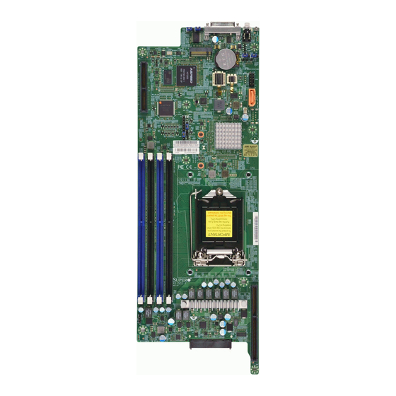
Introduction Congratulations on purchasing your computer motherboard from an industry leader. Supermicro motherboards are designed to provide you with the highest standards in quality and performance. In addition to the motherboard, several important parts that are included with your shipment are listed below. - Page 9 Chapter 1: Introduction Figure 1-1. X11SCE-F Motherboard Image Note: All graphics shown in this manual were based upon the latest PCB revision available at the time of publication of the manual. The motherboard you received may or may not look exactly the same as the graphics shown in this manual.
- Page 10 Super X11SCE-F User's Manual Figure 1-2. X11SCE-F Motherboard Layout (not drawn to scale) Top View Bottom View JPME1 LED5 LED1 JKVM1 JBR1 BMC_HB_LED1 MICRO-LP LED1 JKVM1: USB0/1 JPG1 JPME2 JTPM1 BMC_HB_LED1 I-SATA6 JSD1 JSD1 SRW3 JWD1 SRW3 BAR CODE JBT1...
-
Page 11: Quick Reference Table
Chapter 1: Introduction Quick Reference Table Jumper Description Default Setting JBT1 CMOS Clear Open (Normal) JPG1 VGA Enable Pins 1-2 (Enable) JPME1 ME Recovery Pins 1-2 (Normal) JPME2 Manufacturing Mode Pins 1-2 (Normal) JWD1 Watch Dog Timer Pins 1-2 (Normal) Connector Description Onboard CMOS battery socket... -
Page 12: Motherboard Features
Super X11SCE-F User's Manual Motherboard Features Motherboard Features • Supports an Intel Xeon E-2100 series, 8th Gen Core i3, Pentium, Celeron processors in an LGA1151 socket. Memory • Supports up to 128GB of ECC Very Low Profile (VLP) DIMM with speeds of up to 2666MHz in four slots DIMM Size •... - Page 13 Chapter 1: Introduction Motherboard Features Power Management • Power button override mechanism • Intel Intelligent Power Node Manager (available when the Supermicro Power Manager [SPM] is installed and a special power supply is used) • Management Engine (ME) System Health Monitoring •...
- Page 14 Super X11SCE-F User's Manual Figure 1-3. C246 System Block Diagram PCIe3.0_x8 SVID IMVP8 PCIe x8 MLP SLOT IMVP8 8.0GT/s INTEL LGA1151 SATA-III DDR4 (CHA) DIMMA0 6Gb/s I-SATA[3]/NVMe1 PCIe3.0_x8 2666MHz Socket-H4 PCIe3.0x4 DIMMA1 8.0GT/s 8.0GT/s SATA-III DDR4 (CHB) DIMMB0 6Gb/s I-SATA[4]/NVMe2 2666MHz PCIe3.0x4...
-
Page 15: Processor And Chipset Overview
Chapter 1: Introduction 1.2 Processor and Chipset Overview Built upon the functionality and capability of the Intel Xeon E-2100 series, 8th Generation Core i3, Pentium, Celeron processor, and the C246 chipset, this motherboard provides superb system performance, efficient power management, and a set of features based on cutting edge technology to address the needs of next-generation computer users. -
Page 16: Special Features
Super X11SCE-F User's Manual 1.3 Special Features This section describes the health monitoring features of the X11SCE-F motherboard. The motherboard has an onboard ASpeed 2500 Baseboard Management Controller (BMC) that supports system health monitoring. Recovery from AC Power Loss The Basic I/O System (BIOS) provides a setting that determines how the system will respond when AC power is lost and then restored to the system. -
Page 17: System Resource Alert
Chapter 1: Introduction System Resource Alert This feature is available when used with SuperDoctor 5 . SuperDoctor 5 is used to notify the ® user of certain system events. For example, you can configure SuperDoctor 5 to provide you with warnings when the system temperature, CPU temperatures, voltages and fan speeds go beyond a predefined range. -
Page 18: Advanced Power Management
Intelligent Power Node Manager (IPNM) ® Available when the Supermicro Power Manager (SPM) is installed, Intel's Intelligent Power Node Manager (IPNM) provides your system with real-time thermal control and power management for maximum energy efficiency. Although IPNM Specification Version 2.0/3.0 is supported by the BMC (Baseboard Management Controller), your system must also have IPNM-compatible Management Engine (ME) firmware installed to use this feature. -
Page 19: Chapter 2 Installation
Chapter 2: Installation Chapter 2 Installation 2.1 Static-Sensitive Devices Electrostatic Discharge (ESD) can damage electronic com ponents. To avoid damaging your motherboard and your system, it is important to handle it very carefully. The following measures are generally sufficient to protect your equipment from ESD. Precautions •... -
Page 20: Motherboard Installation
Super X11SCE-F User's Manual 2.2 Motherboard Installation All motherboards have standard mounting holes to fit different types of chassis. Make sure that the locations of all the mounting holes for both the motherboard and the chassis match. Although a chassis may have both plastic and metal mounting fasteners, metal ones are highly recommended because they ground the motherboard to the chassis. -
Page 21: Installing The Motherboard Into The Mounting Tray
Chapter 2: Installation Installing the Motherboard into the Mounting Tray 1. Locate the mounting holes on the motherboard and the mounting tray. See the previous page for the location. 2. Install the standoffs on the mounting tray. Align the mounting holes on the motherboard against the mounting holes on the tray. -
Page 22: Installing The Motherboard Into The Microblade Chassis
Super X11SCE-F User's Manual Installing the Motherboard into the Microblade Chassis 1. When the motherboard is securely installed on the mounting tray, push the tray into the Microblade chassis as shown below. 2. Once the mounting tray is pushed into the chassis, the connectors on the motherboard's edge will make contact with the chassis backplane, which provides the connections to the chassis power, network, and other I/O devices. -
Page 23: Processor And Heatsink Installation
CPU socket cap is in place and none of the socket pins are bent; otherwise, contact your retailer immediately. • Refer to the Supermicro website for updates on CPU support. Installing the LGA1151 Processor 1. Press the load lever down to release the load plate from its locking position. - Page 24 Super X11SCE-F User's Manual 2. Gently lift the load lever to open the load plate. Remove the plastic protective cover. Do not touch the CPU socket contacts. 3. Locate the triangle on the CPU and CPU socket, which indicates the location of Pin 1.
- Page 25 Chapter 2: Installation 5. Close the load plate, then gently push down the load lever into its locking position. CPU properly installed Load lever locked into place Note: You can only install the CPU in one direction. Make sure it is properly inserted into the socket before closing the load plate.
-
Page 26: Installing A Passive Cpu Heatsink
Super X11SCE-F User's Manual Installing a Passive CPU Heatsink 1. Do not apply thermal grease to the heatsink or the CPU; the required amount has already been applied. 2. Align the four holes of the heatsink with the four mounting holes on the motherboard. -
Page 27: Removing The Heatsink
Chapter 2: Installation Removing the Heatsink Note: We do not recommend that the CPU or heatsink be removed. However, if you do need to remove the heatsink, please follow the instructions below to remove the heatsink and prevent damage done to the CPU or other components. 1. -
Page 28: Memory Support And Installation
Super X11SCE-F User's Manual 2.4 Memory Support and Installation Memory Support The motherboard supports up to 128GB of ECC Very Low Profile (VLP) DIMM with speeds of up to 2666MHz in four slots. Populating the DIMM slots with pairs of memory modules of the same type, speed and size will result in interleaved memory, which improves performance. -
Page 29: Dimm Installation
3. Align the key of the DIMM module with the receptive point on the memory slot. 4. Align the notches on both ends of the module against the receptive points on the X11SCE-F ends of the slot. REV:1.02 DESIGNED IN USA 5. -
Page 30: Connectors
Super X11SCE-F User's Manual 2.5 Connectors TPM Header The JTPM1 header is used to connect a Trusted Platform Module (TPM)/Port 80, which is available from a third-party vendor. A TPM/Port 80 connector is a security device that supports encryption and authentication in hard drives. It allows the motherboard to deny access if the TPM associated with the hard drive is not installed in the system. - Page 31 It also provides a VGA connection, serial port connection, and two USB 2.0 connections (USB0/1). 1. KVM Connector JKVM1: USB0/1 BMC_HB_LED1 JSD1 SRW3 BAR CODE BIOS MAC CODE JBT1 LICENSE SRW4 X11SCE-F REV:1.02 DESIGNED IN USA...
- Page 32 Super X11SCE-F User's Manual Backplane Connector The backplane connector at J22 provides four SATA 3.0 connections or two NVMe PCI-E 3.0 x4 connections. Disk On Module Power Connector The Disk On Module (DOM) power connector at JSD1 provides 5V power to a solid state DOM storage device connected to the I-SATA0 port.
- Page 33 Chapter 2: Installation I-SATA 3.0 Ports The X11SCE-F has two I-SATA 3.0 ports via the backplane (I-SATA0), one via the right angle receptor connector. These SATA ports are supported by the C246 chipset. I-SATA6 can be used with Supermicro SuperDOMs that are yellow SATA DOM connectors with power pins built in, and do not require external power cables.
- Page 34 Super X11SCE-F User's Manual Power Button Press the button at SW2 to power on the motherboard. This button can also power off the motherboard instantly or in four seconds. The settings for this button can be configured with the Power Button Function feature in the BIOS.
- Page 35 Pin Definitions Pin# Definition Color Status Ground Blue: On Unit Identified Ground Button In Button In 1. UID Switch JKVM1: USB0/1 2. UID LED BMC_HB_LED1 JSD1 SRW3 BAR CODE MAC CODE BIOS JBT1 LICENSE SRW4 X11SCE-F REV:1.02 DESIGNED IN USA...
-
Page 36: Jumper Settings
Super X11SCE-F User's Manual 2.6 Jumper Settings How Jumpers Work To modify the operation of the motherboard, jumpers can be used to choose between optional settings. Jumpers create shorts between two pins to change the function of the connector. Pin 1 is identified with a square solder pad on the printed circuit board. See the diagram at right for an example of jumping pins 1 and 2. - Page 37 6. Replace the cover, reconnect the power cord(s), and power on the system. Note: Clearing CMOS will also clear all passwords. JKVM1: USB0/1 JBT1 contact pads BMC_HB_LED1 JSD1 1. Clear CMOS SRW3 BAR CODE MAC CODE BIOS JBT1 LICENSE SRW4 X11SCE-F REV:1.02 DESIGNED IN USA...
- Page 38 Super X11SCE-F User's Manual Management Engine (ME) Recovery Use jumper JPME1 to select ME Firmware Recovery mode, which will limit resource allocation for essential system operation only in order to maintain normal power operation and management. In the single operation mode, online upgrade will be available via Recovery mode.
- Page 39 Use jumper JPG1 to enable or disable the VGA port using the onboard graphics controller. VGA Enable/Disable Jumper Settings Jumper Setting Definition Pins 1-2 Enabled (Default) Pins 2-3 Disabled JKVM1: USB0/1 1. VGA Enable/Disable BMC_HB_LED1 JSD1 SRW3 BAR CODE BIOS MAC CODE JBT1 LICENSE SRW4 X11SCE-F REV:1.02 DESIGNED IN USA...
- Page 40 Super X11SCE-F User's Manual Watch Dog JWD1 controls the Watch Dog function. Watch Dog is a monitor that can reboot the system when a software application hangs. Jumping pins 1-2 will cause Watch Dog to reset the system if an application hangs. Jumping pins 2-3 will generate a non-maskable interrupt signal for the application that hangs.
-
Page 41: Led Indicators
LED Indicator LED Color Definition Solid Overheat Fan Failure or Power Blinking Failure JKVM1: USB0/1 1. BMC Heartbeat LED 2. Overheat/Fan Failure/Power Failure LED BMC_HB_LED1 JSD1 SRW3 BAR CODE MAC CODE BIOS JBT1 LICENSE SRW4 X11SCE-F REV:1.02 DESIGNED IN USA... -
Page 42: Chapter 3 Troubleshooting
Super X11SCE-F User's Manual Chapter 3 Troubleshooting 3.1 Troubleshooting Procedures Use the following procedures to troubleshoot your system. If you have followed all of the procedures below and still need assistance, refer to the ‘Technical Support Procedures’ and/ or ‘Returning Merchandise for Service’ section(s) in this chapter. Always disconnect the AC power cord before adding, changing or installing any non hot-swap hardware components. -
Page 43: Memory Errors
Chapter 3: Troubleshooting Memory Errors 1. Make sure that the DIMM modules are properly and fully installed. 2. Confirm that you are using the correct memory. Also, it is recommended that you use the same memory type and speed for all DIMMs in the system. See Section 2.4 for memory details. - Page 44 Super X11SCE-F User's Manual 2. Memory support: Make sure that the memory modules are supported by testing the modules using memtest86 or a similar utility. Note: Click on the Tested Memory List link on the motherboard product page to see a list of supported memory.
-
Page 45: Technical Support Procedures
Chapter 3: Troubleshooting 3.2 Technical Support Procedures Before contacting Technical Support, please take the following steps. Also, note that as a motherboard manufacturer, we do not sell directly to end-users, so it is best to first check with your distributor or reseller for troubleshooting services. They should know of any possible problem(s) with the specific system configuration that was sold to you. -
Page 46: Frequently Asked Questions
Question: What type of memory does my motherboard support? Answer: The X11SCE-F motherboard supports up to 128GB of ECC Very Low Profile (VLP) DIMM with speeds of up to 2666MHz in four slots. See Section 2.4 for details on installing memory. -
Page 47: Battery Removal And Installation
Chapter 3: Troubleshooting 3.4 Battery Removal and Installation Battery Removal To remove the onboard battery, follow the steps below: 1. Power off your system and unplug your power cable. 2. Using a tool such as a pen or a small screwdriver, push the battery lock outwards to unlock it. -
Page 48: Returning Merchandise For Service
Super X11SCE-F User's Manual 3.5 Returning Merchandise for Service A receipt or copy of your invoice marked with the date of purchase is required before any warranty service will be rendered. You can obtain service by calling your vendor for a Returned Merchandise Authorization (RMA) number. -
Page 49: Chapter 4 Uefi Bios
UEFI BIOS 4.1 Introduction This chapter describes the AMIBIOS™ Setup utility for the X11SCE-F motherboard. The BIOS is stored on a chip and can be easily upgraded using a flash program. Note: Due to periodic changes to the BIOS, some settings may have been added or deleted and might not yet be recorded in this manual. -
Page 50: Main Setup
Super X11SCE-F User's Manual 4.2 Main Setup When you first enter the AMI BIOS setup utility, you will enter the Main setup screen. You can always return to the Main setup screen by selecting the Main tab on the top of the screen. - Page 51 Chapter 4: BIOS Memory Information Total Memory This feature displays the total size of memory available in the system.
-
Page 52: Advanced
Super X11SCE-F User's Manual 4.3 Advanced Use this menu to configure advanced settings. Warning: Take caution when changing the Advanced settings. An incorrect value, a very high DRAM frequency or an incorrect BIOS timing setting may cause the system to malfunction. - Page 53 Chapter 4: BIOS Option ROM Messages Use this feature to set the display mode for the Option ROM. Select Keep Current to display the current AddOn ROM setting. Select Force BIOS to use the Option ROM display set by the system BIOS. The options are Force BIOS and Keep Current. Wait For "F1"...
- Page 54 Super X11SCE-F User's Manual CPU Configuration The following CPU information will display: • Processor type • CPU Signature • Microcode Revision • CPU Speed • L1 Data Cache • L1 Instruction Cache • L2 Cache • L3 Cache •...
- Page 55 Chapter 4: BIOS Intel (VMX) Virtualization Technology Use this feature to enable the Vanderpool Technology. This technology allows the system to run several operating systems simultaneously. The options are Disabled and Enabled. Active Processor Cores This feature determines how many CPU cores will be activated for each CPU. When all is selected, all cores in the CPU will be activated.
- Page 56 Super X11SCE-F User's Manual Monitor/Mwait Select Enable to enable the Monitor/Mwait instructions. The Monitor instructions monitors a region of memory for writes, and MWait instructions instruct the CPU to stop until the monitored region begins to write. The options are Disabled and Enabled.
- Page 57 Chapter 4: BIOS Chipset Configuration Warning: Setting the wrong values in the sections below may cause the system to malfunction. System Agent (SA) Configuration The following information will display: • SA PCIe Code Version • VT-d Memory Configuration Memory Configuration •...
- Page 58 Super X11SCE-F User's Manual Fast Boot Use this feature to enable or disable fast path through the memory reference code. The options are Disabled and Enabled. REFRESH_2X_MODE (Available if supported by the CPU) Use this feature to select the refresh mode. The options are Disabled, 1-Enabled for WARM or HOT, and 2-Enabled HOT only.
- Page 59 Chapter 4: BIOS Max Link Width Use this feature to select the PEG link for the specified port. The options are Auto, Force X1, Force X2, Force X4, and Force X8. ASPM (Available if a graphics card is detected) Use this feature to activate the Active State Power Management (ASPM) level for a PCI- E device.
- Page 60 Super X11SCE-F User's Manual Internal Graphics Select Auto to keep an internal graphics device installed on an expansion slot supported by the CPU to be automatically enabled. The options are Auto, Disabled, and Enabled. VT-d Select Enabled to activate Intel Virtualization Technology support for Direct I/O VT-d by reporting the I/O device assignments to VMM through the DMAR ACPI Tables.
- Page 61 Chapter 4: BIOS Super IO Configuration Super IO Configuration Super IO Chip AST2500 Serial Port 1 Configuration Serial Port Select Enabled to enable the selected onboard serial port. The options are Disabled and Enabled. Device Settings This feature displays the status of a serial port specified by the user. Change Settings This feature specifies the base I/O port address and the Interrupt Request address of a serial port specified by the user.
- Page 62 Super X11SCE-F User's Manual Serial Port Console Redirection COM1 Console Redirection Select Enabled to enable COM1 for Console Redirection, which will allow a client machine to be connected to a host machine at a remote site for networking. The options are Disabled and Enabled.
- Page 63 Chapter 4: BIOS Stop Bits A stop bit indicates the end of a serial data packet. Select 1 Stop Bit for standard serial data communication. Select 2 Stop Bits if slower devices are used. The options are 1 and 2. Flow Control Use this feature to set the flow control for Console Redirection to prevent data loss caused by buffer overflow.
- Page 64 Super X11SCE-F User's Manual *If the feature above is set to Enabled, the following features will become available for configuration: Console Redirection Settings COM1 Console Redirection Settings Terminal Type This feature allows the user to select the target terminal emulation type for Console Redirection.
- Page 65 Chapter 4: BIOS Flow Control Use this feature to set the flow control for Console Redirection to prevent data loss caused by buffer overflow. Send a "Stop" signal to stop sending data when the receiving buffer is full. Send a "Start" signal to start sending data when the receiving buffer is empty. The options are None and Hardware RTS/CTS.
- Page 66 Super X11SCE-F User's Manual Redirection After Post Use this feature to enable or disable legacy console redirection after BIOS POST. When set to BootLoader, legacy console redirection is disable before booting the OS. When set to Always Enable, legacy console redirection remains enabled when booting the OS. The options are Always Enable and BootLoader.
- Page 67 Chapter 4: BIOS Data Bits Parity Stop Bits SATA And RSTe Configuration SATA Controller(s) This feature enables or disables the onboard SATA controller supported by the Intel PCH chip. The options are Enabled and Disabled. SATA Mode Selection Select AHCI to configure a SATA drive specified by the user as an AHCI drive. Select RAID to configure a SATA drive specified by the user as a RAID drive.
- Page 68 Super X11SCE-F User's Manual Serial ATA Port 0~7 Hot Plug Set this feature to Enable for hot plug support, which will allow the user to replace a SATA drive without shutting down the system. The options are Disabled and Enabled.
- Page 69 Chapter 4: BIOS Native PCIE Enable Enable this feature to grant native control of hot plug, Power Management Events, PCI-E Advanced Error Reporting, PCI-E Capability Structure Control, and Latency Tolerance Reporting Control. The options are Disabled and Enabled. Native ASPM Select Enabled for the operating system to control the Active State Power Management (ASPM).
- Page 70 Super X11SCE-F User's Manual PCIe/PCI/PnP Configuration Option ROM execution PCI PERR/SERR Support Use this feature to enable or disable the runtime event for PCI errors. The options are Disabled and Enabled. Above 4G MMIO BIOS Assignment Select Enabled to decode a PCI device that supports 64-bit in the space above 4G Address.
- Page 71 Chapter 4: BIOS Security Device Support If this feature and the TPM jumper on the motherboard are both set to Enabled, onboard security devices will be enabled for TPM support to enhance data integrity and network security. Please reboot the system for a change on this setting to take effect. The options are Disable and Enable.
- Page 72 TPM 2.0 will restrict support for TPM 2.0 devices. Select Auto to enable support for both versions. The options are TPM 1.2, TPM 2.0, Auto. SMCI BIOS-Based TPM Provision Support Use this feature to enable the Supermicro TPM Provision support. The options are Disabled and Enabled. TXT Support Intel Trusted Execution Technology (TXT) helps protect against software-based attacks and ensures protection, confidentiality, and integrity of data stored or created on the system.
- Page 73 Chapter 4: BIOS iSCSi Configuration iSCSI Initiator Name This feature allows the user to enter the unique name of the iSCSI Initiator in IQN format. Once the name of the iSCSI Initiator is entered into the system, configure the proper settings for the following items.
-
Page 74: Event Logs
Super X11SCE-F User's Manual 4.4 Event Logs Use this menu to configure event log settings. Change SMBIOS Event Log Settings Enabling/Disabling Options SMBIOS Event Log Change this feature to enable or disable all features of the SMBIOS Event Logging during system boot. - Page 75 Chapter 4: BIOS SMBIOS Event Log Standard Settings Log System Boot Event Select Enabled to log system boot events. The options are Enabled and Disabled. MECI (Multiple Event Count Increment) Enter the increment value for the multiple event counter. Enter a number between 1 to 255. The default setting is 1.
-
Page 76: Ipmi
Super X11SCE-F User's Manual 4.5 IPMI Use this menu to configure Intelligent Platform Management Interface (IPMI) settings. BMC Firmware Revision This feature indicates the IPMI firmware revision in your system. IPMI STATUS This feature indicates the status of the IPMI firmware installed in your system. - Page 77 Chapter 4: BIOS When SEL is Full This feature allows the user to determine what the BIOS should do when the system event log is full. Select Erase Immediately to erase all events in the log when the system event log is full.
- Page 78 Super X11SCE-F User's Manual Station MAC Address This feature displays the Station MAC address for this computer. Mac addresses are 6 two-digit hexadecimal numbers. Gateway IP Address This feature displays the Gateway IP address for this computer. This should be in decimal and in dotted quad form (i.e., 192.168.10.253).
-
Page 79: Security
Chapter 4: BIOS 4.6 Security Use this menu to configure the security settings for the system. Password Check Select Setup for the system to check for a password at Setup. Select Always for the system to check for a password at bootup or upon entering the BIOS Setup utility. The options are Setup and Always. - Page 80 Super X11SCE-F User's Manual Secure Boot Mode This feature allows the user to select the desired secure boot mode for the system. The options are Standard and Custom. *If Secure Boot Mode is set to Customized, Key Management features are available...
- Page 81 Chapter 4: BIOS Key Exchange Keys Update Select Yes to load a factory default KEK or No to load from a file on an external media. Append Select Yes to add the KEK from the manufacturer's defaults list to the existing KEK. Select No to load the KEK from a file.
-
Page 82: Boot
Super X11SCE-F User's Manual 4.7 Boot Use this menu to configure boot settings. Setup Prompt Timeout Use this feature to specify the length of time (the number of seconds) for the BIOS to wait before rebooting the system when the setup activation key is pressed. Enter the value of 65535 (0xFFFF) for the BIOS to wait indefinitely. - Page 83 Chapter 4: BIOS boot from. Press <Enter> on each entry from top to bottom to select devices. • LEGACY/UEFI/DUAL Boot Order #1 • LEGACY/UEFI/DUAL Boot Order #2 • LEGACY/UEFI/DUAL Boot Order #3 • LEGACY/UEFI/DUAL Boot Order #4 • LEGACY/UEFI/DUAL Boot Order #5 •...
-
Page 84: Save & Exit
Super X11SCE-F User's Manual 4.8 Save & Exit Use this menu to configure save and exit settings. Save Options Discard Changes and Exit Select this option to quit the BIOS Setup without making any permanent changes to the system configuration and reboot the computer. Select Discard Changes and Exit from the Exit menu and press <Enter>. - Page 85 Chapter 4: BIOS Default Options Restore Defaults To set this feature, select Restore Optimized Defaults and press <Enter>. These are factory settings designed for maximum system performance but not for maximum stability. Save as User Defaults To set this feature, select Save as User Defaults from the Exit menu and press <Enter>. This enables the user to save any changes to the BIOS setup for future use.
-
Page 86: Appendix A Software Installation
The Supermicro website contains drivers and utilities for your system at https://www. supermicro.com/wftp/driver. Some of these must be installed, such as the chipset driver. After accessing the website, go into the CDR_Images (in the parent directory of the above link) and locate the ISO file for your motherboard. Download this file to create a DVD of the drivers and utilities it contains. -
Page 87: Superdoctor 5
SATA settings back to your original settings. A.2 SuperDoctor ® The Supermicro SuperDoctor 5 is a hardware monitoring program that functions in a command-line or web-based interface in Windows and Linux operating systems. The program monitors system health information such as CPU temperature, system voltages, system power consumption, fan speed, and provides alerts via email or Simple Network Management Protocol (SNMP). -
Page 88: Appendix B Standardized Warning Statements
The following statements are industry standard warnings, provided to warn the user of situations which have the potential for bodily injury. Should you have questions or experience difficulty, contact Supermicro's Technical Support department for assistance. Only certified technicians should attempt to install or configure components. - Page 89 Appendix B: Standardized Warning Statements Attention Danger d'explosion si la pile n'est pas remplacée correctement. Ne la remplacer que par une pile de type semblable ou équivalent, recommandée par le fabricant. Jeter les piles usagées conformément aux instructions du fabricant. ¡Advertencia! Existe peligro de explosión si la batería se reemplaza de manera incorrecta.
- Page 90 Super X11SCE-F User's Manual Product Disposal Warning! Ultimate disposal of this product should be handled according to all national laws and regulations. 製品の廃棄 この製品を廃棄処分する場合、 国の関係する全ての法律 ・ 条例に従い処理する必要があります。 警告 本产品的废弃处理应根据所有国家的法律和规章进行。 警告 本產品的廢棄處理應根據所有國家的法律和規章進行。 Warnung Die Entsorgung dieses Produkts sollte gemäß allen Bestimmungen und Gesetzen des Landes erfolgen.
-
Page 91: Appendix C Uefi Bios Recovery
Warning: Do not upgrade the BIOS unless your system has a BIOS-related issue. Flashing the wrong BIOS can cause irreparable damage to the system. In no event shall Supermicro be liable for direct, indirect, special, incidental, or consequential damages arising from a BIOS update. -
Page 92: Recovering The Main Bios Block With A Usb Device
Super X11SCE-F User's Manual C.3 Recovering the Main BIOS Block with a USB Device This feature allows the user to recover the main BIOS image using a USB-attached device without additional utilities used. A USB flash device such as a USB Flash Drive, or a USB CD/DVD ROM device can be used for this purpose. - Page 93 Appendix C: UEFI BIOS Recovery 3. After locating the healthy BIOS binary image, the system will enter the BIOS Recovery menu as shown below. Note: At this point, you may decide if you want to start the BIOS recovery. If you decide to proceed with BIOS recovery, follow the procedures below.
- Page 94 Super X11SCE-F User's Manual 5. After the BIOS recovery process is complete, press any key to reboot the system. 6. Using a different system, extract the BIOS package into a USB flash drive. 7. Press <Del> continuously during system boot to enter the BIOS Setup utility. From the top of the tool bar, select Boot to enter the submenu.
- Page 95 Appendix C: UEFI BIOS Recovery 8. When the UEFI Shell prompt appears, type fs# to change the device directory path. Go to the directory that contains the BIOS package you extracted earlier from Step 6. Enter flash.nsh BIOSname.### at the prompt to start the BIOS update process. Note: Do not interrupt this process until the BIOS flashing is complete.
Need help?
Do you have a question about the X11SCE-F and is the answer not in the manual?
Questions and answers