Table of Contents
Advertisement
Quick Links
Advertisement
Table of Contents

Related Manuals for AMX DCP-MTX


Summary of Contents for AMX DCP-MTX
- Page 1 USER MANUAL DCP-MTX 100m 4K HDBaseT Daisy-Chain Presentation Switcher...
-
Page 2: Table Of Contents
8.2 Web UI .......................22 8.2.1 Log Into Web UI ................22 8.2.2 Control Through Web UI ..............23 8.2.2.1 Status ..................25 8.2.2.2 Configuration .................25 8.2.2.3 Advanced ................33 8.2.2.4 Device List ................38 8.3 Telnet ......................39 9. RESET ........................40 APPENDIX: API COMMAND SET ................41 USER MANUAL DCP-MTX... -
Page 3: Important Safety Instructions
Protect the power cord from lightning storms or when un- being walked on or pinched used for long periods of time. particularly at plugs. Only use attachments/accesso- Refer all servicing to qualified ries specified by the manufac- service personnel. turer. USER MANUAL DCP-MTX... -
Page 4: Introduction
HDBaseT up to 100 meters and supports cascade connection of multiple A/V sources, displays or any devices capable of HDBaseT transmission. DCP-MTX accepts video signals from HDMI IN, Display Port IN or VGA IN as well as embedded audio signal from a 3.5 mm AUDIO IN port and cascades selected signal through HDBaseT. -
Page 5: Packing List
2. PACKING LIST 1 x DCP-MTX 1 x Power Supply (12 DVC, 3A) 3 x Phoenix Male Connectors (3.5 mm, 3 pins) 2 x Phoenix Male Connectors (3.5 mm, 4 pins) 2 x Mounting Brackets ... -
Page 6: Specifications
1366 x 768@60Hz, 1440 x 900@60Hz, 1600 x 900@60Hz, 1600 x 1200@60Hz, 1680 x 1050@60Hz, 1920 x 1080@60Hz, 1920 x 1200@60Hz, 1280 x 720P@50Hz, 1280 x 720P@60Hz, 1920 x 1080P@50Hz, 1920 x 1080P@60Hz, Note: HDBaseT OUT: HDMI with 4k@60Hz (Chroma sub-sampling 4:2:0 8-bit only) USER MANUAL DCP-MTX... - Page 7 ±8kV (air-gap discharge) • ±4kV (contact discharge) Power Supply 12 VDC, 3A Power Consumption 20.52 W (Maximum) Dimensions (W x H x D) 223 mm x 27 mm x 124.2 mm Weight 0.8 kg Certification CE, FCC USER MANUAL DCP-MTX...
-
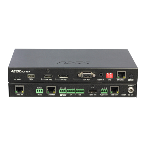
Page 8: Panel Overview
Uses a DIP switch for EDID management. Connects to a LAN device, e.g. laptop, for LAN accesss or ETHERNET Web control. Uses this button to switch active input signal, activate / MYTURN button de-activate the device in a system or execute IP sequencing. USER MANUAL DCP-MTX... -
Page 9: Rear Panel
Connects to an audio system, e.g. amplifier. Connects to HDBT IN of any HDBT device or another DCP- HDBT OUT MTX. RESET button Resets the device to factory default settings. DC 12V Connects to the power adapter provided. USER MANUAL DCP-MTX... -
Page 10: Edid Switch
EDID (Extended Display Identification Data) is a data structure provided by a digital display to describe its capabilities to a video source. DCP-MTX features an EDID management that can be used when the EDID setting’s does not meet the installation requirements. -
Page 11: Application & Installation
Activate any of the “transmitter” DCP-MTXs’ MYTURN button, displays connected to “receiver” DCP-MTXs will display the activated device’s active signal. Example: if DCP-MTX 3’s MYTURN is activated, Display x, y and z will present active signal from DCP-MTX 3. Chain Mode Connection (without local display) - Page 12 SOURCE 3 Application 3: Ring Mode In the Ring mode, all the DCP-MTXs are connected to one another. When any DCP-MTX with active input signal is MYTURN activated, all the displays will show its active signal. Example: if DCP-MTX 3 is MYTURN activated, Display 1 to Z will show active signal from DCP-MTX 3.
-
Page 13: Installation & Connection
“SYSTEM WIRING” chart: 1. Connect DCP-MTXs through HDBT: 1) Connect HDBT OUT of the first DCP-MTX to HDBT IN of the next (e.g. DCP- MTX 1 to DCP-MTX 2); 2) Connect the rest DCP-MTXs through HDBT likewise. - Page 14 For information about accessing and operating Web UI, please refer to “8.2 WEB UI”. • To avoid IP addressing conflicts, please repeat Step 2 if any DCP-MTX is reset, removed from and added to the connection. • To make CEC control effective, please use CEC-enabled display devices.
- Page 15 USER MANUAL DCP-MTX...
- Page 16 USER MANUAL DCP-MTX...
-
Page 17: Cec & Rs232 Auto Control
DCP-MTX is embedded with a CEC controller and a RS232 controller. When CEC / RS232 Auto Control is switched on, DCP-MTX will detect the signal status and send CEC / RS232 command to power on or off the display connected. CEC / RS232 Auto Control of DCP-MTX can be configured through Web UI or Telnet. - Page 18 2) If any active input signal is inserted in the middle of countdown, the countdown will cancel automatically. Display MYTURN Activated HDBaseT HDBaseT DCP-MTX Display The display connected HDBaseT HDBaseT will shutdown DCP-MTX Display Detect for active input signal Start to countdown if...
- Page 19 NOTE: • CEC/RS232 Auto Control is effective where input signal changes and is not applicable for a MYTURN activated DCP-MTX with no input signal, even if a display sink is connected. • To realize CEC/RS232 Auto Control of DCP-MTX, please connect a display device which accepts CEC/RS232 command.
-
Page 20: Set-Up & Control
1) Long press MYTURN button of the first DCP-MTX, or DCP-MTX 1 in the chart below, in the connection system for 10 seconds; 2) The input LEDs (HDMI IN, DP IN & VGA IN ) of DCP-MTX 1 will flash twice. 3) Then DCP-MTX 1 will start IP sequencing automatically and the rest DCP-MTXs will get their individual IP address according to their sequence in the connection loop (for instance, if DCP-MTX 1 gets 192.168.1.121 (Default IP address of DCP-... - Page 21 (if there’s any)and downstream displays (for a Chain Mode connection) or all displays (for a Ring Mode connection). • Auto Switch Mode: if the DCP-MTX selected is in Auto Switch Mode, the first detected input signal (HDMI IN → DP IN → VGA IN) will be in active use immediately after the short press of its MYTURN button.
-
Page 22: Web Ui
DCP-MTX or a DCP system with great ease and convenience. The Web UI can be accessed through a modern browser, e.g. Chrome, Safari, Firefox, etc. DCP-MTX ships with a default IP address of 192.168.1.121 and default login password for Wen UI of admin. 8.2.1 Log Into WEB UI To get accessed to Web UI of DCP-MTX, please follow the instructions below. -
Page 23: Control Through Web Ui
TIP: In case you forget the IP address or the login password newly changed for DCP-MTX, please reset the device using the “RESET” button. For more information, please go to “9. RESET”. 8.2.2 Control through WEB UI Web UI of DCP-MTX is comprised by four sections: Status, Configuration, Advanced, and Device List. - Page 24 Custom Web UI Logo Factory Default Change Password System Advanced Reboot System Enable (ON/OFF) Automatic Logout Delay Time Firmware Firmware (MCU & ARM) Device 1 (Name, IP) Device List Device 2 (Name, IP) Device n (Name, IP) USER MANUAL DCP-MTX...
-
Page 25: Status
DCP-MTX will show such information as Name, IP Address, Sequence, Grouping, Select (input source signal). A click of DCP-MTX will pop up the following window, which allow you to verify and switch for desired input signal for the selected DCP-MTX. - Page 26 The ID button is used to help located the DCP-MTX in a DCP connection system. Click to turn ON the ID button, then check the ID LED of each DCP-MTX or DCP device. The device with a flashing ID LED is the one accessed through Web UI.
- Page 27 3, the above connection status will appear after reloading. 2. If any DCP-MTX or DCP device is reset, removed from or added to the connection, please repeat the above steps to reset IP sequencing to avoid IP conflicts among connected devices.
- Page 28 DCP-MTX or the system. 6) Network The Network section allows you to set up the IP mode of the DCP-MTX to either Static or DHCP. By default, DCP-MTX is shipping in Static mode, with default IP address of 192.168.1.121, Netmask of 255.255.0.0 and Gateway of 192.168.1.1.
- Page 29 The Auto Switch section enables or disable Auto Switch of the DCP-MTX. If Auto Switch is turned ON: • If a new input source signal is detected, DCP-MTX will automatically switch to use the new input signal. • If an active source is removed or its output is disabled, DCP-MTX will automatically switch to another active input signal by checking its priority (Priority from the highest to the lowest: HDMI IN, DP IN, VGA IN).
- Page 30 3) EDID By default, the EDID setting of DCP-MTX is in 1920 x 1080@60Hz 2CH mode (the EDID DIP switch is set to 0 0 1 0). To adjust EDID settings of DCP-MTX through Web UI, please manually set the EDID switch on the front panel to 1 0 0 1.
- Page 31 CEC Manual Control: Click to turn on or off the display manually. 2) RS232 Controller DCP-MTX incorporates a built-in RS232 controller and is able to power on or off the display connected to RS232 port by detecting the source status and then sending corresponding command to the display.
- Page 32 RS232 Auto Control: Click to enable or disable RS232 Auto Control. When enabled, DCP-MTX will send a RS232 command to turn off the display connected to its RS232 port when there’s no signal present after a defined Delay Time or turn it on immediately when there’s active signal.
-
Page 33: Advanced
The Advanced section includes Welcome Menu, Password, System, Fireware and allows you to customize your own logo for your Web UI pages, set up a new login password, reset or reboot the DCP-MTX settings, enable/disable automatic logout from Web UI and upgrade firmware of your DCP-MTX device. - Page 34 MTX, please reset the device using the “RESET” button on the rear panel. For more information, please go to “9. RESET”. System The System section is for resetting and rebooting the DCP-MTX device as well as setting the Automatic Logout from the Web UI. 1) System The System sub-section is used for restoring the DCP-MTX to factory default settings or rebooting the system.
- Page 35 Step 2: Click “Browse” to search for the update file. Then click “Next” to start uploading the update files. NOTE: Please mind the suffix (.h00 / .h01 / .h02) of each update file and ensure each file goes to the correct data bank. Otherwise you may fail to start upgrading. USER MANUAL DCP-MTX...
- Page 36 Step 5: When completed, the following window will appear. After completion, please reboot the device manually. 2) To upgrade ARM To upgrade ARM, please follow the instructions below: Step 1: Click ARM “Update” button, then the following window will pop up. USER MANUAL DCP-MTX...
- Page 37 Step 2: Click “Browse” to search for the update file. Then click “Next” to start uploading the update files. Step 3: When uploading is done, the following appears. Click “Next” to start updating. USER MANUAL DCP-MTX...
-
Page 38: Device List
The Device List section lists out all the connected DCP devices by showing their model name and IP address. • Refresh: Click to refresh the Device List. • Listed Device: Click to navigate to its Web UI page. USER MANUAL DCP-MTX... -
Page 39: Telnet
8.3 TELNET DCP-MTX can also be controlled by Telnet, a protocol that enables you to connected a remote or local computer with DCP-MTX over a TCP/IP network. Before controlling or setting up DCP-MTX through Telnet, please ensure the Telnet connection between the controlling device (e.g. PC) and DCP-MTX has been configured correctely. -
Page 40: Reset
9. RESET DCP-MTX installs a physical RESET button on its rear panel and will restore the device settings and login password. To reset DCP-MTX: 1. Hold down the RESET button (rear panel) for at least 5 seconds using a paper clip. -
Page 41: Appendix: Api Command Set
Get the Mapping Status for Parameter: Description: Outputs and Inputs ※ value = {1, 2, 3, 4} // {1, 2, 3, HDMI input is mapped to all 4}:{hdmi, dp, vga,hdbt} outputs Description: Get which input is mapped to all outputs USER MANUAL DCP-MTX... - Page 42 Get MYTURN signal. Command: Command: SRMAKT SRMAKT Return: Return: SRMAKT( value ) SRMAKT( 1 ) Get Ring marker Parameter: Description: ※ value = {0, 1} // {0, 1}:{false, true} Ring Marker is true. Description: Get Ring Marker USER MANUAL DCP-MTX...
- Page 43 Description: Get Sort Ungrouping. Command: Command: CSORP#T CSORP1T Return: Return: CSORP#T CSORP1T Set MYTURN Sort Protection Parameter: Description: ※ P# = {0, 1} // {0, 1}:{off, on} Set MYTURN Sort protection on. Description: Set MYTURN Sort protection. USER MANUAL DCP-MTX...
- Page 44 CSPA1T Return: Return: CSPA#T CSPA1T Set CEC Auto Power On/Off Parameter: Description: ※ SPA# : # = {0, 1} // {0, 1}:{off, on} Set sink auto power on. Description: Set sink auto power Function ON or OFF USER MANUAL DCP-MTX...
- Page 45 Get CEC POWER Delay Time Status. Command: Command: CUBD#T CUBD115200T Return: Return: CUBD#T CUBD115200T Set UART Baud Rate Parameter: Description: ※ SOR# : # = {9600, 19200, 38400, UART Baud Rate is 115200. 57600, 115200} Description: Set UART Baud Rate. USER MANUAL DCP-MTX...
- Page 46 {hex1 hex2 … hex64}:{hex1, hex2… projector. hex64, is ASC II string of hex value. For example, string “123”, convert to correct format string is“31 32 33”} Description: Hex UART Command Edit USER MANUAL DCP-MTX...
- Page 47 Return: Return: SUAUT( value ) SUAUT( 1 ) Get UART Auto Power Status Parameter: Description: ※ value = {0, 1} // {0, 1}:{off, on} Get UART Auto Power Status is on. Description: Get UART Auto Power Status. USER MANUAL DCP-MTX...
- Page 48 Set Inputs support HDCP or not. Command: SI#DCPT Return: SI#DCPT( value ) Get Input HDCP Support Status Parameter: ※ I# : # = {1} // {1}:{hdmi} ※ value = {0, 1} // {0, 1}:{off, on} Description: Get Input HDCP Support Status. USER MANUAL DCP-MTX...
- Page 49 Set All Input EDID 0011->//HDMI/DP/HDBT: 1680x1050@60Hz, 2CH VGA:1680x- 1050@60Hz, 0100->//HDMI/DP/HDBT: 1600x900@60Hz, 2CH VGA:1600x- 900@60Hz, 0101->//HDMI/DP/HDBT: 1440x900@60Hz, 2CH VGA:1440x- 900@60Hz, 0110->//HDMI/DP/HDBT: 1360x768@60Hz, 2CH VGA:1360x- 768@60Hz, 0111->//HDMI/DP/HDBT: 1280x768@60Hz, 2CH VGA:1280x- 768@60Hz, 1000->//HDMI/DP/HDBT: 1024x768@60Hz, 2CH VGA:1024x- 768@60Hz,} Description: Set Input EDID USER MANUAL DCP-MTX...
- Page 50 Command: ~SYSR! ~SYSR! Return: Return: Factory Reset ~SYSR! ~SYSR! Description: Description: Reset system setting. Reset system setting. Command: Command: ~APP! ~APP! Return: Return: System Reboot ~APP! ~APP! Description: Description: Cause a warm reboot. Cause a warm reboot. USER MANUAL DCP-MTX...
- Page 51 Set DHCP IP Address. Set DHCP IP Address. Command: Command: SIPT SIPT Return: Return: GET IP Address SIPT( IP:xx.xx.xx.xx MASK:xx.xx.xx.xx ) SIPT( IP:192.168.2.128 MASK:255.255.255.0 ) Description: IPxx.xx.xx.xx = {ipaddress} Description: MASKxx.xx.xx.xx = {mask} Verify the IP address USER MANUAL DCP-MTX...
- Page 52 © 2017 Harman. All rights reserved. ENZO, NetLinx, AMX, AV FOR AN IT WORLD, HARMAN, and their respective logos are registered trademarks of HARMAN. Oracle, Java and any other company or brand name referenced may be trademarks/registered trademarks of their respective companies.
Need help?
Do you have a question about the DCP-MTX and is the answer not in the manual?
Questions and answers