Table of Contents
Advertisement
Advertisement
Table of Contents
Troubleshooting

Related Manuals for Intermec IF2


Summary of Contents for Intermec IF2
- Page 1 IF 2 Network Reader Model 1009FF01 User’s Manual...
- Page 2 LGPL v2.1 (www.gnu.org/licenses/lgpl-2.1.html). You may obtain the complete Corresponding Source code from Intermec (www.intermec.com) for a period of three years after Intermec's last shipment of this product. This offer is valid to anyone in receipt of this information.
-
Page 3: Table Of Contents
Understanding the LEDs ..........3 About the Intermec Ready-to-Work Indicator ....... 4 Understanding the Network and Power Ports. - Page 4 Modifying IF4 Applications for Use With the IF2 ....... . .
- Page 5 Using the LEDs to Locate the IF2........
- Page 6 Switching the High Side Using IF2 Power ........
-
Page 7: Before You Begin
Global Services and Support Warranty Information To understand the warranty for your Intermec product, visit the Intermec web site at www.intermec.com and click Support > Returns and Repairs > Warranty. -
Page 8: Web Support
Visit the Intermec web site at www.intermec.com to download our current manuals (in PDF). Visit the Intermec technical knowledge base (Knowledge Central) at www.intermec.com and click Support > Knowledge Central to review technical information or to request technical support for your Intermec product. -
Page 9: Who Should Read This Manual
IF2, and how to install, configure, operate, maintain, and troubleshoot it. Before you work with the IF2, you should be familiar with your network and general networking terms, such as IP address. You should also be familiar with your RFID system. -
Page 10: Patent Information
6,645,327; 6,677,852; 6,784,789; 6,794,000; 6,812,841; 6,812,852; 6,816,063; 6,830,181; 6,853,294; 6,859,190; 6,906,615; 6,919,793; 7,039,359; 7,075,413; 7,103,087; 7,121,467; 7,158,046; 7,190,257; 7,298,268; 7,447,251; 7,482,926; 7,486,172; 7,501,932; 7,541,929; 7,564,366; 7,616,094; There may be other U.S. and foreign patents pending. IF2 Network Reader User’s Manual... -
Page 11: Getting Started
Getting Started This chapter introduces the IF2 Network Reader, explains the ports and LEDs, and explains how the reader fits into your network. It contains these topics: • Overview of the IF2 • Communicating with the IF2 • Installing the IF2 •... -
Page 12: Overview Of The If2
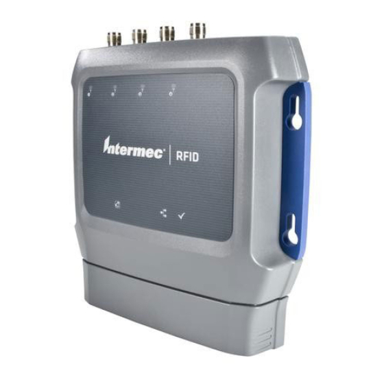
Chapter 1 — Getting Started Overview of the IF2 The IF2 Network Reader is an RFID reader that provides connectivity between tag data and an enterprise system. IF2 Network Reader Note: The IF2 does not ship with RFID antennas. For more information on these accessories, contact your Intermec sales representative. -
Page 13: Understanding The Leds
Chapter 1 — Getting Started Understanding the LEDs The IF2 has six LEDs that indicate the status of the reader during operation. Use the next table to identify the LED icons on the front panel of the IF2. IF2 LED Descriptions... -
Page 14: About The Intermec Ready-To-Work Indicator
About the Intermec Ready-to-Work Indicator The blue Ready-to-Work indicator shows when an application is communicating with the Basic Reader Interface (BRI) server or LLRP client on the IF2. The next table explains the different states of the Ready-to-Work indicator. Ready-to-Work Indicator Status Descriptions... - Page 15 IF2 Port Descriptions Port Description GPIO General purpose input/output (GPIO) port that connects the IF2 to industrial controls such as relays or indicators. For more information on the IF2 GPIO interfaces, see “About the GPIO Interfaces” on page 74. DC power Connects the reader to a 12 volt DC power source.
-
Page 16: Understanding The Top Panel Ports
Chapter 1 — Getting Started Understanding the Top Panel Ports The IF2 top panel ports consist of four antenna ports, a reset switch, and a USB service port. USB service port Reset switch Antenna port (4 places) IF2 Top Panel Ports The IF2 RFID antenna ports uses Reverse TNC connectors. -
Page 17: Communicating With The If2
DHCP server. Therefore, the IF2 will work out of the box if you connect it to your network and use a DHCP server to assign it an IP address. In this case, you configure the IF2 using the web browser interface from a desktop PC. For help, see “Using the Web... - Page 18 Chapter 1 — Getting Started To assign an initial IP address 1 Open a serial connection to the IF2. For help, see “Opening a Serial or USB Connection to the IF2” on page 54. 2 Type config and press Enter, and then type config again in the Password field and press Enter.
- Page 19 8 Press Q to close the Initial Configuration screen. 9 Disconnect the null-modem cable from the IF2. The IF2 is now ready to be connected to your network. See “Connecting the IF2 to Your Network” on page 15. IF2 Network Reader User’s Manual...
-
Page 20: Using The Web Browser Interface
When using the web browser interface, remember that your session automatically terminates if you do not use it for 15 minutes. Note: If you access the Internet using a proxy server, add the IF2 IP address to your Exceptions list. The Exceptions list contains the addresses that you do not want to use with a proxy server. - Page 21 4 If necessary, enter a user name and password. The default user name is and the default password is . You can intermec intermec define the user name and password. For help, see “Setting Up Logins” on page IF2 Network Reader User’s Manual...
-
Page 22: Saving Configuration Changes
For help with configuring RFID reader settings, see “Configuring BRI Settings” on page 38. For more information on other methods for managing the IF2, see “Managing the IF2” on page 50. Saving Configuration Changes After you make configuration changes, click Activate Changes in the browser window to save your changes and immediately make the changes active. -
Page 23: Installing The If2
3 Click Activate Changes to save your changes and immediately make them active. The Help text is disabled. Installing the IF2 This section explains how to mount the IF2 to a wall using the Network Reader Drilling Template Instructions that comes in the box with the IF2. - Page 24 3 Mount the IF2 using your parts and screws. Mounting screw (4 places) Note: The IF2 is certified to an IP53 environmental rating only when mounted as shown. The next table includes environmental requirements for the IF2. Choose a location that meets these requirements.
-
Page 25: Connecting The If2 To Your Network
Chapter 1 — Getting Started Connecting the IF2 to Your Network After you place the IF2 in its mounting location, you can connect it to your network. To connect the IF2 to your network 1 Install the IF2 in its mounting location. For help, see “Mount the... -
Page 26: Setting The Date And Time
Chapter 1 — Getting Started Setting the Date and Time After you have installed the IF2, you can set the date and time via the web browser interface. To set the date and time 1 Connect to the IF2 via the web browser interface. For help, see “Using the Web Browser Interface”... -
Page 27: Using The If2 Securely
Chapter 1 — Getting Started Using the IF2 Securely To help protect the integrity and security of your data, the IF2 supports a variety of secure access methods: • You can use a secure web browser session (HTTPS) to access the IF2. - Page 28 Chapter 1 — Getting Started IF2 Network Reader User’s Manual...
-
Page 29: Configuring Network Settings
Configuring Network Settings This chapter describes how to configure network settings for the IF2 and includes these topics: • Configuring Settings for Your Network • Configuring Security • Managing Certificates This chapter assumes that you are familiar with your network, networking terms, and the type of security implemented by your network. -
Page 30: Configuring Settings For Your Network
From a device management standpoint, there are several other methods you can use to configure network settings, including Intermec SmartSystems and the Device Configuration web service. For more information on using these methods to configure the IF2, “Managing, Troubleshooting, and Upgrading the see Chapter 4, IF2.”... - Page 31 2 Configure the Ethernet settings. For help, see the next table. Note: Different settings appear in this screen depending on the current DHCP mode for the IF2. If you need to configure other network settings such as DNS addresses and suffixes or a SYSLOG destination, see “Configuring Common Network Settings”...
- Page 32 Parameter Description Enable DHCP Check this check box if you want the IF2 to get its IP address from a DHCP server. If this check box is not checked, you need to specify the IP address, subnet mask, and IP router for your network.
-
Page 33: Configuring Common Network Settings
1 In the menu, click Network Configuration > Common. The Common screen appears. 2 Configure settings. For help, see the next table. 3 Click Activate Changes to save your changes and immediately make them active. IF2 Network Reader User’s Manual... -
Page 34: Configuring Security
DHCP server. If the server supports it, this field is used for dynamic DNS updates. DNS Server 1 IP address of a domain name server that the IF2 uses to resolve DNS names. DNS Server 2 IP address of a second domain name server that the IF2 uses to resolve DNS names. -
Page 35: Controlling Access Services
Securely” on page 17. Controlling Access Services Access services are the different ways that users can access and configure the IF2. You can control how developers access the IF2 by enabling or disabling these services: • Web browser interface (secure and non-secure) •... -
Page 36: Setting Up Logins
On the IF2, you need to enable RADIUS for login authorization. When you attempt to log in to the IF2, you must enter a user name and password. This login is sent to the RADIUS server, which compares the login to its list of authorized logins. If a match is found, you can log in to the IF2 with read/write privileges. -
Page 37: Configuring The If2 To Use A Password Server
29. Configuring the IF2 to Use a Password Server If you use a password server to manage users who log in to this IF2, you need to tell the IF2 how to communicate with the password server and then you need to configure the password server. - Page 38 RADIUS Server Information Descriptions Type Description Enable RADIUS Enables RADIUS authentication for this IF2. Primary Radius IP address or DNS name of the RADIUS server. If this Server field is blank, the RADIUS client does not use this entry.
-
Page 39: Changing The Default Login
Password Parameter Descriptions Parameter Description Username Enter the user name you need to use to log in to this IF2. The user name can be from 1 to 32 characters long. You must always specify a user name. Default is intermec Password Enter the password you need to use to log in to this IF2. -
Page 40: Disabling Access Via The Serial Port
Password Parameter Descriptions (continued) Parameter Description Read-only Enter the password you need to use to log in to this IF2. Password This password gives the user read-only access to the IF2. This user can view the configuration and execute diagnostics but cannot perform any tasks that affect IF2 operation, such as changing configuration options or upgrading firmware. -
Page 41: Managing Certificates
You can use a third-party certificate authority to issue unique client certificates and a root certificate. Note: To install or uninstall certificates, you need to access the IF2 via a secure web browser. For help, see “Using the Web Browser Interface”... -
Page 42: Installing And Uninstalling Certificates
Note: If you are not using a secure web browser, you will be prompted to log in again. Click A secure session is available and log in to the IF2. If a Security Alert dialog box appears, click Yes to proceed. Repeat Steps 1 and 2. - Page 43 4 (Server Certificate only) In the Enter the associated passphrase for this certificate field, carefully enter the passphrase for the certificate. 5 Click Import Certificate. If a Security Alert dialog box appears, click Yes to proceed. IF2 Network Reader User’s Manual...
- Page 44 Chapter 2 — Configuring Network Settings IF2 Network Reader User’s Manual...
-
Page 45: Developing And Using Rfid Applications
Developing and Using RFID Applications This chapter explains how you can develop and test RFID applications for the IF2 and includes these topics: • RFID Applications and the IF2 • Creating RFID Applications for the IF2 • Modifying IF4 Applications for Use With the IF2 •... -
Page 46: Rfid Applications And The If2
Reference Guide. The application you develop resides on a remote server which communicates with the IF2. In this case, all processing is performed by the server. Using the RFID Resource Kit The Intermec Developer Library RFID Resource Kit includes Java and C# tools you can use to develop applications that enable control of the reader and data management. -
Page 47: Creating Rfid Applications For The If2
Creating RFID Applications for the IF2 An RFID application can communicate directly with the IF2 BRI Server using the BRI protocol, or it can communicate with the IF2 using the Low-Level-Reader Protocol (LLRP). Intermec recommends that you write and test your application on a development workstation (your desktop PC). -
Page 48: About Rfid Services
Chapter 3 — Developing and Using RFID Applications • The IF2 is no longer guaranteed to be the only RFID module resource. The serial connection is one of eight possible connections. For more information on BRI, see the Basic Reader Interface Programmer’s Reference... -
Page 49: About Bri Attribute Settings
• ISO6B/G1 • ISO6B/G2 This setting is equivalent to the TAGTYPE BRI attribute. Read Tries Sets the maximum number of times the read algorithm is executed before a response is returned to a Read command. IF2 Network Reader User’s Manual... -
Page 50: Write Tries
Enables or disables a NOTAG message, which is sent when no tags are found during execution of a Read, Write, or Lock command. Check the check box to enable the message. This setting is equivalent to the NOTAGRPT BRI attribute, and is enabled by default. IF2 Network Reader User’s Manual... -
Page 51: Report Timeout
Chapter 3 — Developing and Using RFID Applications Report Timeout Sets the timeout (in ms) for delays in tag reporting when the IF2 is in continuous read mode. Range is 0 (default) to 65534. Timeout Configuration Mode Enables a timeout mode. Instead of specifying the number of antenna or ID tries, you specify an antenna or ID timeout value. -
Page 52: Initial Q
This setting is equivalent to the IDTRIES BRI attribute. Antenna Tries Sets the maximum number of ID Tries that the reader executes per antenna. Valid range is 1 to 254 (default is 3). This setting is equivalent to the ANTTRIES BRI attribute. IF2 Network Reader User’s Manual... -
Page 53: Epcc1G2 Advance Medium Access Mode
The IF2 BRI server handles communication between your application and the RFID module. When your application is communicating with the BRI server, the blue Intermec Ready-To-Work Indicator on the IF2 front panel turns on and stays on. For more information, see “About... -
Page 54: Viewing The Bri Server Log
BRI TCP Port Specifies the TCP port used for incoming connections to the BRI server. This port must be unique for all TCP services running on the IF2. Valid range is 2189 to 65535. Default is 2189. Enable Logging Enables/disables logging of BRI server events. - Page 55 Message type of the event, generally indicating which system sent the message: 1 = Command received by BRI server 2 = Response sent by BRI server 3 = BRI server connection message Message Text of the message, including responses. IF2 Network Reader User’s Manual...
-
Page 56: Configuring Llrp Settings
Chapter 3 — Developing and Using RFID Applications Configuring LLRP Settings The IF2 supports version 1.0.1 of the EPCglobal Low-Level Reader Protocol (LLRP), which establishes a specific interface method between a reader and its corresponding client. Follow the next procedure to configure LLRP settings. - Page 57 LLRP server on port 5085. Unsecure Server Enable Check this check box to allow connections to the unsecure LLRP server on port 5084. Download Intermec Click the link to download the Intermec extension Extension Definitions definitions xml file. Reader-Initiated...
- Page 58 Chapter 3 — Developing and Using RFID Applications IF2 Network Reader User’s Manual...
-
Page 59: Managing, Troubleshooting, And Upgrading The If2
Managing, Troubleshooting, and Upgrading the IF2 This chapter includes information on managing the IF2 and includes these topics: • Managing the IF2 • Using the Device Configuration Web Service • Using SmartSystems Foundation • Opening a Serial or USB Connection to the IF2 •... -
Page 60: Managing The If2
Chapter 4 — Managing, Troubleshooting, and Upgrading the IF2 Managing the IF2 There are several methods you can use to manage the IF2. You can use: • a web browser. For help, see “Using the Web Browser Interface” on page 10. - Page 61 Chapter 4 — Managing, Troubleshooting, and Upgrading the IF2 To enable the web service and download the WSDL document 1 From the menu, click Network Configuration > Device Management. The Device Management screen appears. By default, Device Configuration web services are enabled for either secure or insecure connections.
-
Page 62: Using Smartsystems Foundation
DeviceConfiguration.wsdl. The document opens in the browser window. Using SmartSystems Foundation The IF2 ships with a SmartSystems™ client, which means you can manage it from a central host PC using Intermec’s SmartSystems Foundation. The SmartSystems Console displays all discovered SmartSystems devices in your network. - Page 63 After you specify the server address, SmartSystems will discover the IF2 during the next broadcast interval. To disable SmartSystems access to the IF2, uncheck the Enable SmartSystems Access check box. 3 Click Activate Changes to save your settings and immediately make them active.
-
Page 64: Configuring The If2 With Intermec Settings
Help > Online Manual. Opening a Serial or USB Connection to the IF2 You can connect the IF2 to your desktop PC via the serial or USB port to perform these tasks: Assign the IF2 an initial IP address. -
Page 65: Opening A Serial Connection To The If2
ActiveSync to make the serial port available. To connect to the IF2 via the serial port 1 Connect the null-modem cable from the serial port on the IF2 to a serial port on your PC. 2 Start the communications program and configure the serial port... -
Page 66: Opening A Usb Connection To The If2
62. • You can open a BRI session. Opening a USB Connection to the IF2 If you are connecting the IF2 using a USB connection, you need: • a USB cable. • to create a folder with a gserial.inf and a usbser.sys file. - Page 67 9 Copy the usb.sys file to the folder you created in Step 1. 10 Connect the IF2 to your PC using a USB cable. The Found New Hardware Wizard appears. 11 Select Install from a list or specific location (Advanced), and click Next.
-
Page 68: Maintaining The If2
Intermec Product Support. Viewing the System Log The System Log screen shows events that have been logged by the IF2. To view the System Log screen 1 From the menu, click Maintenance > System Log. The System Log screen appears. -
Page 69: Viewing The About Screen
Device information: IF2 firmware version, hardware configuration string, and serial number. • System information: Available memory, number of running processes, and amount of time the IF2 has been running. • RFID Module firmware: Firmware version installed. • Network interface information. -
Page 70: Using The Leds To Locate The If2
Chapter 4 — Managing, Troubleshooting, and Upgrading the IF2 Using the LEDs to Locate the IF2 You can use the LEDs to help locate a specific IF2 in your location. To locate an IF2 • In the About This IF2 RFID Reader screen, click Find This Device. -
Page 71: Restoring Default Settings Using The Web Browser
Chapter 4 — Managing, Troubleshooting, and Upgrading the IF2 Restoring Default Settings Using the Web Browser If you are having problems with the IF2, you can use the web browser interface to restore the default settings to the IF2. To restore defaults using the web browser 1 From the menu, click Maintenance >... -
Page 72: Restoring Default Settings Using The Reset Switch
Chapter 4 — Managing, Troubleshooting, and Upgrading the IF2 Restoring Default Settings Using the Reset Switch If you are having problems with the IF2, you can press the reset switch to restore the default settings to the IF2. To restore defaults via a serial connection 1 Make sure the IF2 is powered on. -
Page 73: Rebooting The If2
To reboot the IF2 1 From the menu, click Maintenance > Reboot. The Reboot screen appears. 2 Click Reboot to reboot the IF2. You need to log in again after the IF2 reboots. IF2 Network Reader User’s Manual... -
Page 74: Troubleshooting The If2
RFID module, you can use a communications program to verify that the RFID module is working properly. You need to know the IF2 IP address to connect directly to the RFID module. To verify that the RFID reader is reading tags, you need a known good RFID antenna and at least one good RFID tag. - Page 75 Chapter 4 — Managing, Troubleshooting, and Upgrading the IF2 To connect directly to the IF2 RFID module and verify operation 1 Make sure the RFID antenna is connected properly to the IF2. 2 Apply power to the IF2. 3 Use a communications program (such as HyperTerminal) to open...
-
Page 76: Problems With Connectivity
Verify that you have the correct IP address for the IF2. using a web browser. If you access the Internet through a proxy server, be sure you have added the IP address of the IF2 to the Exceptions list. You cannot load a security You must use a secure web browser connection to load certificate. -
Page 77: Calling Intermec Product Support
Chapter 4 — Managing, Troubleshooting, and Upgrading the IF2 Calling Intermec Product Support You may need to call Intermec Product Support if you have problems operating the IF2. Before calling, be sure you can answer the following questions: • What kind of network are you using? •... -
Page 78: Upgrading Firmware
2 Run the Upgrade Package utility to configure the firmware upgrade file. For help, see the next section. 3 Install and run the firmware upgrade file on the IF2. For help, see “Installing the Firmware Upgrade” on page 70. IF2 Network Reader User’s Manual... -
Page 79: Configuring The Firmware Upgrade
1 Double-click the Upgrade Package utility to run it. The opening screen appears. 2 Click Next. 3 If you are going to upgrade the IF2 via the web browser interface, deselect the SmartSystems Upgrade Bundle button and click Next. The bundle install location screen appears. -
Page 80: Installing The Firmware Upgrade
Chapter 4 — Managing, Troubleshooting, and Upgrading the IF2 Installing the Firmware Upgrade This section describes the different methods of how to install and run the IF2 firmware upgrade. Upgrading From the Web Browser Interface You can use the web browser interface to upgrade the firmware on the IF2. -
Page 81: Upgrading With Smartsystems Foundation
The SmartSystems server shows the IF2 as being offline until the reader reboots and reconnects to the system. Do not cycle power to the IF2 during the upgrade. If power is lost during the upgrade, the IF2 may require factory repair. - Page 82 Chapter 4 — Managing, Troubleshooting, and Upgrading the IF2 IF2 Network Reader User’s Manual...
-
Page 83: Using The If2 Gpio Interfaces
Using the IF2 GPIO Interfaces This chapter explains how to access the IF2 general purpose input/output (GPIO) interfaces and how to connect industrial controls such as motion sensors or indicator lamps to the IF2. This chapter includes the following topics: •... -
Page 84: About The Gpio Interfaces
GPIO interfaces, which can then trigger IF2 operations. Each interface is electrically isolated from the IF2 and designed for low voltage DC loads. The IF2 can also supply 12 VDC at 0.5 A to external devices. How the inputs and outputs are used depends on the RFID application software being used in the system. -
Page 85: Using The Input Interfaces
If the external control device is a switch, you can connect one side of the switch to an IF2 +Input pin, and the other side of the switch to one of the +12 VDC sources. Ground the corresponding -Input pin as shown in the next illustration. -
Page 86: Isolated Input Interface
IF2 and the input device. In this situation, the IF2 provides power to the pull-up resistor for the open collector. Connect the +Input pin to the +12 VDC source as shown in the next illustration. -
Page 87: Using The Output Interfaces
Each IF2 output interface is optically isolated from the IF2, polarized, and rated for 5 to 48 VDC at 0.25 A. All IF2 outputs include internal thermal fuses that trip if the load exceeds 0.25 A, and the fuses are self-recovering once the excessive load is removed. -
Page 88: Switching The High Side Using If2 Power
Chapter 5 — Using the IF2 GPIO Interfaces These methods are shown in the next examples. Switching the High Side Using IF2 Power In this example, an external indicator lamp (0.25 A maximum current) is connected to the -Output and Ground pins, and the corresponding +Output pin is connected to the +12 VDC source. -
Page 89: Switching The High Side Using External Power
Switching the High Side With External Power Driving a DC Relay to Control an AC Load While the IF2 outputs are designed to switch DC loads, they can drive relays that control AC loads. The next illustration shows how to connect such a system to an IF2 output. -
Page 90: Using The Power Interface
Using the Power Interface The IF2 GPIO interface provides 12 VDC at 0.5 A for powering external inputs and loads, eliminating the need for an external DC supply and simplifying the system installation. -
Page 91: Specifications
Specifications This appendix includes physical and electrical specifications for the IF2 and information about the port pin assignments. -
Page 92: If2 Specifications
5% to 95% non-condensing (non-condensing) Ethernet interfaces 10BaseT/100BaseTx (twisted-pair) with 802.3at High Power Over Ethernet (POE) Ethernet compatibility Ethernet frame types and Ethernet addressing Ethernet data rate 10 Mbps/100 Mbps Serial port maximum 115,200 bps data rate IF2 Network Reader User’s Manual... -
Page 93: Rfid Specifications
> 200 tags per second Transmitter type 90% amplitude modulation index Frequency stability <±100 ppm from -25°C to +55°C (-13°F to 131°F) Number of antennas Up to 4, electronically switched Antenna port isolation 22 dB Antenna connectors Reverse TNC IF2 Network Reader User’s Manual... -
Page 94: Port Pin Assignments
High (10-48V) Ground +Output 4 High (10-48V) +Input 1 High (10-48V) +Input 2 High (10-48V) +Input 3 High (10-48V) +Input 4 High (10-48V) 12VDC -Output 1 Low-RTN 12VDC -Output 2 Low-RTN 12VDC -Output 3 Low-RTN IF2 Network Reader User’s Manual... -
Page 95: Serial Ports (Com1)
Active Polarity 12VDC -Output 4 Low-RTN Serial Ports (COM1) Pin 1 Pin 9 Serial Port Pin Assignments Description Active Polarity Receive data (RXD) Transmit data (TXD) Signal ground Request to send (RTS) Clear to send (CTS) IF2 Network Reader User’s Manual... -
Page 96: Ethernet Port
Ethernet Port Pin Assignments Description Ethernet TX+/Spare POE return Ethernet TX-/Spare POE return Ethernet RX+/Spare POE 48 VDC Not used/POE 48 VDC Not used/POE 48 VDC Ethernet RX-/Spare POE 48 VDC Not used/POE return Not used/POE return IF2 Network Reader User’s Manual... -
Page 97: Index
Index... - Page 98 IF2 certificates with Intermec RFID Resource described installing and uninstalling Device Configuration web service viewing Common Internet File System DHCP settings, configuring shares, enabling diagnostics configuring the IF2 BRI server event log, viewing IF2 Network Reader User’s Manual...
- Page 99 Index events log, viewing firmware, upgrading installing upgrade file on IF2 server IP address, setting overview settings, configuring upgrade file, configuring suffixes, setting web browser interface DRM equivalent Forced Client Termination front panel ports accessing edgeware described updates, locating electrical specifications...
- Page 100 IF2 INITIALQ equivalent Maintenance menu INITTRIES equivalent events log, viewing input interface locating the IF2 isolated using LEDs to locate the IF2 open collector managing the IF2 powered defaults, restoring signal descriptions developer access, controlling installing Device Configuration web...
- Page 101 Power LED password server, using with IF2 Power Over Ethernet problems with IF2, solving supported methods Product Support, calling Intermec Select Tries setting SELTRIES equivalent proxy server, using to access...
- Page 102 Wired LAN LED SNTP client settings Write Tries setting Time screen WRTRIES equivalent Timeout Configuration mode, WSDL document, downloading enabling www.intermec.com, accessing from TIMEOUTMODE equivalent IF2 web browser interface top panel ports, described and illustrated IF2 Network Reader User’s Manual...
- Page 104 Worldwide Headquarters 6001 36th Avenue West Everett, Washington 98203 U.S.A. tel 425.348.2600 fax 425.355.9551 www.intermec.com © 2011 Intermec Technologies Corporation. All rights reserved. IF2 Network Reader User’s Manual *935-040-001* P/N 935-040-001...
Need help?
Do you have a question about the IF2 and is the answer not in the manual?
Questions and answers