Table of Contents
Advertisement
Advertisement
Table of Contents

Related Manuals for Intermec 1009FF01


Summary of Contents for Intermec 1009FF01
- Page 1 IF 2 Network Reader Model 1009FF01 User Manual...
- Page 2 LGPL v2.1 (www.gnu.org/licenses/lgpl-2.1.html). You may obtain the complete Corresponding Source code from Intermec (www.intermec.com) for a period of three years after Intermec's last shipment of this product. This offer is valid to anyone in receipt of this information.
- Page 3 Document Change Record This page records changes to this document. The document was originally released as Revision 001. Version Number Date Description of Change 3/2014 Revised to support the IF2 with expanded memory option. IF2 Network Reader User Manual...
- Page 4 IF2 Network Reader User Manual...
-
Page 5: Table Of Contents
Contents Contents Before You Begin..............xi Safety Information . - Page 6 Contents Configure Security ............. . . 26 Control Access Services .
- Page 7 Contents Antenna Sequence: First through Eighth......45 Configure the BRI Server ..........45 View the BRI Server Log .
- Page 8 Call Intermec Product Support........
- Page 9 Specifications ............91 IF2 Specifications .
- Page 10 IF2 Network Reader User Manual...
-
Page 11: Before You Begin
Safety Information Your safety is extremely important. Read and follow all warnings and cautions in this document before handling and operating Intermec equipment. You can be seriously injured, and equipment and data can be damaged if you do not follow the safety warnings and cautions. -
Page 12: Global Services And Support
Before You Begin Global Services and Support Warranty Information To understand the warranty for your Intermec product, visit the Intermec web site at www.intermec.com and click Support > Returns and Repairs > Warranty. Disclaimer of warranties: The sample code included in this document is presented for reference only. -
Page 13: Who Should Read This Manual
(as PDF files) that you can download for free. To download documents 1 Visit the Intermec web site at www.intermec.com. 2 Click Products tab. 3 Using the Products menu, navigate to your product page. For example, to find the IF2 RFID reader, click RFID > Network Readers >... - Page 14 IF2 Network Reader User Manual...
-
Page 15: About The Rfid Reader
About the RFID Reader This chapter introduces the IF2 Network Reader, explains the ports and LEDs, and explains how the reader fits into your network. It contains these topics: • About the IF2 • How to Communicate with the IF2 •... -
Page 16: About The If2
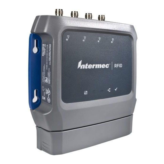
Chapter 1 — About the RFID Reader About the IF2 The IF2 Network Reader is an RFID reader that provides connectivity between tag data and an enterprise system. IF2 Network Reader Note: The IF2 does not ship with RFID antennas. For more information on these accessories, contact your sales representative. -
Page 17: About The Leds
Use the next table to identify the LED icons on the front panel of the IF2. IF2 LED Descriptions Icon Name Description • Intermec On when an application is communicating Ready-to-Work™ with the IF2 BRI server or an LLRP client has indicator connected. •... - Page 18 Chapter 1 — About the RFID Reader IF2 LED Descriptions (continued) Icon Name Description • Power Over Green if Power Over Ethernet (POE) is Ethernet enabled. • Red if a fault condition is detected. For example, if the power converter for POE does not provide enough power to the IF2, the POE LED stays red indicating a fault condition.
-
Page 19: About The Ready-To-Work Indicator
Chapter 1 — About the RFID Reader About the Ready-to-Work Indicator The blue Ready-to-Work indicator shows when an application is communicating with the Basic Reader Interface (BRI) server or LLRP client on the IF2. The next table explains the different states of the Ready-to-Work indicator. - Page 20 Chapter 1 — About the RFID Reader IF2 Port Descriptions Port Description GPIO General purpose input/output (GPIO) port that connects the IF2 to industrial controls such as relays or indicators. For more information on the IF2 GPIO interfaces, see “About the GPIO Interfaces” on page 84. DC power Connects the reader to a 12 volt DC power source.
-
Page 21: About The Top Panel Ports
Chapter 1 — About the RFID Reader About the Top Panel Ports The IF2 top panel ports consist of four antenna ports, a reset switch, and a USB service port. USB service port Reset switch Antenna port (4 places) IF2 Top Panel Ports The IF2 RFID antenna ports uses Reverse TNC connectors. -
Page 22: How To Communicate With The If2
Chapter 1 — About the RFID Reader How to Communicate with the IF2 By default, the IF2 is configured to be a DHCP client and accepts offers from any DHCP server. Therefore, the IF2 will work out of the box if you connect it to your network and use a DHCP server to assign it an IP address. - Page 23 Chapter 1 — About the RFID Reader To assign an initial IP address 1 Open a serial connection to the IF2. For help, see “Open a Serial or USB Connection to the IF2” on page 64. 2 Type config and press Enter, and then type config again in the Password field and press Enter.
- Page 24 Chapter 1 — About the RFID Reader 4 To set the IP address, press 1 and enter the static IP address in the entry field. 5 Press Enter. The static IP address is set. If you do not need to set the subnet mask or IP router values, you can now continue to configure the IF2 through the web browser interface.
-
Page 25: Use The Web Browser Interface
Chapter 1 — About the RFID Reader Use the Web Browser Interface After the IF2 is assigned an IP address, configure the IF2 using the web browser interface. To use the web browser interface, the IF2 must be connected to your wired network. - Page 26 IF2 Secure Login Screen 4 If necessary, enter a user name and password. The default user name is and the default password is . You can intermec intermec define the user name and password. For help, see “Set Up Logins” on page...
-
Page 27: Save Configuration Changes
Chapter 1 — About the RFID Reader 5 Click Login (or Secure Login in the secure login screen). The Ethernet screen appears and your web browser session is established. For help with configuring network settings, see “Configure the Settings for Your Network” on page 22. For help with configuring RFID reader settings, see “Configure BRI Settings”... - Page 28 Chapter 1 — About the RFID Reader To disable help text 1 In the web browser interface, click Help in the upper right corner of the screen. The Help screen appears. 2 Clear the Enable Help check box. 3 Click Activate Changes to save your changes and immediately make them active.
-
Page 29: Install The If2
Network Reader Drilling Template Instructions that comes in the box with the IF2. The IF2 should be professionally installed. For more information, contact your local Intermec representative. To install the IF2 1 Choose a mounting location. 2 Use the IF2 Network Reader Drilling Template Instructions to drill holes in the mounting location. -
Page 30: Connect The If2 To Your Network
Chapter 1 — About the RFID Reader The next table includes environmental requirements for the IF2. Choose a location that meets these requirements. IF2 Environmental Requirements Type Minimum Maximum -20 ºC (-4 ºF) 55 ºC (13 1ºF) Operating temperature -30 ºC (-22 ºF) 70 ºC (158 ºF) Storage temperature Humidity (non-condensing) - Page 31 Chapter 1 — About the RFID Reader The IF2 is now ready to communicate with your network. Once the IF2 has been assigned an IP address (either manually or from your DHCP server), you can use the web browser interface to complete configuration.
-
Page 32: Set The Date And Time
Chapter 1 — About the RFID Reader Set the Date and Time After you have installed the IF2, you can set the date and time via the web browser interface. To set the date and time 1 Connect to the IF2 via the web browser interface. For help, see “Use the Web Browser Interface”... -
Page 33: How To Use The If2 Securely
Chapter 1 — About the RFID Reader How to Use the IF2 Securely To help protect the integrity and security of your data, the IF2 supports a variety of secure access methods: • You can use a secure web browser session (HTTPS) to access the IF2. - Page 34 Chapter 1 — About the RFID Reader IF2 Network Reader User Manual...
-
Page 35: Configure Network Settings
Configure Network Settings This chapter describes how to configure network settings for the IF2 and includes these topics: • Configure the Settings for Your Network • Configure Security • Manage Certificates This chapter assumes that you are familiar with your network, networking terms, and the type of security implemented by your network. -
Page 36: Configure The Settings For Your Network
Chapter 2 — Configure Network Settings Configure the Settings for Your Network You use the web browser interface to configure network settings. For more information on using the web browser, see “Use the Web Browser Interface” on page 11. This chapter explains how to use the web browser interface to configure settings for: •... - Page 37 Chapter 2 — Configure Network Settings To configure Ethernet settings 1 From the menu, click Network Configuration or Ethernet in the left pane. The Ethernet screen appears. If DHCP is enabled, you see this screen: If DHCP is disabled, the current values for IP address, subnet mask, and router appear in entry fields: 2 Configure the Ethernet settings.
- Page 38 Chapter 2 — Configure Network Settings 3 Click Activate Changes to save your changes and immediately make them active. Ethernet Settings Descriptions Parameter Description Enable DHCP Check this check box if you want the IF2 to get its IP address from a DHCP server.
-
Page 39: Configure Common Network Settings
Chapter 2 — Configure Network Settings Configure Common Network Settings Common network settings are configuration items that apply to the IF2 network interface. This section explains how to use the web browser interface to configure these common network settings: • Hostname Domain Name Server (DNS) addresses and suffixes •... -
Page 40: Configure Security
Chapter 2 — Configure Network Settings Common Network Settings Descriptions Parameter Description Hostname Name for this IF2. The default is “IF2<serial number of the IF2>”. The hostname can be either a simple hostname, or a qualified domain name (FQDN). If this IF2 obtains its IP address via DHCP, this parameter is sent to the DHCP server. -
Page 41: Control Access Services
Chapter 2 — Configure Network Settings • disable serial port access to the IF2. For help, see “Disable Access Through the Serial Port” on page 32. For general information on securely using the IF2, see “How to Use the IF2 Securely” on page 19. Control Access Services Access services are the different ways that users can access and configure the IF2. -
Page 42: Set Up Logins
Chapter 2 — Configure Network Settings Access Services Descriptions Service Description Enable Web Server Enables access to the IF2 via the web browser interface. Select Enable Web Server (Insecure) to allow users to log in using either a nonsecure (HTTP via port 80) or secure (HTTPS via port 443) web interface. -
Page 43: Configure The If2 To Use A Password Server
Chapter 2 — Configure Network Settings • If you do not want to use a password server, you should change the default login user name and password, and create a read-only password. For help, see “Change the Default Login” on page 31. Configure the IF2 to Use a Password Server If you use a password server to manage users who log in to this IF2, you need to tell the IF2 how to communicate with the password server... - Page 44 Chapter 2 — Configure Network Settings 2 Check the Enable RADIUS check box. A list of RADIUS configuration items appears. 3 Configure the settings. For help, see the next table. 4 Click Activate Changes. 5 Configure the password server database. For help, see the documentation that came with your server.
-
Page 45: Change The Default Login
Option. Change the Default Login If you are not using a password server to authorize user logins, Intermec recommends that you change the default user name and password and create a read-only password. To set up logins 1 From the main menu, click Security > Passwords. The Passwords screen appears. -
Page 46: Disable Access Through The Serial Port
This password gives you read and write access to the IF2 configuration. The password can be from 8 to 32 characters long. You must always specify a password. Default is intermec. Read-only Enter the password you need to use to log in to this IF2. -
Page 47: Manage Certificates
Chapter 2 — Configure Network Settings To disable serial port access 1 From the menu, click Security > Passwords. The Passwords screen appears. 2 Clear the Enable Serial Configuration check box. 3 Click Activate Changes to save your changes and immediately make them active. -
Page 48: View Certificates
Chapter 2 — Configure Network Settings View Certificates You can use the web browser interface to view the certificates loaded on the IF2. To view certificates • From the menu, click Security > Certificate Details. The Certificate Details screen appears. The Server Certificate table lists the server certificate that is installed, and the CA Certificate table lists the trusted CA certificate that is installed. -
Page 49: Install And Uninstall Certificates
Chapter 2 — Configure Network Settings Install and Uninstall Certificates Once you have determined that you need to install or uninstall a certificate, use this procedure. Note: If you follow the procedure to uninstall all certificates, you will lose the unique server certificate and the trusted CA certificate. You will need to contact your local representative to purchase new certificates. - Page 50 Chapter 2 — Configure Network Settings 4 (Server Certificate only) In the Enter the associated passphrase for this certificate field, carefully enter the passphrase for the certificate. 5 Click Import Certificate. If a Security Alert dialog box appears, click Yes to proceed. IF2 Network Reader User Manual...
-
Page 51: Develop And Use Rfid Applications
Develop and Use RFID Applications This chapter explains how you can develop and test RFID applications for the IF2 and IF2 with expanded memory option and includes these topics: • About the IF2 Configurations • RFID Applications and the IF2 •... -
Page 52: About The If2 Configurations
Chapter 3 — Develop and Use RFID Applications About the IF2 Configurations The IF2 comes in a standard configuration with no internal memory, or an expanded memory option. • For the IF2, the applications you develop resides on a remote server which communicates with the reader, and all information is processed through the server. -
Page 53: Use The Rfid Resource Kit
C# tools you can use to develop applications that enable control of the reader and data management. The resource kit is available as part of the Intermec Developer Library (IDL). To learn more about the RFID Resource Kit, go to www.intermec.com... -
Page 54: Configure Bri Settings
Chapter 3 — Develop and Use RFID Applications Configure BRI Settings This section explains how to configure BRI settings that control reader operation and communication with your application. • To configure BRI attribute settings that control reader operation, such as read and write tries, tag types, or antenna settings, see the next section, “Changing BRI Attribute Settings.”... -
Page 55: About Bri Attribute Settings
Chapter 3 — Develop and Use RFID Applications About BRI Attribute Settings This section explains the BRI attribute settings that control how the reader operates. For more information, see the Basic Reader Interface Programmer’s Reference Manual. Tag Types Check the appropriate check boxes to enable RFID operations for these kinds of tags: •... -
Page 56: Field Separator
Chapter 3 — Develop and Use RFID Applications Field Separator Sets the character to be used for separating fields in tag data. Choose from space ( ), comma (,), colon (:), semicolon (;), tab, caret (^), or tilde (~). Default is space. This setting is equivalent to the FIELDSEP BRI attribute. -
Page 57: Select Tries
Chapter 3 — Develop and Use RFID Applications 2 Specify the value (in ms) for the antenna or ID timeout in the entry fields and then click Activate Changes. For more information on ID Timeout and Antenna Timeout, see those topics later in this section. Select Tries (Not supported by EPCglobal Class 1 Gen 2 tags) Sets the number of times a group select is attempted. -
Page 58: Schedule Option
Chapter 3 — Develop and Use RFID Applications Schedule Option Determines how antennas are switched during the inventory process. This attribute controls the behavior of the inventory scheduling parameters. This setting is equivalent to the SCHEDULOPT BRI attribute. ID Tries Sets the maximum number of times the reader executes the identify algorithm before a response is returned to a Read or Write command. -
Page 59: Antenna Field Strength 1 To 4
The IF2 BRI server handles communication between your application and the RFID module. When your application is communicating with the BRI server, the blue Intermec Ready-To-Work Indicator on the IF2 front panel turns on and stays on. For more information, see “About... -
Page 60: View The Bri Server Log
Chapter 3 — Develop and Use RFID Applications 2 Change BRI server settings as needed. For help, see the next table. 3 Click Activate Changes to save your changes and immediately make them active. BRI Server Parameter Descriptions Parameter Description Enable External Enables/disables external TCP connections to the BRI BRI Connections... - Page 61 Chapter 3 — Develop and Use RFID Applications 2 In the left navigation list, click RFID Services > BRI > BRI Log. The BRI Log screen appears with a list of BRI events. For more information on server events, see the next table, “BRI Event Descriptions.”...
-
Page 62: Configure Llrp Settings
Chapter 3 — Develop and Use RFID Applications Configure LLRP Settings The IF2 supports version 1.0.1 of the EPCglobal Low-Level Reader Protocol (LLRP), which establishes a specific interface method between a reader and its corresponding client. Follow the next procedure to configure LLRP settings. For information on LLRP, including standards, see http://www.epcglobalinc.org/standards/llrp. - Page 63 LLRP server on port 5085. Unsecure Server Enable Check this check box to allow connections to the unsecure LLRP server on port 5084. Download Intermec Click the link to download the Intermec extension Extension Definitions definitions xml file. Reader-Initiated...
- Page 64 Chapter 3 — Develop and Use RFID Applications IF2 Network Reader User Manual...
-
Page 65: Install Applications On The If2 With Expanded Memory Option
Install Applications on the IF2 with Expanded Memory Option This chapter explains how you can develop and install applications on the IF2 with Expanded Memory option. • Create a Configuration File • Auto-Start Applications at Boot Time • About .NET Support •... -
Page 66: Create A Configuration File
Chapter 4 — Install Applications on the IF2 with Expanded Memory Option Create a Configuration File When you package your application for installation on the IF2, you need to include a configuration file in the root directory of the archive. The file must be named “userapp.conf” and must include this syntax: AUTOSTART=true|false RUNAFTERINSTALL=true|false... -
Page 67: Auto-Start Applications At Boot Time
Chapter 4 — Install Applications on the IF2 with Expanded Memory Option Note: The IF2 executes applications from their installation directories, so the userapp.conf file does not need to include path information. Auto-Start Applications at Boot Time There are two ways to configure your application to auto-start when the IF2 boots: •... -
Page 68: Execute Java Applications
Java runtime executable installed in the IF2. If your application references third party Java libraries (such as components from the Intermec RFID Resource Kit), you must use the “-cp” option to specify the class path for the JVM to find the Java classes. -
Page 69: Java Support For Microsoft Sql Server And Sybase
Chapter 4 — Install Applications on the IF2 with Expanded Memory Option Java Support for Microsoft SQL Server and Sybase The IF2 jTDS driver (version 1.2) provides JDBC capabilities to Java applications running on the IF2. You need to include the location of JDBC drivers in the class path. -
Page 70: Manage Applications
Chapter 4 — Install Applications on the IF2 with Expanded Memory Option Manage Applications To maximize IF2 resources, you can start, stop, or uninstall IF2 edgeware applications or your installed applications from the web browser interface. You can also configure applications to auto-start at boot time. -
Page 71: About The Edgeware Applications
You use the web browser interface to install or upgrade IF2 edgeware applications, such as the SAP device controller. Note: Use only .bin files provided by Intermec. To install your own applications in .zip, .tar, .tar/bz2, or .tar/gz formats, see “Install... -
Page 72: About The Developer Tools
Chapter 4 — Install Applications on the IF2 with Expanded Memory Option About the Developer Tools Use the Developer Tools for basic testing of your RFID system. The Developer Tools support these features: • General purpose input/output (GPIO) testing. For help, see the next section. -
Page 73: Send Bri Commands And Running Scripts
Chapter 4 — Install Applications on the IF2 with Expanded Memory Option Send BRI Commands and Running Scripts You can send BRI commands to the IF2 or load and run a BRI script through the web browser interface. To send BRI commands 1 From the menu, click Edgeware Applications >... - Page 74 Chapter 4 — Install Applications on the IF2 with Expanded Memory Option 3 To save your JavaScript code to the IF2 work buffer, click Save As and enter a new file name in the entry field. Click OK. If you previously saved your JavaScript, click on the drop-down menu and select the file name to reload it in the JavaScript Code box.
-
Page 75: Manage, Troubleshoot, And Upgrade The If2
Manage the IF2 • Use the Device Configuration Web Service • Open a Serial or USB Connection to the IF2 • Maintain the IF2 • Troubleshoot the IF2 • Call Intermec Product Support • Access Web Pages • Upgrade Firmware... -
Page 76: Manage The If2
Chapter 5 — Manage, Troubleshoot, and Upgrade the IF2 Manage the IF2 There are two methods you can use to manage the IF2. You can use: • a web browser. For help, see “Use the Web Browser Interface” on page 11. This manual assumes you are using this method for all procedures. - Page 77 Chapter 5 — Manage, Troubleshoot, and Upgrade the IF2 To enable the web service and download the WSDL document 1 From the menu, click Network Configuration > Device Management. The Device Management screen appears. By default, Device Configuration web services are enabled for either secure or insecure connections.
-
Page 78: Open A Serial Or Usb Connection To The If2
Chapter 5 — Manage, Troubleshoot, and Upgrade the IF2 To download the device configuration WSDL document, click DeviceConfiguration.wsdl. The document opens in the browser window. Open a Serial or USB Connection to the IF2 You can connect the IF2 to your desktop PC via the serial or USB port to perform these tasks: •... -
Page 79: Open A Serial Connection To The If2
Chapter 5 — Manage, Troubleshoot, and Upgrade the IF2 Open a Serial Connection to the IF2 If you are opening a serial connection to the IF2, you need: • a null-modem cable (P/N 059167). • a communications program such as HyperTerminal. Note: If you have Microsoft ActiveSync running on your desktop PC, disable ActiveSync to make the serial port available. -
Page 80: Open A Usb Connection To The If2
Chapter 5 — Manage, Troubleshoot, and Upgrade the IF2 • You can restore default settings. For help, see “To restore defaults with a serial connection” on page 72. • You can open a BRI session. Open a USB Connection to the IF2 If you are connecting the IF2 using a USB connection, you need: •... - Page 81 Chapter 5 — Manage, Troubleshoot, and Upgrade the IF2 [GSerialAddReg] HKR,,DevLoader,,*ntkern HKR,,NTMPDriver,,usbser.sys HKR,,EnumPropPages32,,"MsPorts.dll,SerialPortPropPageProvider" [GSerialInstall.Services] AddService = usbser,0x0002,GSerialService [GSerialService] DisplayName = %GSERIAL_DISPLAY_NAME% ServiceType = 1 ; SERVICE_KERNEL_DRIVER StartType = 3 ; SERVICE_DEMAND_START ErrorControl = 1 ; SERVICE_ERROR_NORMAL ServiceBinary = %10%\System32\Drivers\usbser.sys LoadOrderGroup = Base [Strings] LINUX = "Linux"...
-
Page 82: Maintain The If2
The Maintenance menu lets you view IF2 parameters and statistics, including a list of logged events. You may need this information if you need to call Intermec Product Support. View the System Log The System Log screen shows events that have been logged by the IF2. -
Page 83: View The About Screen
Chapter 5 — Manage, Troubleshoot, and Upgrade the IF2 View the About Screen The About screen lists installed software versions, serial numbers, and other IF2-specific information. To view the About screen From the menu, click About. The About screen appears. This •... -
Page 84: Use The Leds To Locate The If2
Chapter 5 — Manage, Troubleshoot, and Upgrade the IF2 Use the LEDs to Locate the IF2 You can use the LEDs to help locate a specific IF2 in your location. To locate an IF2 • In the About This IF2 RFID Reader screen, click Find This Device. -
Page 85: Restore Default Settings With The Web Browser
Chapter 5 — Manage, Troubleshoot, and Upgrade the IF2 Restore Default Settings with the Web Browser If you are having problems with the IF2, you can use the web browser interface to restore the default settings to the IF2. To restore defaults with the web browser 1 From the menu, click Maintenance >... -
Page 86: Restore Default Settings With The Reset Switch
Chapter 5 — Manage, Troubleshoot, and Upgrade the IF2 Restore Default Settings with the Reset Switch If you are having problems with the IF2, you can press the reset switch to restore the default settings to the IF2. To restore defaults with the reset switch 1 Make sure the IF2 is powered on. -
Page 87: Reboot The If2
Chapter 5 — Manage, Troubleshoot, and Upgrade the IF2 Reboot the IF2 You can reboot the IF2 from the web browser interface as described in the next procedure. For example, you may need to reboot the IF2 to enable changes in an application. To reboot the IF2 1 From the menu, click Maintenance >... -
Page 88: Troubleshoot The If2
IF2 and mounted in optimum locations. Make sure all antenna connections are tight and that the cables are in good condition. For help, contact your Intermec RFID system consultant. • To maximize IF2 performance, make sure you have chosen the correct tag types for your application. For help, see “Configure BRI Settings”... -
Page 89: Connect Directly To The Rfid Module
Chapter 5 — Manage, Troubleshoot, and Upgrade the IF2 Connect Directly to the RFID Module If your application does not appear to be communicating with the IF2 RFID module, you can use a communications program to verify that the RFID module is working properly. You need to know the IF2 IP address to connect directly to the RFID module. - Page 90 Chapter 5 — Manage, Troubleshoot, and Upgrade the IF2 5 Type ATTRIB and press Enter. A list of the current settings for the RFID module appears, indicating that the module is receiving commands. If the list does not appear, there may be a problem with the RFID module.
-
Page 91: Problems With Connectivity
Chapter 5 — Manage, Troubleshoot, and Upgrade the IF2 Problems With Connectivity When troubleshooting problems with connectivity, make sure you know and understand these network-specific items: • TCP/IP settings • COM port settings for serial connections You should also make sure all physical network connectors and cables are in good working order. -
Page 92: Call Intermec Product Support
1 Open a web browser interface to the IF2. For help, see “Use the Web Browser Interface” on page 11. 2 To go to www.intermec.com, click Intermec in the upper right corner. To locate IF2 firmware updates, from the main Intermec web page choose Support >... -
Page 93: Upgrade Firmware
To locate IF2 upgrades, see the previous section, “Access Web Pages” on page 78.” To upgrade the firmware 1 Download the Intermec IF2 OS Upgrade Package utility from the Intermec web site. For help, see the previous section, “Access Web Pages” on page 2 Run the Upgrade Package utility to configure the firmware upgrade file. -
Page 94: Configure The Firmware Upgrade
Chapter 5 — Manage, Troubleshoot, and Upgrade the IF2 Configure the Firmware Upgrade The Upgrade Package installer configures IF2 firmware upgrades. The configuration you need depends on the method you use to upgrade the IF2: • Using the web browser interface. •... -
Page 95: Install The Firmware Upgrade
Chapter 5 — Manage, Troubleshoot, and Upgrade the IF2 Install the Firmware Upgrade This section describes the different methods of how to install and run the IF2 firmware upgrade. Upgrade From the Web Browser Interface You can use the web browser interface to upgrade the firmware on the IF2. - Page 96 Chapter 5 — Manage, Troubleshoot, and Upgrade the IF2 IF2 Network Reader User Manual...
-
Page 97: Use The If2 Gpio Interfaces
Use the IF2 GPIO Interfaces This chapter explains how to access the IF2 general purpose input/output (GPIO) interfaces and how to connect industrial controls such as motion sensors or indicator lamps to the IF2. This chapter includes the following topics: •... -
Page 98: About The Gpio Interfaces
You can access the GPIO interfaces through the IF2 GPIO port. The port uses a standard 25-pin serial cable. For port pin assignments, see “Port Pin Assignments” on page Intermec offers these GPIO accessories: • The GPIO Terminal Block (P/N 203-726-xxx). Use this accessory to connect devices to the IF2 GPIO interfaces. -
Page 99: Usethe Input Interfaces
Chapter 6 — Use the IF2 GPIO Interfaces For more information on these GPIO accessories, contact your local Intermec distributor. Usethe Input Interfaces Each of the four inputs is compatible with input signals of 10 to 36 VDC. Both the high and low signal contacts are exposed and isolated to 1500 V. -
Page 100: Isolated Input Interface
Chapter 6 — Use the IF2 GPIO Interfaces +12 V +Input External input switch - Input Ground IF2 Powered Input Isolated Input Interface Use this method to minimize noise induced by distance or grounding characteristics. The isolated input avoids induced noise by referencing a remote input to chassis return of the IF2. -
Page 101: Use The Output Interfaces
Chapter 6 — Use the IF2 GPIO Interfaces +12 V +Input - Input Ground Open Collector Input Interface Use the Output Interfaces Each IF2 output interface is optically isolated from the IF2, polarized, and rated for 5 to 48 VDC at 0.25 A. All IF2 outputs include internal thermal fuses that trip if the load exceeds 0.25 A, and the fuses are self-recovering once the excessive load is removed. -
Page 102: Switch The High Side With If2 Power
Chapter 6 — Use the IF2 GPIO Interfaces These methods are shown in the next examples. Switch the High Side With IF2 Power In this example, an external indicator lamp (0.25 A maximum current) is connected to the -Output and Ground pins, and the corresponding +Output pin is connected to the +12 VDC source. -
Page 103: Switching The High Side With External Power
Chapter 6 — Use the IF2 GPIO Interfaces Switching the High Side With External Power To use external power (5 to 48 VDC) to switch the high side, connect the Ground pin to the ground system of the external power supply, and connect the positive side of the external supply to the +Output pin. -
Page 104: Use The Power Interface
Chapter 6 — Use the IF2 GPIO Interfaces AC motor + 12 V + Output - Output 120-230 Ground External relay Driving a DC Relay: The external relay provides dry contacts for controlling the AC motor. Note: In many installations, the relay and AC wiring must be placed in an enclosure that meets local fire code regulations. -
Page 105: Specifications
Specifications This appendix includes physical and electrical specifications for the IF2 and information about the port pin assignments. -
Page 106: If2 Specifications
Appendix A — Specifications IF2 Specifications Specifications Values Height 19.9 cm (7.87 in) Length 18.8 cm (7.42 in) Width 4.3 cm (1.7 in) Weight 1 kg (2.2 lb) DC electrical rating 12 V +/- 5%, 30 W (55 V, 30 W for High Power Over Ethernet) -20 ºC to +55 ºC (-4ºF to +131 ºF) Operating temperature -30 ºC to +70 ºC (-22 ºF to +158 ºF) -
Page 107: Rfid Specifications
Appendix A — Specifications RFID Specifications Specifications Values Protocols Supported EPCglobal Class 1 Gen 2 ISO 18000-6B Generation 1 ISO 18000-6B Generation 2 Frequency Range 865.6 - 867.6 MHz, or 902 - 928 MHz Output power Minimum: 1 dBm Maximum: 30.0 dBm 865-867 MHz, 900 MHz Occupied frequency <250 KHz... -
Page 108: Port Pin Assignments
Appendix A — Specifications Port Pin Assignments GPIO Port Pin 1 Pin 13 Pin 25 Pin 14 GPIO Port Pin Assignments Description Active Polarity -Input 1 Low-RTN -Input 2 Low-RTN -Input 3 Low-RTN -Input 4 Low-RTN Ground Ground +Output 1 High (10-48 V) Ground +Output 2... -
Page 109: Serial Ports (Com1)
Appendix A — Specifications GPIO Port Pin Assignments (continued) Description Active Polarity 12 VDC -Output 4 Low-RTN Serial Ports (COM1) Pin 1 Pin 9 Serial Port Pin Assignments Description Active Polarity Receive data (RXD) Transmit data (TXD) Signal ground Request to send (RTS) Clear to send (CTS) IF2 Network Reader User Manual... -
Page 110: Ethernet Port
Appendix A — Specifications Ethernet Port Pin 1 Ethernet Port Pin Assignments Description Ethernet TX+/Spare POE return Ethernet TX-/Spare POE return Ethernet RX+/Spare POE 48 VDC Not used/POE 48 VDC Not used/POE 48 VDC Ethernet RX-/Spare POE 48 VDC Not used/POE return Not used/POE return IF2 Network Reader User Manual... -
Page 111: Index
Index... - Page 112 Index Symbols logfile command event descriptions .NET programming settings, described support, described using with Intermec Ready-To- $JAVA_HOME, described Work indicator BRI TCP Port setting, for BRI server About screen BRI. See Basic Reader Interface AC power port location Antenna Tries setting...
- Page 113 Mono support location testing with Developer Tools pin assignments using with IF2 settings, configuring with web with Intermec RFID Resource browser interface troubleshooting problems Device Configuration web service events log, viewing in Maintenance menu DHCP settings, configuring external controls, using with IF2...
- Page 114 Install User Application screen installing edgeware ID Report check box ID Tries setting RFID antennas IDREPORT equivalent Intermec IDTRIES equivalent manuals, how to download from xiii connecting to network Product Support, what to know connecting with when calling...
- Page 115 Power LED security, configuring Power Over Ethernet using securely problems with IF2, solving manuals, Intermec, how to Product Support, calling Intermec download from web xiii Mono, support for .NET proxy server, using to access applications Internet...
- Page 116 Start button, for applications IF2 settings, described Stop button, for applications Java support Subnet Mask entry field module, configuring Ethernet Resource Kit, described support, calling Intermec specifications SYSLOG destination troubleshooting problems configuring RFID Transmit LED defined Router entry field SYSLOG server...
- Page 117 Developer Tools connectivity problems DNS settings default configuration, restoring enabling help text, disabling Intermec Product Support, IF2 default settings, restoring calling IP address, setting Maintenance menu, viewing login screen RFID problems Maintenance menu turning off help text...
- Page 119 Honeywell 6001 36th Avenue West Everett, Washington 98203 U.S.A. tel 425.348.2600 fax 425.355.9551 www.intermec.com © 2014 Intermec by Honeywell All rights reserved. IF2 Network Reader User’s Manual *935-040-002* P/N 935-040-002...
Need help?
Do you have a question about the 1009FF01 and is the answer not in the manual?
Questions and answers