Table of Contents
Advertisement
Quick Links
Download this manual
See also:
User Manual
Advertisement
Table of Contents
Troubleshooting

Related Manuals for Psion Teklogix 7535


Summary of Contents for Psion Teklogix 7535
- Page 1 7535 Hand-Held Computer User Manual May 16, 2003 Part No. 8000007.A ISO 9001 Certified Quality Management System...
- Page 3 © Copyright 2003 by Psion Teklogix Inc., Mississauga, Ontario This document and the information it contains is the property of Psion Teklogix Inc., is issued in strict confidence, and is not to be reproduced or copied, in whole or in part, except for the sole purpose of promoting the sale of Teklogix manufactured goods and services.
- Page 4 Return-To-Factory Warranty Psion Teklogix warrants a return-to-factory warranty for a period of one year from shipment. The warranty on Psion Teklogix manufactured equipment does not extend to any product that has been tampered with, altered, or repaired by any person other than an employee of an authorized Psion Teklogix service organization.
-
Page 5: Program License Agreement
IF YOU DO NOT AGREE TO THIS END USER LICENSE AGREEMENT (“EULA”), DO NOT USE THE DEVICE OR COPY THE SOFTWARE. INSTEAD, CONTACT PSION TEKLOGIX INC IMMEDIATELY FOR INSTRUCTIONS ON RETURN OF THE UNUSED DEVICE(S) FOR A REFUND. ANY USE OF THE SOFTWARE, INCLUDING BUT NOT LIMITED TO USE ON THE DEVICE, WILL CONSTITUTE YOUR AGREEMENT TO THIS EULA (OR RATIFICATION OF ANY PREVIOUS CONSENT). - Page 6 EULA only as part of a perma- nent sale or transfer of the Device, and only if the recipient agrees to this EULA. If the SOFTWARE is an upgrade, any transfer must also include all prior versions of the SOFTWARE. Teklogix 7535 Hand-Held Computer User Manual...
- Page 7 U.S. export transactions by any federal agency or the U.S. government. You warrant and represent that neither the BXA nor any other U.S. federal agency has suspended, revoked or denied your export privileges. For additional information see http://www.microsoft.com/exporting/. Teklogix 7535 Hand-Held Computer User Manual...
-
Page 9: Table Of Contents
Chapter 2: Unpacking & Basic Checkout Preparing The 7535 For Operation ....13 2.1.1 Equipment You Need To Get Started ....13 2.1.2 Charging The Battery . - Page 10 Chapter 3: Getting To Know Your 7535 Features Of The 7535 ......33 The Battery....... . 34 3.2.1 Battery Safety .
- Page 11 3.12.1 Caring For The Touchscreen ....58 3.12.2 Cleaning The 7535 ......58 Chapter 4: Working With Windows CE Navigating In Windows CE And Applications .
- Page 12 6.2.2 Macro Keys ......115 Keyboard Modes ......116 Teklogix 7535 Hand-Held Computer User Manual...
- Page 13 6.6.2 Sending Data To The Host ....129 6.6.3 Psion Teklogix Keyboard And VT220 Equivalent Keys ..129 6.6.4 Block Mode (Local Editing) .
- Page 14 6.8.4 Retrieving Default Parameter Values....139 Resetting The 7535 Hand-Held Computer ....139 6.10 The Parameters Menu ......139 6.10.1 Security Settings .
- Page 15 7.1.2 Entering Data With The Bar Code Reader... . 207 The 7535 Battery ......207 7.2.1 Lithium-Ion Battery Safety Precautions .
- Page 16 7.10 Bluetooth Peripherals ......222 7.11 The 7535 Picker Cradle ......222...
- Page 17 Appendix B: Port Pinouts And Cable Diagrams B.1 7535 Tether Port Pinout ......B-1 B.2 Docking Port & Battery Connector - TBD ....B-1...
-
Page 19: Declaration Of Conformity
I the undersigned hereby declare that the equipment specified above conforms to the above directives and standards. Manufacturer: Rob Williams Vice President of Engineering Psion Teklogix Inc. Ontario Legal Representative Domique Binckly Vice President International Sales Psion Teklogix S.A. France Teklogix 7535 Hand-Held Computer User Manual... -
Page 20: Approvals And Safety Summary
AUTION Danger of explosion if a 7535 battery is incorrectly handled, charged, disposed of or replaced. Replace only with the same or equivalent type recommended by the manufacturer. Dispose of used batteries according to the instructions described in “Lithium-Ion Battery Safety Precautions”... - Page 21 1.2 Text Conventions ....... 4 1.3 About The 7535 Hand-Held Computer ....5 1.3.1 Features .
-
Page 23: Chapter 1: Introduction
7535 ready for operation. Chapter 3: Getting To Know Your 7535 describes the 7535 features and outlines how to charge and maintain the battery. This chapter also provides a description of the keyboard, how to navigate in Microsoft®... -
Page 24: Text Conventions
These statements provide particularly important instructions or additional information that is critical to the operation of the equipment. Warning: These statements provide critical information that may prevent physical injury, equipment damage or data loss. Teklogix 7535 Hand-Held Computer User Manual... -
Page 25: About The 7535 Hand-Held Computer
About The 7535 Hand-Held Computer 1.3 About The 7535 Hand-Held Computer The 7535 is a ruggedized hand-held personal computer, running the Microsoft® Windows® CE.net operating system. It is intended for use in commercial and light industrial applications with a focus on real time wireless data transactions. All possible bar code input methodologies are supported by one of the variety of scanners available. - Page 26 • Bar code applications: internal 1D and 2D scan engines. internal CMOS image capture scan engine. supports decoded and undecoded tethered scanners. • RFID applications: internal dual laser scanner/RFID engine. external tethered RFID reader. Teklogix 7535 Hand-Held Computer User Manual...
-
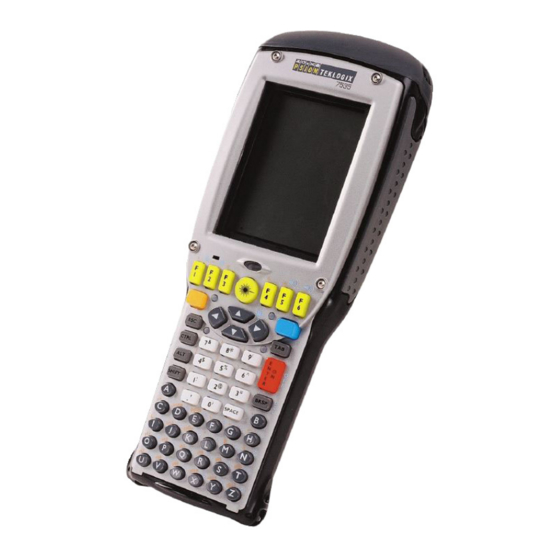
Page 27: The 7535 Hand-Held Computer
Chapter 1: Introduction The 7535 Hand-Held Computer 1.3.2 The 7535 Hand-Held Computer Figure 1.1 7535 With 58-Key Keyboard Teklogix 7535 Hand-Held Computer User Manual... - Page 28 Chapter 1: Introduction The 7535 Hand-Held Computer Figure 1.2 7535 Docking Port Figure 1.3 Tether Port Figure 1.4 Scanner Window Teklogix 7535 Hand-Held Computer User Manual...
-
Page 29: The 7535 Hand-Held Safety Labels
Chapter 1: Introduction The 7535 Hand-Held Safety Labels 1.3.3 The 7535 Hand-Held Safety Labels Figure 1.5 Laser Warning Labels Figure 1.6 Radio Labels Teklogix 7535 Hand-Held Computer User Manual... - Page 30 Chapter 1: Introduction The 7535 Hand-Held Safety Labels Figure 1.7 Manufacturer’s Label Warning: Using controls or adjustments or performing procedures other than those specified herein may result in hazardous radiation exposure. Teklogix 7535 Hand-Held Computer User Manual...
- Page 31 2.6 Uploading New Applications ......29 2.8 Resetting The 7535 Hand-Held ..... . . 30 2.7 Calibrating The Touchscreen .
-
Page 33: Chapter 2: Unpacking & Basic Checkout
Typically, 7535 hand-helds are configured at the factory and arrive ready for use. Although the 7535 is equipped with an internal Compact Flash and SD I/O slot, these slots are not intended for user modification. If a device needs to be changed or added in these slots, contact qualified Psion Teklogix personnel. -
Page 34: Attaching The Hand Strap
Two Phillips head screws are provided with the hand strap. • Attach the strap to the two threaded inserts located at the back of the 7535 near the top of the unit. Figure 2.1 Attaching The Hand Strap... -
Page 35: Attaching The Pistol Grip
Attaching The Pistol Grip Note: A Phillips head screwdriver is required. The pistol grip is attached to the back of the 7535 using the four threaded inserts in the upper part of the 7535 casing. Four black #4-40 Phillips head screws are provided with this accessory. -
Page 36: Powering Up The 7535 And Configuring The Radio
• Position the pistol grip so that it fits snugly over the back of the unit and the inserts on the back of the 7535 align with the holes in the pistol grip. Figure 2.3 Attaching The Pistol Grip •... -
Page 37: Installing The Battery And Switching The 7535 On
2.2.1 Installing The Battery And Switching The 7535 On If you are not using a docking station or PDM: • Slide the charged battery with the moulded plastic facing you into the 7535. Click the battery into place. Figure 2.4 Installing The Battery Note: If you are using a docking station, you can insert an uncharged battery, dock the unit and switch it on. -
Page 38: Configuring An Ieee 802.11 Radio
Important: If the 7535 is equipped with a radio and it has never been config- ured, the radio settings dialogue box opens automatically when the unit is powered on. Follow the directions beginning at Step 4 on page 19 to configure the radio. - Page 39 fields. Use the <LEFT> and <RIGHT> arrow keys to position the cursor in an IP address field. (If you do not have a static IP Address allocated to you, contact your System Administrator.) Teklogix 7535 Hand-Held Computer User Manual...
- Page 40 ESSID. Since access points are generally secure, they will most likely not be listed here; you’ll need to define the access point to which your 7535 will connect. Press the <TAB> key until the <Add...> button is highlighted. Press Wireless Network Properties <ENTER>...
- Page 41 (see Figure 2.8 on page 20). Note: Keep in mind that the 7535 will only communicate with access points that are configured with the same ESSID. Ad Hoc And Infrastructure If you are using an “Infrastructure”...
-
Page 42: Advanced Netwlan Settings
“Configuring An IEEE 802.11 Radio” beginning on page 18. Move up & Preferred Networks Move down Buttons Advanced Button Figure 2.10 Radio Settings Teklogix 7535 Hand-Held Computer User Manual... -
Page 43: Preferred Networks
Each network that you configure is listed in the preferred networks list under ‘Automatically connect to these networks’ . These are the preferred networks that the 7535 attempts to connect with in sequence, beginning at the top of the list. If you need to rearrange this list of networks –... -
Page 44: Configuring Wep Keys
Chapter 2: Unpacking & Basic Checkout Configuring WEP Keys These options specify the type of network connection your 7535 will choose ‘Automatically connect to these networks:’ from the preferred network list labelled (see Figure 2.10 on page 22). ‘Any available network (AP preferred)’... - Page 45 Chapter 2: Unpacking & Basic Checkout Configuring WEP Keys NETWLAN1 802.11b Wireless LAN Settings 3. Choose the icon to open the window. Figure 2.13 802.11b Wireless LAN Settings Window Figure 2.14 Radio Settings Teklogix 7535 Hand-Held Computer User Manual...
- Page 46 Figure 2.15 Wireless Networks Tab 5. Press the <TAB> key to highlight the <Add..> button, and press Wireless Network Properties <ENTER> to display the dialogue box. √ Modify WEP Ke Figure 2.16 Wireless Network Properties Teklogix 7535 Hand-Held Computer User Manual...
- Page 47 9. Press the <TAB> key to move from field to field in this dialogue box. Network key: Used to specify a 5 or 13 ASCII character sequence or an equiv- alent 10 or 26 Hexadecimal digit sequence that matches the active WEP key on the access point. Teklogix 7535 Hand-Held Computer User Manual...
-
Page 48: Additional Radio Security Options
‘Network Authentication’ is enabled (√), the access point sends a known unen- crypted challenge packet to the 7535 radio which encrypts the packet and sends it back to the access point. The access point attempts to decrypt the Teklogix 7535 Hand-Held Computer User Manual... -
Page 49: Checking The Scanner
2.6 Uploading New Applications The simplest way to upload Windows CE.net applications into the 7535 is to use a PDM with a USB equipped PC. Refer to “Portable Docking Module (PDM)” on page 219 for more details about the PDM. -
Page 50: Calibrating The Touchscreen
<BLUE> keys for at least a second. 2.7 Calibrating The Touchscreen If your 7535 is equipped with a touchscreen, it will need to be calibrated. Refer to “Calibrating The Touchscreen” on page 44 for details. 2.8 Resetting The 7535 Hand-Held Note: You do not need to reset your 7535 after configuring the radio. - Page 51 ETTING 3.1 Features Of The 7535 ......33 3.2 The Battery ....... . . 34 3.2.1 Battery Safety .
-
Page 52: Chapter 3: Getting To Know Your 7535
3.12.1 Caring For The Touchscreen ..... 58 3.12.2 Cleaning The 7535 ......58... -
Page 53: Features Of The 7535
Chapter 3: Getting To Know Your 7535 Features Of The 7535 3.1 Features Of The 7535 7535 Screen Ambient Light Sensor Tether Port Docking Port Figure 3.1 Front Of 7535 Scanner Window Stylus (Pointing Tool) Battery Pack Tether Port Figure 3.2 Back Of 7535... -
Page 54: The Battery
Removing The Battery Pack • If your 7535 is equipped with a hand strap, unhook it from the base of the battery. • Press down the release tab at the top of the battery, and slide the battery out. -
Page 55: Charging The Battery
FOR DETAILED INFORMATION about 7535 chargers and docking stations, refer to Chapter 7: Peripheral Devices & Acces- sories beginning on page 205. All batteries must be charged before use. The 7535 battery can be charged with a variety of chargers. These include: •... -
Page 56: Switching The 7535 Hand-Held On And Off
Powered Cradle – can charge the 7535 with the battery installed in the hand-held. It can take from 1.5 to 4 hours to charge a battery. The 7535’s intelligent charging system protects the battery from over-charging by terminating the charge process when the battery is at maximum capacity. -
Page 57: The Keyboard
Important: If the word ‘BLUE’ is displayed in uppercase in the taskbar area at the bottom of the screen, this key is locked “on” – the 7535 will not switch off. Press the <BLUE> key again to unlock it; then press <BLUE>... -
Page 58: Modifier Keys
Chapter 3: Getting To Know Your 7535 Modifier Keys CTRL PQRS WXYZ & BKSP MENU SPACE SHIFT Figure 3.4 58-Key And 36-Key Keyboard Layouts 3.4.1 Modifier Keys The <SHIFT>, <CTRL>, <ALT>, <BLUE> and <ORANGE> keys are modifier keys. Pressing a modifier key changes the function of the next key pressed. For example, on a 58-key keyboard, a square bracket is printed in orange print above the <4>... -
Page 59: Activating Modifier Keys
Activating Modifier Keys When a modifier key is pressed once, it is displayed in lowercase letters in the taskbar at the bottom of the 7535 screen. For example, if the <CTRL> key is pressed, is displayed at the bottom of the unit screen. Once the next key is ctrl key pressed, the modifier key becomes inactive and disappears from the taskbar. -
Page 60: The 58-Key Keyboard
Chapter 3: Getting To Know Your 7535 The 58-Key Keyboard The <TAB> Key Typically, the <TAB> key moves the cursor to the next field to the right or downward. The <ESC> Key Generally, this key is used as a keyboard shortcut to close the current menu, dialogue box or activity and return to the previous one. - Page 61 ‘Accept’ key between alpha selections. The ‘Accept’ key is presented as an arrow ⇒ symbol above the ‘0’ (zero) key. Pressing this key signals the 7535 to display the alpha character you’ve chosen and await the next selection from the same key.
-
Page 62: The Keypad Backlight
Chapter 3: Getting To Know Your 7535 The Keypad Backlight To type the letter ‘b’: • Press the <2> key twice. Press < ⇒> to accept the letter ‘b’. • To type the letter ‘c’: • Press the <2> key three. -
Page 63: The Display
Chapter 3: Getting To Know Your 7535 The Display 3.5 The Display 7535s are equipped with display backlighting to improve character visibility in low light conditions. The unit switches on when a key is pressed and the ambient light is below the set threshold. -
Page 64: Calibrating The Touchscreen
Calibrating The Touchscreen 3.5.3 Calibrating The Touchscreen If your 7535 touchscreen has never been calibrated or if you find that the stylus pointer is not accurate when you tap on an item, use the Stylus Properties dialogue box in the Windows CE Control Panel to recalibrate the screen. -
Page 65: 7535 Hand-Held Computer Indicators
7535s use LEDs (Light Emitting Diode), onscreen messages and audio tones as indicators. 3.6.1 LEDs The 7535 is equipped with four tri-coloured LEDs. This section outlines what these LEDs indicate. Important: If an LED is illuminated in red, the operator should be cautious as this generally indicates an abnormal operating condition or active laser emission. -
Page 66: Charge Leds
Charge LEDs The lower-right LED is reserved for internal charger/power status. This indicator is active even when the 7535 is inserted in a docking station (and in suspend mode) so that the charge status of the battery can be detected easily. -
Page 67: Scan Leds
Figure 3.8 Taskbar This display changes dynamically, and only those icons that are applicable are displayed. For example, if a radio is not installed in your 7535, the radio signal icon is not displayed in the taskbar. Teklogix 7535 Hand-Held Computer User Manual... - Page 68 When the battery level is low – approximately 15 minutes from empty – a warning window pops up. When the battery power is completely depleted, a final warning window indicates that the 7535 will be powered down. Full Empty Radio Signal Quality Increasing radio signal quality is represented by longer, filled bars within this icon.
-
Page 69: Audio Indicators
3.6.3 Audio Indicators The 7535 beeper provides a variety of sounds and can be configured to emit a sound when a key is pressed, a keyboard character is rejected, scan input is accepted or rejected, an operator’s entry does not match in a match field or the battery is low. -
Page 70: Internal Scanners
Chapter 3: Getting To Know Your 7535 Internal Scanners To decrease the beeper volume: • Press the <BLUE> key and then, press the decrease volume function . Repeat this key combination until the volume is low enough for your needs. To work more efficiently with these keys, refer to the note below. -
Page 71: Warnings
Chapter 3: Getting To Know Your 7535 Warnings 3.7.1 Warnings For your own safety, it is critical that you comply with the following warnings: 1. Do not look into the laser beam or point the beam at people or animals. -
Page 72: Scan Led Indicators
Chapter 3: Getting To Know Your 7535 Scan LED Indicators 3.7.3 Scan LED Indicators The 7535 scanner LED (the lower-left LED) indicates whether or not your scan is successful. The LED behaves as follows: • Scan In Progress: scan LED displays solid red colour. -
Page 73: Operating One Dimensional (1D) Internal Laser Scanners
It can find a bar code regardless of its orientation – that is, even a bar code printed at a 45 degree angle to the 7535 will be decoded successfully. Because imager scanners generally have a shorter depth of field than laser scanners, some practise may be required to find the optimal distance from the types of bar... -
Page 74: Connecting & Disconnecting Tethered Peripherals
An icon in the taskbar at the bottom of the screen provides a visual representation of the peripheral and indicates that it is ready for operation. To attach the peripheral to the round, tether port on the side of the 7535: •... -
Page 75: Monitoring The Battery And Maximizing Run Time
Lithium-Ion batteries age, their capacity decreases gradually, and they are generally considered depleted after approximately 2 years of use (less than 60% of original capacity remaining). Keep in mind however that heavy usage or operating the 7535 at temperature extremes will shorten the battery life. - Page 76 • The 7535 battery is a ‘smart battery’ with built-in intelligence. The taskbar battery icon is a linear gauge used to estimate the remaining run time of the battery. It is important to note that the battery capacity icon displays quarter percentages of nominal capacity (the capacity of a new battery).
-
Page 77: Monitoring The Network Connection
Ethernet network. They are typically used to upload transaction data to a server computer when a radio link in not available. When a 7535 is properly inserted in a docking station, a dock icon is displayed in the taskbar at the bottom of the 7535 screen. -
Page 78: General Maintenance
• Avoid abrasive cleaners, solvents or strong chemicals for cleaning. The 7535 has a plastic case that is susceptible to harsh chemicals. The plastic is partially soluble in oils, mineral spirits and gasoline. The plastic slowly decomposes in strong alkaline solutions. - Page 79 4.4 The System Menu ......65 4.5 Using A Dialogue Box ......68 Teklogix 7535 Hand-Held Computer User Manual...
-
Page 81: Chapter 4: Working With Windows Ce
A touchscreen is an optional feature. A 7535 equipped with a touchscreen has a stylus – a pointing tool that looks like a pen – stored in a slot at the top of the 7535. The stylus is used to select objects on the touchscreen. -
Page 82: Working With Files, Folders And Programs
Chapter 4: Working With Windows CE Working With Files, Folders And Programs Keep in mind that unlike a desktop computer, the 7535 does not support key chording (pressing two keys at the same time). You must press one key followed by the next in sequence. -
Page 83: The Startup Desktop
file icon – to open or launch your selection. 4.3 The Startup Desktop When the 7535 boots up, the startup desktop (shell) is displayed. Any applications stored in the Startup folder will start up immediately. Figure 4.2 The 7535 Startup Desktop 4.3.1 Accessing Desktop Icons... -
Page 84: The Taskbar
4.3.2 The Taskbar Figure 4.3 The Taskbar The 7535 is equipped with a taskbar at the bottom of the screen. It displays icons through which you can view the security level, battery capacity and radio signal quality of your unit. If the hand-held is attached to a charger, cradle, docking station or PDM, an associated icon is displayed. -
Page 85: The System Menu
Type the underlined alpha character – for example, to display Windows , type the letter e. Explorer If you have a touchscreen: • Tap on the item in the menu with which you want to work. Teklogix 7535 Hand-Held Computer User Manual... - Page 86 The Control Panel Control Panel contains applets used to configure hardware, the operating system and the shell. If your 7535 is running with the Psion Teklogix Tekterm application or Control Panel another application, additional configuration applets may appear in the Figure 4.5 Control Panel...
- Page 87 • Press <ALT> <ESC>. Note: When the 7535 security level is set to ‘Supervisor’, all the buttons in the sample screen above are accessible. If the security level is set to ‘User’, the ‘Run’ and ‘End Task’ buttons are not visible.
-
Page 88: Using A Dialogue Box
Note: If your unit is equipped with a touchscreen, you can use the stylus to tap on an element in a dialogue box to select or deselect it, display dropdown menu items, save your selections, and so on. Teklogix 7535 Hand-Held Computer User Manual... - Page 89 Saving Your Choices: Once you’ve made all your changes, press the <ENTER> key to save your changes and exit the window. Note: A dialogue box item that is displayed in grey text indicates that it is not currently available. Teklogix 7535 Hand-Held Computer User Manual...
- Page 91 5.5.3.11 I 2 of 5 Settings..... . 101 5.5.3.11 I 2 of 5 Settings..... . 101 Teklogix 7535 Hand-Held Computer User Manual...
- Page 92 5.5.3.12 MSI/PLESSY Settings....102 5.5.3.13 D 2 of 5 Settings ..... . 103 5.5.3.14 IATA 2 of 5 Settings .
-
Page 93: Chapter 5: Configuration
Note: If you are uncertain how to move around a dialogue box and make selec- tions, review “Using A Dialogue Box” on page 68. When the 7535 boots up, the startup desktop (shell) is displayed, and any applications stored in the Startup folder start up immediately. -
Page 94: Control Panel Icons
Sounds (wave files) cannot be reproduced on 7535 units. The beeper volume and the conditions under which it sounds are tailored from within the application installed on your unit. - Page 95 ’ tab, you can recalibrate your touchscreen by tapping on the ‘Recalibrate’ button and following the directions on the calibration screen. System Memory Displays system and memory properties. Under the tab, you can allocate memory between storage memory and program memory. Teklogix 7535 Hand-Held Computer User Manual...
-
Page 96: Basic Setup
’ button allows you to change the type of direct connect to your PC. Network And Dial-up Connections Displays a network window from which the 7535 radio can be configured and an existing configuration can be executed. Refer to “Configuring An IEEE 802.11 Radio”... -
Page 97: Display Contrast
5.3.1.2 Display Backlight The backlight is activated for a configurable amount of time if the ambient light is below a specified threshold and if the 7535 is in use (key press, scanner trigger or Display Properties Control Panel data received from the host). The... - Page 98 The Backlight tab allows you to specify the backlight ‘On Threshold’, ‘Intensity’ and ‘OFF Timeout’. ON Threshold The 7535 is equipped with an ambient light sensor. This sliding bar allows you to determine how dark the ambient light needs to be before the backlight turns on. Teklogix 7535 Hand-Held Computer User Manual...
-
Page 99: Display Appearance
Chapter 5: Configuration Display Appearance Intensity This parameter is used to adjust the light intensity of the 7535 screen. Sliding the bar to the left lowers the light intensity, and sliding it to the right raises the intensity. OFF Timeout... -
Page 100: Keyboard Properties
Control Panel Keyboard • In the , choose the icon. Figure 5.6 Choosing The Keyboard Icon 5.3.2.1 Key Repeat In the Keyboard Properties dialogue box, open the Repeat tab. Figure 5.7 Key Repeat Properties Teklogix 7535 Hand-Held Computer User Manual... -
Page 101: Keyboard Backlight
Intensity This parameter is used to adjust the light intensity of the 7535 keyboard backlight. Sliding the bar to the left darkens the keyboard backlight intensity, and sliding it to the right lightens the intensity. -
Page 102: Keyboard One Shot Modes
‘on’ until they are pressed a second time to unlock them. Note: Keep in mind that the taskbar at the bottom of the screen displays these BLUE KEY ORANGE KEY keys in uppercase characters – – only when they are locked ‘on’. Teklogix 7535 Hand-Held Computer User Manual... -
Page 103: Power Management Properties
Figure 5.10 Choosing The Power Icon 5.3.3.1 Battery Capacity • In the Power Properties dialogue box, open the Battery tab. Figure 5.11 Power Battery Properties Battery tab details information about the battery installed in your 7535. Teklogix 7535 Hand-Held Computer User Manual... -
Page 104: Power Saving Schemes
User Idle State User Idle means that the 7535 is not receiving any user input including activities like a key touch, a scan, and so on – any user initiated activity. When the time selected in Switch state to User Idle User Idle the ‘... -
Page 105: Calibrating The Touchscreen
The state of the device (RAM contents) is preserved. Pressing <ENTER> or the <SCAN> button wakes the system from suspend state. When the 7535 is in suspend state, the network connection is broken. To resume, you must re-establish the network connection. -
Page 106: Advanced Configuration
5.5 Scanner Properties Scanner Properties Control Panel icon in the provides dialogue boxes in which you can tailor bar code options and choose the bar codes your scanner will recognize. Figure 5.15 Bar Code Options Teklogix 7535 Hand-Held Computer User Manual... -
Page 107: Scanner Options
When disabled, these short bar codes are rejected. Enabling “Short Code” may reduce the robustness of the decoding since the 7535 must decode more potential bar codes; it is therefore not recommended for general-purpose bar codes with 4 or more characters. - Page 108 Click Data For both integrated and external scanners, this parameter determines which character is sent to the application installed in your 7535 following a double-click. Enter the ASCII value of the character desired from . You can also press the <LEFT>...
-
Page 109: Bar Codes
‘Settings’ and a ‘Size/Char’ sub-menu. The unit automatically discriminates between the selected codes. Some restrictions may apply. To improve the decode speed and performance, enable ( √ ) only Important: those codes that are required by the application. Teklogix 7535 Hand-Held Computer User Manual... -
Page 110: Bar Code Settings
Code 39 start character. It can be a single alphabetic character or a series of numeric digits followed by an alphabetic character. This identifier defines the general category or specific use of the data contained in the rest of the bar code. Teklogix 7535 Hand-Held Computer User Manual... - Page 111 Chapter 5: Configuration Code 39 Settings Note: If your unit is operating with the Psion Teklogix TESS application, this parameter should not be used in conjunction with the TESS AIAG feature. This is because the 7535 hand-held performs the strip function before it processes the data through the AIAG feature;...
- Page 112 1. The appended character is treated as any other keyboard character. For example, if <BKSP> is pressed, the usual action for that key is performed. If your unit is operating with the Psion Teklogix ANSI emulation application, the 7535 transmits the escape sequence asso- ciated with the function immediately after the bar code data.
-
Page 113: Code 128 Settings
EAN/UCC 128 To successfully scan this type of bar code, “EAN/UCC” must be enabled (√). “EAN/UCC” bar codes include group separators and start codes. Size/Chars Refer to the description beginning on page 91 for details. Teklogix 7535 Hand-Held Computer User Manual... -
Page 114: Ean 13 Settings
Optional, an addendum and if one exists, appends it to the main bar code. When the parameter is set to the scanner does not accept the main bar code Required, without an addendum. Teklogix 7535 Hand-Held Computer User Manual... - Page 115 Note: 1.The appended character is treated as any other keyboard character. For example, if <BKSP> is pressed, the usual action for that key is per- formed. If your 7535 is operating with the Psion Teklogix ANSI emulation application, the hand-held transmits the escape sequence associated with the function immediately after the bar code data.
-
Page 116: Ean 8
Before “Addendum” can take effect, the “Short Code” parameter in the Options menu (see page 87) must be enabled ( √ ). Refer to “Addendum” on page 94. Size/Chars See “Size/Chars” beginning on page 95. Teklogix 7535 Hand-Held Computer User Manual... -
Page 117: Upc And Ean Settings
UPC And EAN Settings Figure 5.23 UPC And EAN Settings Supplementals Enabling (√) this parameter allows supplementary data to be decoded. Size/Char Refer to page 91 for details. 5.5.3.6 UPC A Settings Figure 5.24 UPC A Settings Teklogix 7535 Hand-Held Computer User Manual... -
Page 118: Upc E Settings
5.5.3.7 UPC E Settings Figure 5.25 UPC E Settings Exp to UPC A Enabling (√) this parameter results in a non-standard decoding that returns 12 digits from the 6 digit UPC E bar code. Teklogix 7535 Hand-Held Computer User Manual... -
Page 119: Codabar Size And Characters
Refer to “Addendum” on page 94. Size/Chars Refer to page 95 for details. 5.5.3.8 Codabar Size And Characters Size/Char Refer to page 91 for details. 5.5.3.9 Code 93 Size And Characters Size/Char Refer to page 91 for details. Teklogix 7535 Hand-Held Computer User Manual... -
Page 120: Code 11
If this parameter is enabled (√), it is assumed that the last digit is a check digit. 2 Chk Digits If this parameter is enabled (√), it is assumed that the last two digits are check digits. Size/Chars Refer to page 91 for details. Teklogix 7535 Hand-Held Computer User Manual... -
Page 121: I 2 Of 5 Settings
If this parameter is enabled (√), the ITF-14/16 Mod10 check digit is calculated. Include Chk If this parameter is enabled (√), the check digit is included with the decoded bar code data. Size/Chars Refer to page 91 for details. Teklogix 7535 Hand-Held Computer User Manual... -
Page 122: Msi/Plessy Settings
If this parameter is enabled (√), it is assumed that the last digit is a check digit. Include Chk If this parameter is enabled (√), the check digit is included with the decoded bar code data. Size/Chars Refer to page 91 for details. Teklogix 7535 Hand-Held Computer User Manual... -
Page 123: D 2 Of 5 Settings
If this parameter is enabled (√), the ITF-14/16 Mod10 check digit is calculated. Include Chk If this parameter is enabled (set to “Y”), the check digit is included with the decoded bar code data. Size/Chars Refer to page 91 for details. Teklogix 7535 Hand-Held Computer User Manual... -
Page 124: Iata 2 Of 5 Settings
If this parameter is enabled (√), the check digit is included with the decoded bar code data. Size/Chars Refer to page 91 for details. 5.5.3.15 Postal: Australian Size/Chars Refer to page 91 for details. Teklogix 7535 Hand-Held Computer User Manual... -
Page 125: Postal: Japanese
Refer to page 91 for details. 5.5.3.18 Postal: PlaNET Size/Chars Refer to page 91 for details. 5.5.3.19 Postal: PostNET Size/Chars Refer to page 91 for details. 5.5.3.20 Postal: Royal Mail Size/Chars Refer to page 91 for details. Teklogix 7535 Hand-Held Computer User Manual... -
Page 126: Datamatrix (2D)
If enabled (√), DataMatrix symbols of small physical size can be successfully decoded. Size/Chars Refer to page 91 for details. 5.5.3.22 Maxicode (2D) Size/Chars Refer to page 91 for details. 5.5.3.23 PDF-417 (2D) Size/Chars Refer to page 91 for details. Teklogix 7535 Hand-Held Computer User Manual... -
Page 127: Micro Pdf-417 (2D)
If enabled (√), this parameter allows symbols that contain light cells on a dark background to be decoded. Size/Chars Refer to page 91 for details. 5.5.3.26 RSS Code (2D) Size/Chars Refer to page 91 for details. 5.5.3.27 Aztec Size/Chars Refer to page 91 for details. Teklogix 7535 Hand-Held Computer User Manual... - Page 129 6.6 ANSI Emulation ....... 128 Teklogix 7535 Hand-Held Computer User Manual...
- Page 130 6.8.4 Retrieving Default Parameter Values ....139 6.9 Resetting The 7535 Hand-Held Computer ....139 6.10 The Parameters Menu .
-
Page 131: Chapter 6: Tekterm Application
6.17.2.8 Anchor View ......190 6.18 Ports– Tether And Console ......191 Teklogix 7535 Hand-Held Computer User Manual... -
Page 132: Chapter 6: Tekterm Application
6.19.2 802.IQ v2 .......202 Teklogix 7535 Hand-Held Computer User Manual... -
Page 133: The Tekterm Application
The 7535 is equipped with a series of function key. The function of each of these keys is defined in the application software. Depending on the type of keyboard your 7535 has – 58-key or 36-key – the number and location of the function keys on the keyboard varies slightly. -
Page 134: Softkey Function Keys
If your 7535 is equipped with a touch- screen, you can tap the stylus on the appropriate softkey label, providing that the labels are visible at the bottom of the 7535 screen. See “Softkeys” on page 149 if they are not visible. -
Page 135: Macro Keys
6.2.2 Macro Keys 7535 hand-helds are equipped with a series of macro keys that can be programmed to replace frequently used keystrokes, along with the function of executable keys like the <ENTER> key, the <BKSP> key, any function key and arrow key, and so 58-Key Keyboard Macro Keys 7535s with 58-key keyboards have twelve macro keys –... -
Page 136: Keyboard Modes
Press <CTRL> <ALT> <V> to exit View mode. 6.3.1.2 Panning The Screen Contents If the content of a screen is too large to fit in the margins of the 7535 display, the contents can be panned or shifted to bring the information outside the margins into view. -
Page 137: Exiting View Mode
Note: You can press the <BLUE> key followed by the appropriate arrow key each time you want to pan the contents one increment at a time in the direction of the arrow key without placing the 7535 in View mode. Teklogix 7535 Hand-Held Computer User Manual... -
Page 138: Menu Mode And Switching Between Applications
When the keyboard is in Menu mode, the System Menu is displayed so that you can move between active applications. (More information about System Menu items is provided in Chapter 4, beginning on page 65.) To place the 7535 in Menu mode: • Press <BLUE> <0> (zero). -
Page 139: The Tekterm Status Area
User, Supervisor or Teklogix Within Tekterm status area. One of the following is displayed – When <CTRL><ALT><V> is typed to place the 7535 in View mode, this View Mode information is displayed in the status area. Table 6.2 Status Area... -
Page 140: Tess Emulation
Note: If the message “RESET: Press Enter” flashes at the bottom of the TESS screen when you turn on the 7535, press the <ENTER> key once. 6.5.1 Configuration Note: Each TESS session must have a unique name assigned to it. The title you assign will be displayed in the Display Menu. -
Page 141: Ibm 5250 Emulation Keys
Home (Home key) 6.5.5 Data Entry The 7535 accepts data until the operator presses a key that sends a transmission to the host computer. The following actions cause the 7535 to transmit: • Pressing a function key or the <ENTER> key (which is considered to be <F0>) causes the 7535 to transmit. -
Page 142: Tess Edit Modes And Cursor Movement
Chapter 6: Tekterm Application TESS Edit Modes And Cursor Movement There are several ways to configure the 7535 hand-held to complete a data field: • Pressing <ENTER> after entering data. • Pressing a function key after entering data. • Pressing an arrow key after entering data. -
Page 143: Del> Key Behaviour In Tess
• If the <DEL> key is pressed while cursor is in the right most Replace mode position in the field, the 7535 emits a keyboard error beep. • If the <DEL> key is used to clear data in a field that has been pre-filled by the host application, the field is flagged as modified... -
Page 144: Bksp> Key Behaviour In Tess
Field mode modified, and the field is opened. • If the <BKSP> key is pressed when the field is empty, the 7535 emits a keyboard error beep. • The <BKSP> key does not delete data pre-filled by the host applica- tion. -
Page 145: Tess Status Message
Press <CTRL> <S> to continuously display the status message in the lower left corner of the screen. • Press <CTRL> <W> to make this message appear only when the 7535 locks. The message should look similar to the sample below: V6.0 fld 0.6 “V6.0”... -
Page 146: Lock Messages
Lock-B/Lock-H “application name” • <CTRL> <W> – Displays the 7535 status when the unit is in “Lock B” or “Lock H” mode. The status line would be similar to the sample above. • <CTRL><T> – Displays the 7535 status with the terminal number instead of the name. -
Page 147: The Local Menu
Chapter 6: Tekterm Application The Local Menu 6.5.10 The Local Menu The host can store local procedures in the 7535 for use when the unit is off-line. A menu of these procedures appears whenever <CTRL> <L> is pressed (see Figure 6.3). -
Page 148: Queuing Mode
This means software that supports ANSI terminals requires little or no changes. 6.6.1 Configuration To configure the 7535 for ANSI mode, the “Name” and “Type” of session – in this case, ANSI – must be specified in the Applications menu. This menu is described in the section titled, “Applications”... -
Page 149: Sending Data To The Host
The 7535 provides parameters that determine when the computer transmits characters to the host. The 7535 can be configured to transmit after a number of characters are typed in (the “Xmit Count” parameter) or after some time has elapsed (the “Xmit Wait”... -
Page 150: Block Mode (Local Editing)
Table 6.3 Psion Teklogix Keyboard And VT220 Equivalent Keys 6.6.4 Block Mode (Local Editing) The Psion Teklogix 7535s support “block mode” (or Local Editing). Application programs must be specifically written to support this mode. For software that supports this mode, the keys shown in Table 6.4 have special meaning. -
Page 151: Working With Sessions
Press <CTRL>, and type a lowercase a. • At the TCP> prompt, type cl in lowercase letters followed by the session number you want to close. e.g., Type cl 2 to close session 2. • Press <ENTER>. Teklogix 7535 Hand-Held Computer User Manual... -
Page 152: Printing A Screen
6.7 The Tekterm Startup Display Menu The values assigned to Tekterm parameters can be viewed and adjusted to optimize communication at the site in which a 7535 is operating. While some parameters are accessible through the “Parameter Manager”, others can be adjusted through the Windows CE Control Panel. -
Page 153: Working With Menus
Note: To return to the ‘Display Menu’, press <F2> – the ‘Previous’ key. 6.8 Working With Menus The 7535 offers two ways to navigate menus and choose values – you can either use the keyboard or, if your unit is equipped with a touchscreen, you can select items by tapping a stylus on the screen. -
Page 154: Numeric Parameters
Alpha characters appear in reverse video in this type of parameter. The allowable values for alpha parameters consist of a predetermined set of acceptable letters or words. To cycle through the set: • Press the <RIGHT> or <LEFT> arrow keys. Teklogix 7535 Hand-Held Computer User Manual... -
Page 155: String Entry Parameters
By pressing either the <RIGHT> or <LEFT> arrow key, you can cycle through a set of printable characters not directly accessible from the keyboard. • Press the <RIGHT> arrow to display the next character in this sequence, and the <LEFT> arrow to display the previous one. Teklogix 7535 Hand-Held Computer User Manual... - Page 156 Unicode is a trademark of The Unicode Consortium. To enter a Unicode™ value for one-time use: • Press and hold down the <ALT> key while typing a four digit decimal value that represents the Unicode™ character you want to display. • Release the <ALT> key. Teklogix 7535 Hand-Held Computer User Manual...
-
Page 157: Using The Touchscreen To Navigate Through Menus
1 through 10. If you attempt to enter a number which either exceeds 10 or falls below 1, the incorrect value will be rejected – the original value for this parameter, if any, will be displayed. Teklogix 7535 Hand-Held Computer User Manual... -
Page 158: Y/N Parameters
If the softkey labels are not visible, you’ll have to press <F4> – the “SAVE” function key. If a parameter value is changed and the menu exited before the change is saved, a dialogue box appears asking whether or not the operator wants to save the changes. Teklogix 7535 Hand-Held Computer User Manual... -
Page 159: Retrieving Default Parameter Values
A reset results in a complete reboot of the unit. All RAM memory contents are lost. The contents of the flash memory and memory card are preserved. When the 7535 is reset, the screen displays the Psion Teklogix and Microsoft® Windows® CE.net splash screen before displaying the startup desktop. -
Page 160: Security Settings
“User” options. 6.11 Display Options The ‘Display’ sub-menu is used to adjust your unit’s display properties. • Press <F1> to access the ‘Display’ sub-menu. Display Range Backlight Ctrl Panel » see text Teklogix 7535 Hand-Held Computer User Manual... -
Page 161: More Parameters
Chapter 6: Tekterm Application More Parameters The Display Properties dialogue box is displayed where you can adjust the appearance, backlight and contrast of your 7535 display. Figure 6.5 Display Properties Important: ‘Display Properties’ dialogue box options are described in detail beginning on page 77. -
Page 162: Radio Parameters
6.13 Radio Parameters Important: Radio parameters should not be changed from their factory settings without a clear understanding of your system. The 7535 is equipped with an Intel 802.11b radio. • Press <F1> to display the ‘Radio’ sub-menu. Radio 802.11 »... - Page 163 Radio Address The value entered in the “Radio address” parameter is used to identify the 7535 over the radio link. A unique value from 1 to 3840 must be assigned for each 7535 hand-held computer. Initial RTT (Round Trip Time) Round trip time is the elapsed time between a hand-held computer transmission and an access point acknowledgement.
- Page 164 Protocol Type “Protocol Type” is used to identify the Ethernet packet frame type sent by the 7535. The default value – – assigned to this parameter identifies the Teklogix 802.IQ 2457 protocol Ethernet packet frame types.
-
Page 165: System Parameters
From the “Display Menu”, type the letter a to display the “Parameters” menu. • In the “Parameters” menu, highlight “System”, and press <F1>. Parameters Radio » System » Scanner Ctrl Panel» View Manager » Applications » Ports » Network » Teklogix 7535 Hand-Held Computer User Manual... - Page 166 Once the cursor is in a macro field, you have a number of options when creating a macro. You can type text and numbers, choose from a set of ASCII characters and program the function of special keys into a macro. Teklogix 7535 Hand-Held Computer User Manual...
- Page 167 When you’ve chosen an ASCII character and want to add another one in the same field, the cursor must be moved to the right of the existing character. Normally, pressing the <RIGHT> arrow key moves the cursor to the right, but in a string entry Teklogix 7535 Hand-Held Computer User Manual...
-
Page 168: Indicators
6.14.1.2 Indicators When the “Indicators” parameter is enabled (set to “Y”), onscreen indicators are displayed to indicate the operating condition of the 7535. Refer to “Onscreen Indicators” on page 47 for a list of possible indicators. Teklogix 7535 Hand-Held Computer User Manual... -
Page 169: Softkeys
<BLUE> and <ORANGE> keys. Figure 6.6 Keyboard Properties Important: Refer to “Keyboard Properties” on page 80 for details about this dialogue box. Teklogix 7535 Hand-Held Computer User Manual... -
Page 170: Audio
These parameters regulate the frequency and duration of beeps emitted in a TESS or ANSI session when one of the following is received at the 7535: an advisory, a hey you or a bell character. Tone is measured in hertz and time in milliseconds. -
Page 171: Power Mgmt
Power Mgmt 6.14.3 Power Mgmt This menu item displays the Power Properties dialogue box that displays the battery capacity of the 7535 and allows you to manage battery use. Figure 6.7 Power Properties Dialogue Box Important: Refer to “Power Management Properties” on page 83 for details about this dialogue box. -
Page 172: User Level Options
Screen Switch When set to “Y”, the operator can use the “Split screen” parameter to toggle between screens when multiple applications are running on the 7535. Refer to “Split Screen” on page 155 for details about using this function. Font Chg When “Font Chg”... -
Page 173: Scanner Control Panel
Figure 6.8 Scanner Properties Dialogue Box Important: Refer to "Scanner Properties" beginning on page 86 for details about setting up your scanner. Teklogix 7535 Hand-Held Computer User Manual... -
Page 174: View Manager
Increment” is set to “Y”. Y-increment This parameter determines the number of spaces the screen shifts once the cursor moves out of view. The value assigned here doesn’t take effect until “Use Increment” is set to “Y”. Teklogix 7535 Hand-Held Computer User Manual... -
Page 175: Split Screen
“Type” and “View IDs”, are used to tailor the screen view for your needs. Type And View IDs The “Type” parameter determines how a screen will be split. The 7535 supports up to four application screens. The “View IDs” parameter determines which application screens will be displayed in each pane of the split screen. -
Page 176: Moving Between Split Screens
2 Way ||| View IDs • Press <ENTER>. To display the split screen on the 7535: • Press <CTRL> <DOWN> arrow. 6.16.1.2 Moving Between Split Screens To move the cursor from one pane in a split screen to the next: •... -
Page 177: Using The Asterisk As A Wild Card
• In the Parameters menu, highlight “View Manager” and press <F1>. Teklogix 7535 Hand-Held Computer User Manual... -
Page 178: Displaying The Unicode™ Pop-Up Window
• Press <F4> to save your changes. • Reset the 7535 – press and hold down the <ENTER> and <BLUE> key simultaneously for a minimum of six seconds. 6.16.2.2 Displaying The Unicode™ Pop-up Window The Unicode™ values you create are stored in a pop-up window that you can access from any application. - Page 179 18x32 Font Code ... is font 10x26 Font Code ... is font 18x32 Font Code ... is font 8x20 This parameter is used to redefine the font to which 5 different font codes refer. Teklogix 7535 Hand-Held Computer User Manual...
-
Page 180: Applications
Magenta Cyan White Black Note: The 7535 must be reset – press and hold down the <BLUE> and <ENTER> keys for a minimum of six seconds – in order for the new colour assignments to take affect. 6.17 Applications “TESS” and “ANSI” applications require unique names so that several different sessions of “TESS”... -
Page 181: Ansi Settings
» see text Host Char Set » see text Anchor View N» see text Each session you create has its own “Settings” parameters. Additional ANSI information is documented in “ANSI Emulation” on page 128. Teklogix 7535 Hand-Held Computer User Manual... -
Page 182: Host Conn
This parameter defines the number for the ANSI session and uniquely identifies all transmissions to and from the 7535. Other applications running in the 7535, such as a TESS session or another ANSI session must each have a different number. In addition, each Psion Teklogix 7535 using the radio link must have a unique number. -
Page 183: Screen
There is no error indication from the hand-held computer if the memory required by the selected number and size of pages exceeds the memory available in the computer. Teklogix 7535 Hand-Held Computer User Manual... - Page 184 Note: The value in this parameter must be an even number. Default font This parameter determines the default font that appears when the 7535 memory is reset. The allowable values are: 16x30...
- Page 185 “Underline” ANSI attribute. Label F1-F6 Note: This menu uses string entry fields. For detailed information about com- pleting this type of field, refer to “String Entry Parameters” on page 135. Label F1-6 • • • Teklogix 7535 Hand-Held Computer User Manual...
-
Page 186: Xmit Modes
6.17.1.3 Xmit Modes Range Xmit Modes Xmit Count 0..99 Xmit Wait 0..999 Dev Attr [ ? 62 ; 1 ; 2 ; 6 c see text Auto-Answer see text 7 bit Block Mode » see text Teklogix 7535 Hand-Held Computer User Manual... - Page 187 Auto-Answer This string can be up to 30 characters long and is sent by the 7535 as a reply to an “ENQ” character from the host. The “Auto-Answer” string is programmable in the same manner as the keyboard macros.
- Page 188 Terminal Programmer’s Manual for more information. Kbd lock When this parameter is disabled (set to “N”), the 7535 does not lock the keyboard after a block mode transmission. When enabled (set to “Y”), the keyboard is locked after a transmission. The application program must unlock the keyboard by resetting the Keyboard Action Mode (KAM), using the Reset Mode (RM) or Enable Manual Input (EMI) controls.
- Page 189 This string entry parameter specifies a string of up to 8 characters that are sent after each line in a block transmission. If the parameter is not used, the rules specified in “Transmitted Data Stream” are used to determine end of line characters. Teklogix 7535 Hand-Held Computer User Manual...
-
Page 190: Kbd Modes
field in the direction of the arrow. When set to “cursor”, pressing the <LEFT> and <RIGHT> arrow keys move the cursor within the current field. Echo Mode This parameter selects echo mode for the 7535. The available modes are “Local”, “Host”, and “Smart”. Local: In this mode, any character entered using the keyboard is displayed before being sent to the host. - Page 191 The maximum number of characters waiting for echo is 25. Any additional characters are sent to the host but not displayed. When the 7535 is in insert mode, smart echo is disabled. Function In newline mode, this key moves the cursor to the first ENTER column of the next line.
- Page 192 Chapter 6: Tekterm Application Kbd Modes Note: The 7535’s port must be set to “printer” (see“Ports– Tether And Con- sole” on page 191). Xmit Enter The <ENTER> key normally enters data into a field and moves the cursor to the next field.
-
Page 193: Edit Modes
ANSI mnemonics are displayed in reverse video. Other characters are displayed as normal characters. This mode can also be set with the Set Mode (SM) control but can only be reset from the Parameters menu. Teklogix 7535 Hand-Held Computer User Manual... -
Page 194: Serial
ANSI print commands (such as ‘MC’ or Media Copy) control the transfer of data to and from the serial and console ports on the 7535. At the 7535, the value assigned at the ‘Primary Port’ and ‘Secondary Port’ parameters determines which port the ANSI print command will identify and use as primary and secondary. -
Page 195: Anchor View
The “x origin” parameter is used to specify the column to which the upper left corner of the screen will be anchored. The “y origin” parameter is used to specify the row coordinate to which the screen will be anchored. Teklogix 7535 Hand-Held Computer User Manual... -
Page 196: Tess Settings
For every application session you create, the “Terminal #” assigned must be non- zero and unique. This parameter defines the terminal number for the TESS session and uniquely identifies all transmissions to and from the 7535. Teklogix 7535 Hand-Held Computer User Manual... -
Page 197: Host Conn
Chapter 6: Tekterm Application Host Conn. Other applications running in the 7535, such as an ANSI session or another TESS session must each have a different number. In addition, each Psion Teklogix 7535 using the radio link must have a unique number. -
Page 198: Screen
This parameter defines the logical page width (in characters) used by the host computer application. Emulator systems trim the host application screens to this width. This page width cannot be smaller than the width of the 7535 display. Display panning is used if the page is wider than the display. - Page 199 This parameter determines the number of pages that can be stored and recalled at the 7535. Storing frequently used page data at the 7535 reduces the need for the host to retransmit complete page data over the radio link. Retransmitting data can reduce the system response time.
-
Page 200: Characters
Misc. N » This menu contains all the character sets available with your Psion Teklogix computer. In this menu, the “Y” or “N” is used to visually guide you to the selected character set. For example, in the sample menu above, the “Y” next to IBM indicates that a character set has been chosen from this group. - Page 201 field match data from the host. Field matching allows the host to pre-load data into an entry field that is compared with the user’s input. The 7535 beeps if the entered data does not match. Hidden field matching means that the data to be matched is not displayed in the entry field.
-
Page 202: Tests
The value represents the number of the function key – not the ASCII decimal equivalent. After sending this key, the unit locks and waits for the host to unlock the 7535. To disable “AutoRep Fn”, set the “AutoRep T/O” parameter to zero. AutoRep T/O This parameter determines the time (in seconds) between the 7535 unlocking and the next transmission of the function key specified by the above parameter. -
Page 203: Features
The menu item “Local Process” has a sub-menu attached to it – “Save on Reset”. When this parameter is enabled (set to “Y”), data stored in the 7535 is saved if the unit is reset. Local procedures are defined on page 127. - Page 204 TESS print commands control the transfer of data to and from the serial and printer ports on the 7535. At the 7535 computer, the value assigned at the ‘Serial Port’ parameter ranks which port the TESS print command will identify and use as the first to fourth port.
- Page 205 Also, when this parameter is enabled (set to “Y”), each time a DLE (^P=0x10) character is encountered in the serial input, it is removed and the character following it will be replaced with its 1’s complement. Teklogix 7535 Hand-Held Computer User Manual...
-
Page 206: Scanner
DLE is inserted to precede that character. The control character is replaced with its 1’s complement. 6.17.2.6 Scanner Scanner Range Cont Nxt Fld Append Enter Append F0 Mixed AIAG Rjct if Alpha Beam Lockout Teklogix 7535 Hand-Held Computer User Manual... - Page 207 When the cursor is in a numeric field and “Rjct if Alpha” is enabled (set to “Y”), bar codes containing alphabetic characters are rejected. Beam Lockout When enabled (set to “Y”), this parameter disallows scanner use when the current session is in “LOCK-H” mode. Teklogix 7535 Hand-Held Computer User Manual...
-
Page 208: Fields
The <ENTER> key normally enters data into a field and moves the cursor to the next field. However, some applications require that the <ENTER> key start a transmission from the 7535. When enabled (set to “Y”), this parameter causes the <ENTER> key to be interpreted as <F0> which starts a transmission. - Page 209 (Traditional Chinese), (Korean), (Thai), 10x9 10x15 11x10 12x24 13x12 (Traditional Chinese), (Korean), 13x15 13x20 14x30 15x21 16x15 16x15 (Simplified Chinese). 16x15 • Use the <RIGHT> or <LEFT> arrow key to scroll through the options. Teklogix 7535 Hand-Held Computer User Manual...
-
Page 210: Anchor View
fields. Enh Edit Mode This mode provides extended (enhanced) functions to users of Psion Teklogix’ IBM 5250 terminal emulation. When this parameter is enabled (set to “Y”), the arrow keys move the cursor anywhere on the screen, unrestricted by fixed or entry fields. -
Page 211: Ports- Tether And Console
Disabled – indicates that the serial port is not being used. • Serial – standard serial port. • Console – used to connect another PC to the 7535. A communication program is required so that communication can proceed between the 7535 and the PC. •... -
Page 212: Tether And Console Port Parameter Settings
Misc. N » This menu contains all the character sets available with your Psion Teklogix computer. In this menu, the “Y” or “N” are used to visually guide you to the selected character set. For example, in the sample menu above, the “Y” next to IBM indicates that a character set has been chosen from this group. - Page 213 Flow Control This parameter selects the type of flow control used in your hand-held computer. The 7535 can perform XON/XOFF (Software) handshaking. The function of each mode is as follows: Enable: Used to input and output data. Supports XON/XOFF or no handshaking.
- Page 214 If the count specified in this parameter is exceeded, the transmission fails. Input Tmo This parameter sets the time in tenths of a second that the 7535 waits before passing received data to the TESS or ANSI tasks. Output Tmo The value assigned at this parameter determines the maximum number of milliseconds that the application will wait for a ‘write’...
-
Page 215: Tether And Console Port Scan-See Parameters
6.18.3.1 Scan-See Sub-Menu – Mapping The Viewport Range Scan-See Anchor Line 0...1 Anchor Column 0...19 Follow Cursor Line Offset -25...25 Column Offset -80...80 Wraparound Panning Line Scrolling Brightness 0 to 5 Arrows Bright Bright Horz Vert Version 0...2 XON/XOFF Teklogix 7535 Hand-Held Computer User Manual... - Page 216 A location on the Scan-See display – the anchor – is chosen as a reference point. Line Offset/Column Offset A predefined displacement – the offset – is added to the location of the 7535 cursor to create a point – the pivot . This pivot is mapped to the anchor , and whatever is displayed in its vicinity is also displayed on the Scan-See.
- Page 217 Each time the <LEFT> arrow is pressed, the number is decremented by one. For example, to enter a value of “–5”, start from zero and press the left arrow key five times. Teklogix 7535 Hand-Held Computer User Manual...
- Page 218 Scan-See display. However, the Scan-See display is updated to reflect the changes within that viewport. If the pivot goes outside the viewport, or if the 7535 display changes without the cursor being moved, the viewport is re-synchronized to coincide the pivot with the anchor.
- Page 219 • Psion Teklogix 7000M LCD units; these are encased in black plastic. Table 6.7 Scan-See Versions Note: To interface the 7535 to the Scan-See units with older firmware (serial number lower than 1594120224), set “Parity = space”; all other parameters are identical to the newer firmware.
-
Page 220: Scan-See Keyboard Mapping
Bar-code data is stripped off any identifying headers (symbology, etc.) and passed verbatim. The Scan-See is capable of displaying only a subset of the default PC-8 ASCII character set. Any characters that cannot be displayed are currently translated to ‘.’. Teklogix 7535 Hand-Held Computer User Manual... -
Page 221: Network
» 6.19.1 Network Ctrl Panel Settings This option displays a Windows CE screen where you can set up your radio, launch an existing network connection or create a new connection. Figure 6.9 Network Settings Teklogix 7535 Hand-Held Computer User Manual... -
Page 222: Netwlan - Configuring The Radio
“Port” specifies the UDP port used by 802IQ v2. The default value is 8888. Keep in mind that the value assigned here must match the value set at the network controller. Note: When using 802.IQ v2, make certain that the 7535 “Net Mask” matches the network controller net mask. - Page 223 The 802.IQ radio items listed in this menu are only available to Psion Teklogix personnel. Auto Radio Addr If this parameter is set to “Y”, the 7535 requests an automatically assigned radio address. Note: If ‘Auto Radio Addr’ is enabled (set to “Y”), any value assigned to the ‘Radio Address’...
- Page 225 7.1.2 Entering Data With The Bar Code Reader....207 7.2 The 7535 Battery ....... 207 7.2.1 Lithium-Ion Battery Safety Precautions .
- Page 226 7.10 Bluetooth Peripherals......222 7.11 The 7535 Picker Cradle ......222 7.11.1 Mounting Recommendations .
-
Page 227: Chapter 7: Peripheral Devices & Accessories
To connect this scanner to the 7535, attach the device to the tether port at the upper- right side of the 7535. Before using the bar code reader, you may need to change some parameters. -
Page 228: Lithium-Ion Battery Safety Precautions
It is critical that this safety information be reviewed and that all warnings be strictly followed. Warning: BATTERIES ARE CONSIDERED HAZARDOUS WASTE and must be returned to Psion Teklogix for proper disposal. All used batteries must be forwarded to one of the following offices: Psion Teklogix Inc. Psion Teklogix Corp. -
Page 229: Important Charger Safety Instructions
The plug pins on the extension cord are the same number, size, and shape as those on the charger. • The extension cord is properly wired and in good electrical condition and that the wire size is larger than 16 AWG. Teklogix 7535 Hand-Held Computer User Manual... -
Page 230: Chargers
Note: The full capacity of the battery may not be reached until at least 5 full charge/discharge cycles have been performed. It can take from 1.5 to 4 hours to charge a battery. The 7535’s intelligent charging system protects the battery from over-charging by terminating the charge process when the battery is at maximum capacity. -
Page 231: Operator Controls
Each battery charge slot is equipped with a tri-coloured LED to indicate the charge status of the battery. When 7535 batteries are inserted in the charger, the colour and behaviour of the LEDs associated with the charge wells in use indicate the status of the charge. -
Page 232: Charging Batteries
If any of the charge slot LEDs continue to flash red, the charger is defective and requires service. If all indicators are flashing red, there is a power supply problem and the charger requires service. Teklogix 7535 Hand-Held Computer User Manual... -
Page 233: Power Led Does Not Light Up
7.6 Combo Charger The 7535 combo charger is a desktop charger designed to charge the 7535 internal battery along with a spare battery pack. The combo charger provides sufficient power to operate and fast charge the 7535 internal battery, while recharging the spare battery pack. -
Page 234: Operator Controls
The battery charge LED on the 7535 lights up indicating that the unit has external power and battery charging may begin. It is safe to leave the 7535 in the combo charger cradle while it is not in use – the battery will not be overcharged. -
Page 235: Charge Indicators
Table 7.2 Combo Charger Indicators The combo charger supplies DC power to enable the 7535 internal fast charger. Charge status is displayed on the 7535 charge LED – the lower-right LED. Refer to “Charge LEDs” on page 46 for details. -
Page 236: Combo Dock
A green LED is illuminated next to the RJ45 connector when a valid network link is established. A user application needs to be loaded onto each 7535 that utilizes the combo dock for communication. With the network connected and this application loaded, the combo dock is ready for use. -
Page 237: Troubleshooting
A green LED is illuminated next to the RJ45 connector when a valid network link is established. A user application must be loaded onto each 7535 that utilizes the quad dock for communication. When the network is connected and this application is loaded, the quad dock is ready for use. -
Page 238: Indicators And Controls
TCP/IP protocol to name, locate and communicate with a 7535 on the network. If a link is established between a 7535 and a host, the application on the host and on the 7535 must have a recovery mechanism in the event that the 7535 is removed from the dock and the link is interrupted. -
Page 239: Battery Charging
7535 charge LED (see “Charge LEDs” on page 46). Battery charging continues whether the 7535 is switched on or off. Normally, it takes between 1.5 and 4 hours to fully charge the 7535 internal battery. 7.8.6 Troubleshooting The indicators, applications and drivers required to use and monitor the docking station are installed on the 7535 –... - Page 240 Align the pins on the PDM with the connectors on the base of the 7535, and gently snap the PDM onto the hand-held. Connector Pins Figure 7.1 Snapping The PDM To The Base Of The 7535 Teklogix 7535 Hand-Held Computer User Manual...
- Page 241 DC power supply provided with your PDM. The DC power supplied by the PDM is sufficient to operate the 7535 and fast charge its internal battery at the same time. The 7535 can run from a PDM without a battery installed.
-
Page 242: Bluetooth Peripherals
Bluetooth Peripherals 7.10 Bluetooth Peripherals If the 7535 is equipped with a Bluetooth radio, it is possible to communicate with a variety of Bluetooth peripherals, including GSM/GPRS handsets, scanners, printers, and so on. The range of the Bluetooth radio in the 7535 is limited to approximately 2 meters. -
Page 243: Mounting Recommendations
To accommodate the surface loop of the connector cable, leave a 4" clearance at the bottom of the cradle. Leave a 7" clearance at the top of the cradle to allow easy removal of the 7535. Refer to the detailed assembly instructions that are packaged with the cradle for this application (PN TBD) 7.11.1.1 Mounting Template... -
Page 244: Wiring Guidelines
• Slide the 7535 into the cradle, and press downwards until it locks into place. On a vehicle, it’s a good idea to pull up on the 7535 to be certain that it is secure. •... -
Page 245: The Powered Cradle Option
The Powered Cradle Option 7.11.5 The Powered Cradle Option The powered cradle option is designed to allow the 7535 to be powered by a vehicle battery. The battery installed in the 7535 is also recharged by the vehicle battery. This option accepts DC power sources over the range 12V to 90V. -
Page 246: The Port Replicator
The functionality of the 7535 tether port is duplicated on the port replicator. When the 7535 is installed in a port replicated picker cradle, the tether port on the 7535 is disabled and the tether port on the port replicator is enabled. Although it is not necessary to remove a device connected to the 7535, keep in mind that it will not operate while in the cradle. - Page 247 PECIFICATIONS 8.1 7535 Hand-Held Computer Specifications ....229 8.2 Radio Specifications ......230 8.3 Bar Code Scanning .
-
Page 249: 7535 Hand-Held Computer Specifications
Environmental Operating Temperature 0˚C to +50˚C (32˚F to +122˚F) Short exposure to temperatures outside this range may cause the 7535 screen to become very dark or light temporarily. Long exposure to temperatures below -40˚C (-40˚F) may damage the screen. Prolonged exposure to temperatures above +60˚C... -
Page 250: Radio Specifications
Decoded and non-decoded. Non-Decoded Codes Supported Code 39, code 128, EAN 13, EAN 8, EAN 128, UPC-A, UPC-E, Codabar, Code 93, Code 11, Interleaved 2-of-5, MSI/PLESSY, Discrete 2-of-5. Decoded Codes Supported Dependent on external scanner choice. Teklogix 7535 Hand-Held Computer User Manual... -
Page 251: Internal Scanners
8.3.2 Internal Scanner Port Compatibility Symbol SE1200HP, SE1200LR, SE1200ALR, SE1200WA SE122x, SE2223 2-D 8.3.3 External Scanners Supported Types Decoded and Non-Decoded 5V only. Interface Via tether port. 8.4 Internal Scanner Specifications Teklogix 7535 Hand-Held Computer User Manual... -
Page 252: Se1200 High Performance & Long Range Specs
675 nm. tance measured at 675 nm. Ambient Light Sunlight: 8000 ft. candles Sunlight: 8000 ft. candles Immunity Artificial Light: 450 ft. candles Artificial Light: 450 ft. candles Table 8.1 SE1200HP And SE1200LR Scanner Specifications Teklogix 7535 Hand-Held Computer User Manual... -
Page 253: Se1223 Advanced Long Range & Se2223 2-D Specs
450 ft.-candles/4,844 lux Artificial: 8,000 ft. candles (86,112 lux) 8,000 ft.-candles/86,112 lux Sunlight: with correct enclosure. 22º to 140° F/-30º to 60º C @ Operating Temperature: -22º to 131ºF (-30º to 55ºC) 100% duty cycle Teklogix 7535 Hand-Held Computer User Manual... -
Page 254: Symagery Sx4000 & Welch Allyn It4200 Imager Specs
10.4cm to 18cm (10 mil) Depth of Field 10cm to 19.3cm (12 mil) 12.7cm to 26.6cm (15 mil) Field of View 47˚ H x 40˚ V Min. Contrast Resolution Aiming LED line Table 8.3 Internal Image Reader Teklogix 7535 Hand-Held Computer User Manual... - Page 255 Barcode Surface Top View Scan Pattern Specular Dead Zone º < 2 Scanner Scan Beam Side View Barcode Surface Roll Scanner Scan Beam Side View Barcode Surface Figure 8.1 Pitch, Skew And Specular Dead Zone Teklogix 7535 Hand-Held Computer User Manual...
-
Page 256: External Scanner Specifications
20 mil 5 to 48 in (15 to 122 cm) 40 mil 8 to 85 in (20 to 216 cm) 55 mil 15 to 108 in (38 to 274 cm) Reflective Labels (decoded) 40 mil 22 to 100 in (56 to 254 cm) Teklogix 7535 Hand-Held Computer User Manual... - Page 257 Decoding Capabilities Auto-discriminates between: UPC A, E/EAN8, 13/JAN8, 13 (P2/P5, Code 128 EAN add-ons) Code 128, MSI/Plessey, Code 39, Interleaved 2 of 5, Code 39 Full Ascii, Standard 2 of 5, Code 93, Codabar, Teklogix 7535 Hand-Held Computer User Manual...
-
Page 258: Powerscan™ Standard Range Scanner Specs
(paper) 55 mil 6.0 to 60 in (15 to 152 cm) High Density (decoded) 3 mil 1.0 to 2 in (2.5 to 5.1 cm) 4 mil 1.0 to 3 in (2.5 to 8 cm) Teklogix 7535 Hand-Held Computer User Manual... - Page 259 Standard 2 of 5, Code 93, Codabar, Safety/Regulatory Electrical Complies to: Gost R; TUV; UL; cUL Emissions Complies to: FCC-A;EN55022-B BCIQCNS13438; AS/NZS3548; VCCI-B Laser Classification CDRH Class 2 (Caution: Laser radiation - do not stare into beam);IEC60825 Class 2 Teklogix 7535 Hand-Held Computer User Manual...
-
Page 260: Lithium-Ion Battery Pack
7.4 V nominal (6V min. to 8.4V max.) Cell Configuration 2 series connected cells Capacity 1800 mAh nominal at 300mA discharge 20˚C to 6.0V (minimum) Supported Chargers 6-Gang Charger Combo Charger Combo Docking Station Quad Docking Station Teklogix 7535 Hand-Held Computer User Manual... -
Page 261: Appendix A: Support Services And Worldwide Offices
A.1.1 Canada and USA: Technical Support and Repair Services In Canada and the U.S.A. these services can be accessed through the Psion Teklogix Helpdesk. The Helpdesk coordinates repairs, helps you troubleshoot problems over the phone, and arranges for technicians or engineers to come to your site. - Page 263 +49 2154 9282 59 Fax: +358 9 4307 8395 Email: intl@psion.com Email: info@teklogix.de Email: tekeuro@psion.com Psion Teklogix de Mexico, S.A. de C.V. Psion Teklogix S.A. Psion Teklogix Danmark Sierra Mojada 626, 2º Piso La Duranne Vesterballevej 4-6 Col. Lomas Barrilaco, C.P. 11010...
- Page 264 08940 Cornellà de Llobregat (Barcelona) India España Tel: +91 11 621 9257 Tel: +34 9 3475 0220 Fax: +91 11 621 9076 Fax: +34 9 3475 0230 Email: tekind@psion.com Email: teklogix@apdo.com A.3 W ORLD www.psionteklogix.com Teklogix 7535 Hand-Held Computer User Manual...
-
Page 265: Appendix B: Port Pinouts And Cable Diagrams
Psion Teklogix and request document # 1010008 “Instruction Tether Port Termination”. Attempting to interface to the tether connector without following this document may cause damage to the 7535 or the tethered device. B.2 Docking Port & Battery Connector - TBD... - Page 266 Appendix B: Port Pinouts And Cable Diagrams Docking Port & Battery Connector - TBD Teklogix 7535 Hand-Held Computer User Manual...
- Page 267 Connection Type - Telnet & TCP Direct ANSI # of Cols 164 Screen settings 163 # of Pages 163 App. parameter # of Rows 164 appearance (display colour scheme) 79 Applications menu 160 Append Enter 187 Teklogix 7535 Hand-Held Computer User Manual...
- Page 268 48 AutoRep T/O installing 34, 35 auto tab fields 121 installing in 7535 17 Auto Term# (ANSI) 162, 176 power info 68 Auto wrap power saving scheme dialogue box 84 removing 34 Teklogix 7535 Hand-Held Computer User Manual...
- Page 269 Conn Type (connection type) 162, 177 Char Set, choosing (TESS) 180 Cont Nxt Fld 187 cycling through 135, 147 contrast, adjusting 43 decimal values of 182 contrast, adjusting display 43 EOB chars control codes 173 Teklogix 7535 Hand-Held Computer User Manual...
- Page 270 CTRL J 171 Serial In/Out LF character 172 transmitting from the terminal 172, 188 Newline transmitting from the 7535 121, 167 cradle See also Picker cradle 222 Data Bits 193 CRC (serial I/O) 185, 186 dead zone 235 CTRL commands...
- Page 271 Fcursor mode 122 Edit Modes 173 features (of 7535) 5 edit modes, TESS 122 FETM empty entry fields 182 field advance 121 emulation keys field advance key function 121 field advance (tab) 121 field backspace 121 Teklogix 7535 Hand-Held Computer User Manual...
- Page 272 Serial In/Out Group (ANSI Auto Term#) 162, 176 size 92 tab (field advance) 121 “transmit on” 121 hand strap, installing on 7535 14 video attributes 165, 189 helpdesk 4, A-1 visible match 181 hidden fields match 181 Fields parameters (for TESS Settings) 188...
- Page 273 I/O fields 121 SAVE key (F4) 114 Serial In/Out SCAN 40 Input Tmo 194 SHIFT 39 Insert mode 122 softkeys 114 “insert” mode 172, 190 SPACE 40 installation TAB 40 hand strap 14 Teklogix 7535 Hand-Held Computer User Manual...
- Page 274 Lithium-Ion batteries “NEXT–H” 127, 128 installing 35 “RESET: Press Enter” 120 Result removing 34 local scanner warning message 88 editing mode, ANSI 130, 167 TESS status message 125 Local echo mode milestone 184 VIII Teklogix 7535 Hand-Held Computer User Manual...
- Page 275 134, 137 Next X saving changes to 138 number string entry 135, 138, 147 Y/N (boolean) 134, 138 of columns (ANSI) 164 Parity 193 of columns (TESS) 178 of pages (ANSI) 163 password, supervisor 152 Teklogix 7535 Hand-Held Computer User Manual...
- Page 276 127, 183 pinouts B-1 programming macro keys 146 pins – enabling for printing 183 protocol, 802.IQ v1 143 pistol grip, installing on 7535 15 Protocol Type 144 PrtScr key pitch, scanning 235 pivot (viewport) 195 punctuation marks, accessing (SHIFT...
- Page 277 Click Time 87 safety warning, scanner 50 Cont Nxt Fld 187 SATM country code 94 SAVE key (F4) 114 Dot Time 88 Save on Reset 183 double-click 87 SCAN Key 40 Indicator scanner locked 7535 187 Teklogix 7535 Hand-Held Computer User Manual...
- Page 278 SHIFT Key 39 splitting view of 155 Short Code Type and View IDs (Split screen) 155 SI CRC Use Increment 154 SI Fkey x and y origin 175, 191 signal quality,radio 48 X-Increment 154 Teklogix 7535 Hand-Held Computer User Manual...
- Page 279 156 TAB Key 40 Type and View IDs 155 Tab stop mode using a Wild Card (asterisk) 157 target dot, duration of 88 Split Screen 155 taskbar Standard (Code 128) 93 onscreen indicators XIII Teklogix 7535 Hand-Held Computer User Manual...
- Page 280 Ign Bcode_fld 190 tethered device Insert mode 122 connecting and disconnecting 54 Kbd Locked 184 taskbar icons 48 keyboard lock 184 threshold, setting (backlight) 78, 81 matching fields via data stream 181 timeout (backlight) 79 Teklogix 7535 Hand-Held Computer User Manual...
- Page 281 All Fld Video 1 Chk Digit 100, 102 Blink 165, 189 Bold 1D internal scanner 53 165, 189 132-col. font Reverse 165, 189 Underline 2 Chk Digit 100 2-D (SE2223 2-D) scanner 233 View IDs 155 Teklogix 7535 Hand-Held Computer User Manual...
- Page 282 58-key keyboard 40 7 bit parameter 7535 approvals 230 display 230 off-line 127 specifications 229 7535 picker cradle See also Picker Cradle 80-col. font 802.IQ connection (TESS) 177 802.IQ v1(protocol) Auto Radio Addr 143 802.IQ v2 202 802.11b radio, configuring 18...
Need help?
Do you have a question about the 7535 and is the answer not in the manual?
Questions and answers