Table of Contents
Advertisement
Quick Links
Advertisement
Table of Contents

Related Manuals for IEI Technology ECN-581A-QM57


Summary of Contents for IEI Technology ECN-581A-QM57
-
Page 1: User Manual
ECN-581A-QM57 Multimedia Box IEI Technology Corp. MODEL: ECN-581A-QM57 Socket G1 Intel® Core™ i5 CPU Embedded System with Dual DVI, GbE, Four USB 2.0, SATA 3Gb/s, PCIe mini, Two RS-232 and Intel® AMT 6.0, RoHS Compliant User Manual Page i Rev. 1.00 – 29 July 2010... - Page 2 ECN-581A-QM57 Multimedia Box Revision Date Version Changes 29 July 2010 1.00 Initial release Page ii...
- Page 3 ECN-581A-QM57 Multimedia Box Copyright COPYRIGHT NOTICE The information in this document is subject to change without prior notice in order to improve reliability, design and function and does not represent a commitment on the part of the manufacturer. In no event will the manufacturer be liable for direct, indirect, special, incidental, or consequential damages arising out of the use or inability to use the product or documentation, even if advised of the possibility of such damages.
-
Page 4: Table Of Contents
ECN-581A-QM57 Multimedia Box Table of Contents 1 INTRODUCTION......................1 1.1 O ........................2 VERVIEW 1.2 M ....................2 ODEL ARIATIONS 1.3 F ........................2 EATURES 1.4 T ..................3 ECHNICAL PECIFICATIONS 1.5 F ......................4 RONT ANEL 1.6 C ....................5... - Page 5 ECN-581A-QM57 Multimedia Box 3.5.6 VGA Monitor Connection ................29 4 BIOS ..........................31 4.1 I ......................32 NTRODUCTION 4.1.1 Starting Setup....................32 4.1.2 Using Setup ...................... 32 4.1.3 Getting Help..................... 33 4.1.4 Unable to Reboot After Configuration Changes..........33 4.1.5 BIOS Menu Bar....................33 4.2 M...
- Page 6 ECN-581A-QM57 Multimedia Box B.1 O ..............71 ECOVERY NTRODUCTION B.1.1 System Requirement..................71 B.1.2 Supported Operating System ................71 B.2 S ................73 ETUP ROCEDURE FOR INDOWS B.2.1 Hardware and BIOS Setup ................74 B.2.2 Create Partitions ..................... 74 B.2.3 Install Operating System, Drivers and Applications ........77 B.2.4 Build-up Recovery Partition................
- Page 7 ECN-581A-QM57 Multimedia Box List of Figures Figure 1-1: ECN-581A-QM57......................2 Figure 1-2: ECN-581A-QM57 Front Panel ..................5 Figure 1-3: ECN-581A-QM57 Peripheral Connectors ..............5 Figure 1-4: Physical Dimensions (millimeters)................6 Figure 3-1: Retention Screws Removal ..................13 Figure 3-2: HDD Bracket Retention Screws (Inside) ..............14 Figure 3-3: HDD Retention Screws .....................15...
- Page 8 ECN-581A-QM57 Multimedia Box Figure A-7: KVM User Opt-in .......................68 Figure A-8: Exit ..........................68 Figure B-1: Recovery Tool Setup Menu ..................75 Figure B-2: Command Mode......................75 Figure B-3: Partition Creation Commands.................76 Figure B-4: System Configuration for Windows ...............78 Figure B-5: Build-up Recovery Partition ..................78 Figure B-6: Press any key to continue ..................79...
- Page 9 ECN-581A-QM57 Multimedia Box List of Tables Table 1-1: Model Variations ......................2 Table 1-2: Technical Specifications....................4 Table 2-1: Package List Contents ....................10 Table 3-1: Jumpers ........................19 Table 3-2: AT Auto Button Power Select Jumper Settings ............19 Table 3-3: AT/ATX Power Select Jumper Settings ..............20 Table 3-4: Clear CMOS Jumper Settings..................21...
-
Page 10: Introduction
ECN-581A-QM57 Multimedia Box Chapter Introduction Page 1... -
Page 11: Overview
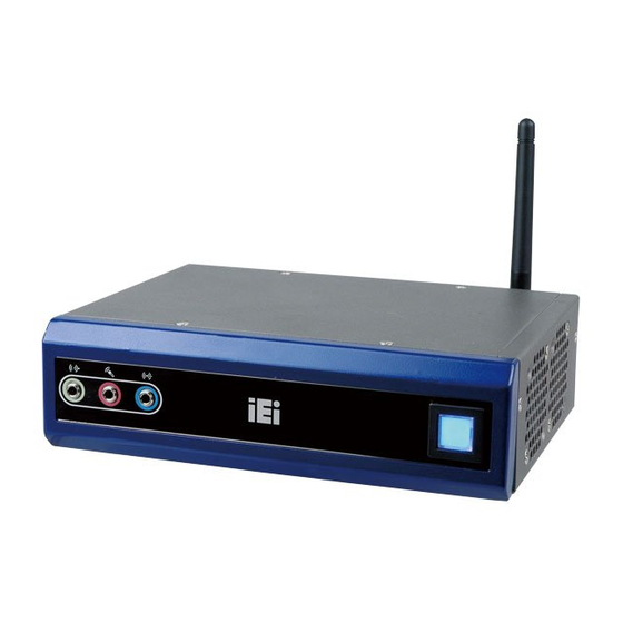
1.1 Overview Figure 1-1: ECN-581A-QM57 The ECN-581A-QM57 embedded system is a fanless system with two DVI ports for dual display. It is powered by the 32 nm Intel® Core™ i5 processor, uses the Intel® QM57 chipset and has 2.0 GB of DDR3 memory. The ECN-581A-QM57 supports a 2.5” SATA HDD with up to 3 Gb/s data transfer rate. -
Page 12: Technical Specifications
ECN-581A-QM57 Multimedia Box Intel® AMT 6.0 RoHS compliant 1.4 Technical Specifications The ECN-581A-QM57 technical specifications are listed in Table 1-2. System NANO-QM57A 2.4 GHz 32 nm Intel® Core™ i5 processor CPU and Models Intel® QM57 Chipset 2.0 GB of DDR3 SO-DIMM preinstalled... -
Page 13: Front Panel
EMC/Safety Table 1-2: Technical Specifications 1.5 Front Panel The front panel of the ECN-581A-QM57 contains one power button to power up the system and three audio jacks. The button is also a LED indicator that shows power and HDD status:... -
Page 14: Connector Panel
1.6 Connector Panel All external peripheral interface connectors are located on the front panel of the ECN-581A-QM57 . The peripheral interface connectors are shown in Figure 1-3. Figure 1-3: ECN-581A-QM57 Peripheral Connectors Connectors and buttons on the rear panel include the following. -
Page 15: Dimensions
ECN-581A-QM57 Multimedia Box 1.7 Dimensions The physical dimensions are shown below: Figure 1-4: Physical Dimensions (millimeters) Page 6... -
Page 16: Unpacking
ECN-581A-QM57 Multimedia Box Chapter Unpacking Page 7... -
Page 17: Anti-Static Precautions
Electrostatic discharge (ESD) can cause serious damage to electronic components, including the ECN-581A-QM57. Dry climates are especially susceptible to ESD. It is therefore critical that whenever the ECN-581A-QM57 or any other electrical component is handled, the following anti-static precautions are strictly adhered to. -
Page 18: Unpacking Checklist
If some of the components listed in the checklist below are missing, please do not proceed with the installation. Contact the IEI reseller or vendor you purchased the ECN-581A-QM57 from or contact an IEI sales representative directly. To contact an IEI sales representative, please send an email to sales@iei.com.tw. -
Page 19: Table 2-1: Package List Contents
ECN-581A-QM57 Multimedia Box Quantity Item and Part Number Image User manual and driver CD Table 2-1: Package List Contents Page 10... -
Page 20: Installation
ECN-581A-QM57 Multimedia Box Chapter Installation Page 11... -
Page 21: Installation Precautions
Electric shock and personal injury might occur if the rear panel of the ECN-581A-QM57 is opened while the power cord is still connected to an electrical outlet. -
Page 22: Figure 3-1: Retention Screws Removal
ECN-581A-QM57 Multimedia Box Figure 3-1: Retention Screws Removal Page 13... -
Page 23: Figure 3-2: Hdd Bracket Retention Screws (Inside)
Attach the HDD bracket to the HDD. Secure the HDD with the HDD bracket by Step 3: fastening four retention screws (Figure 3-3 Connect the SATA cable in the ECN-581A-QM57 to the HDD. Secure the SATA Step 4: cable with the HDD by fastening two round head screws (Figure 3-3... -
Page 24: Figure 3-3: Hdd Retention Screws
ECN-581A-QM57 Multimedia Box Figure 3-3: HDD Retention Screws Install the HDD bracket in the same position it was before. Step 5: Figure 3–4: HDD Installation Reinstall the front panel. Step 6: Page 15... -
Page 25: Mount The System
Step 7: S t e p 0 : 3.3 Mount the System The ECN-581A-QM57 supports wall mounting. The bottom panel of the ECN-581A-QM57 contains four screw holes for mounting (Figure 3-5) the system. Figure 3-5: Mounting Screw Holes 3.3.1 Mounting the System with Mounting Brackets To mount the embedded system onto a wall or some other surface using the two mounting brackets, please follow the steps below. -
Page 26: Figure 3-6: Mounting Bracket Retention Screws
ECN-581A-QM57 Multimedia Box Figure 3-6: Mounting Bracket Retention Screws Drill holes in the intended installation surface. Step 4: Align the mounting holes in the sides of the mounting brackets with the predrilled Step 5: holes in the mounting surface. NOTE: To have the best system heat dissipation, please make sure to face the I/O panel downward (Figure 3-6) when mounting the system. -
Page 27: Jumper Settings
OPEN a jumper means removing the plastic clip from a jumper. Before the ECN-581A-QM57 is installed in the system, the jumpers must be set in accordance with the desired configuration. The jumpers on the ECN-581A-QM57 are listed in T able 3-1. -
Page 28: At Auto Button Power Select Jumper Settings
ECN-581A-QM57 Multimedia Box Description Type Label AT Auto Button 2-pin header J_AUTOPWR1 AT/ATX Power Mode 3-pin header J_ATXCTL1 Setting Clear CMOS 3-pin header J_CMOS1 ME RTC Register 3-pin header ME_RTC1 ME RTC Security Override 2-pin header Table 3-1: Jumpers 3.4.1 AT Auto Button Power Select Jumper Settings... -
Page 29: At/Atx Power Select Jumper Settings
ECN-581A-QM57 Multimedia Box 3.4.2 AT/ATX Power Select Jumper Settings Jumper Label: J_ATXCTL1 Jumper Type: 3-pin header (1x3) Jumper Settings: See Table 3-3 Jumper Location: See Figure 3-9 The AT/ATX Power Select jumper specifies the systems power mode as AT or ATX. -
Page 30: Me Rtc Register Jumper
ECN-581A-QM57 Multimedia Box If the ECN-581A-QM57 fails to boot due to improper BIOS settings, the clear CMOS jumper clears the CMOS data and resets the system BIOS information. To do this, use the jumper cap to close pins 2 and 3 for a few seconds then reinstall the jumper clip back to pins 1 and 2. -
Page 31: Me Rtc Flash Security Override Jumper
ECN-581A-QM57 Multimedia Box The ME RTC Register jumper saves or clears the ME RTC registers. The ME RTC Register jumper settings are shown in Table 3-4. Setting Description Save ME RTC registers Short 1-2 Default (normal operation) Short 2-3 Clear ME RTC registers... -
Page 32: External Peripheral Interface Connectors
VGA monitor Wireless antenna To install these devices, connect the corresponding cable connector from the actual device to the corresponding ECN-581A-QM57 external peripheral interface connector making sure the pins are properly aligned. Figure 3-13: Peripheral Connectors (Front Panel) Page 23... -
Page 33: Audio Connector
Figure 3-14: Peripheral Connectors (Rear) 3.5.1 Audio Connector The audio jacks on the front panel enable the ECN-581A-QM57 to be connected to a stereo sound setup. To install the audio devices, follow the steps below. Identify the audio plugs. The plugs on your home theater system or speakers Step 1: may not match the colors on the rear panel. -
Page 34: Dvi Display Device Connection
The ECN-581A-QM57 has one female DVI-I connector and one female DVI-D connector on the external peripheral interface panel. The DVI connectors are connected to digital display devices. To connect a digital display device to the ECN-581A-QM57, please follow the instructions below. -
Page 35: Lan Connection (Single Connector)
Locate the RJ-45 connectors. The location of the LAN connector is shown in Step 1: Chapter 4. Align the connectors. Align the RJ-45 connector on the LAN cable with one of Step 2: the RJ-45 connectors on the ECN-581A-QM57. See Figure 3-17. Page 26... -
Page 36: Serial Device Connection
RJ-45 connector into the on-board RJ-45 connector. Step 0: 3.5.4 Serial Device Connection The ECN-581A-QM57 has two female DB-9 connectors on the external peripheral interface panel for connecting to serial devices. Follow the steps below to connect a serial device to the ECN-581A-QM57. -
Page 37: Usb Connection (Dual Connector)
ECN-581A-QM57 Multimedia Box Figure 3-18: Serial Device Connector Secure the connector. Secure the serial device connector to the external Step 3: interface by tightening the two retention screws on either side of the connector. Step 0: 3.5.5 USB Connection (Dual Connector) The external USB Series "A"... -
Page 38: Vga Monitor Connection
Figure 3-19: USB Connector 3.5.6 VGA Monitor Connection The ECN-581A-QM57 is shipped with a DVI-I (male) to VGA adapter (female DB-15 connector). The DB-15 connector is connected to a CRT or VGA monitor. To connect a monitor to the ECN-581A-QM57, please follow the instructions below. -
Page 39: Figure 3-20: Vga Connector
ECN-581A-QM57 Multimedia Box Align the VGA connector. Align the male DB-15 connector on the VGA screen Step 7: cable with the female DB-15 connector on the external peripheral interface. Insert the VGA connector. Once the connectors are properly aligned, insert the... -
Page 40: Bios
ECN-581A-QM57 Multimedia Box Chapter BIOS Page 31... -
Page 41: Introduction
ECN-581A-QM57 Multimedia Box 4.1 Introduction The BIOS is programmed onto the BIOS chip. The BIOS setup program allows changes to certain system settings. This chapter outlines the options that can be changed. 4.1.1 Starting Setup The AMI BIOS is activated when the computer is turned on. The setup program can be activated in one of two ways. -
Page 42: Getting Help
ECN-581A-QM57 Multimedia Box Function F4 key Save all the CMOS changes Table 4-1: BIOS Navigation Keys 4.1.3 Getting Help When F1 is pressed a small help window describing the appropriate keys to use and the possible selections for the highlighted item appears. To exit the Help Window press E the F1 key again. -
Page 43: Main
ECN-581A-QM57 Multimedia Box 4.2 Main The Main BIOS menu (BIOS Menu 1) appears when the BIOS Setup program is entered. The Main menu gives an overview of the basic system information. Aptio Setup Utility – Copyright (C) 2009 American Megatrends, Inc. -
Page 44: Advanced
ECN-581A-QM57 Multimedia Box System Date [xx/xx/xx] Use the System Date option to set the system date. Manually enter the day, month and year. System Time [xx:xx:xx] Use the System Time option to set the system time. Manually enter the hours, minutes and seconds. -
Page 45: Acpi Configuration
ECN-581A-QM57 Multimedia Box 4.3.1 ACPI Configuration The ACPI Configuration menu (BIOS Menu 3) configures the Advanced Configuration and Power Interface (ACPI) options. Aptio Setup Utility – Copyright (C) 2009 American Megatrends, Inc. Advanced ACPI Sleep State [S1 (CPU Stop Clo…)]... -
Page 46: Cpu Configuration
ECN-581A-QM57 Multimedia Box 4.3.2 CPU Configuration Use the CPU Configuration menu (BIOS Menu 4) to view detailed CPU specifications and configure the CPU. Aptio Setup Utility – Copyright (C) 2009 American Megatrends, Inc. Advanced CPU Configuration Processor Type Intel(R) Core(TM) i5 CPU... -
Page 47: Sata Configuration
ECN-581A-QM57 Multimedia Box 4.3.3 SATA Configuration Use the SATA Configuration menu (BIOS Menu 5) to change and/or set the configuration of the SATA devices installed in the system. Aptio Setup Utility – Copyright (C) 2009 American Megatrends, Inc. Advanced SATA Configuration (1) IDE Mode. -
Page 48: Usb Configuration
ECN-581A-QM57 Multimedia Box Configures the Serial-ATA controller to be in enhanced Enhanced EFAULT mode. In this mode, IDE channels and SATA channels are separated. Some legacy OS do not support this mode. Configures the Serial-ATA controller to be in compatible Compatible mode. - Page 49 ECN-581A-QM57 Multimedia Box All USB Devices [Enabled] Use the All USB Devices option to enable the USB devices. All USB devices are disabled. Disabled All USB devices are enabled. Enabled EFAULT Legacy USB Support [Enabled] Use the Legacy USB Support BIOS option to enable USB mouse and USB keyboard support.
-
Page 50: Super Io Configuration
ECN-581A-QM57 Multimedia Box 4.3.5 Super IO Configuration Use the Super IO Configuration menu (BIOS Menu 7) to set or change the configurations for the FDD controllers, parallel ports and serial ports. Aptio Setup Utility – Copyright (C) 2009 American Megatrends, Inc. - Page 51 ECN-581A-QM57 Multimedia Box 4.3.5.1.1 Serial Port 0 Configuration Serial Port [Enabled] Use the Serial Port option to enable or disable the serial port. Disable the serial port Disabled Enable the serial port Enabled EFAULT Change Settings [Auto] Use the Change Settings option to change the serial port IO port address and interrupt address.
- Page 52 ECN-581A-QM57 Multimedia Box 4.3.5.1.2 Serial Port 1 Configuration Serial Port [Enabled] Use the Serial Port option to enable or disable the serial port. Disable the serial port Disabled Enable the serial port Enabled EFAULT Change Settings [Auto] Use the Change Settings option to change the serial port IO port address and interrupt address.
-
Page 53: H/W Monitor
ECN-581A-QM57 Multimedia Box 4.3.6 H/W Monitor The H/W Monitor menu (BIOS Menu 9) shows the operating temperature, fan speeds and system voltages. Aptio Setup Utility – Copyright (C) 2009 American Megatrends, Inc. Advanced PC Health Status > Smart Fan Mode Configuration... - Page 54 ECN-581A-QM57 Multimedia Box Aptio Setup Utility – Copyright (C) 2009 American Megatrends, Inc. Advanced Smart Fan Mode Configuration CPU Fan Mode Select > CPU Fan Mode [Auto RPM Mode] First Boundary Temp Second Boundary Temp Third Boundary Temp Fourth Boundary Temp...
- Page 55 ECN-581A-QM57 Multimedia Box The fan adjusts its speed using these settings by Auto Duty Cycle Duty Cycle: Mode First Boundary Temperature Second Boundary Temperature Third Boundary Temperature Fourth Boundary Temperature Segment 1 Speed Count Segment 2 Speed Count Segment 3 Speed Count...
- Page 56 ECN-581A-QM57 Multimedia Box Minimum Value: 1°C Maximum Value: 128°C Second Boundary Temperature [050] WARNING: CPU failure can result if this value is set too high When the fan is off, it will only start when the temperature exceeds this setting.
- Page 57 ECN-581A-QM57 Multimedia Box Segment 1 Speed Count [100] This value is always full speed and corresponds to the First Boundary Temperature. This speed should be higher than Segment 2. Minimum Value: 1% Maximum Value: 100% Segment 2 Speed Count [085] This value is always full speed and corresponds to the Boundary Temperature.
-
Page 58: Amt Configuration
ECN-581A-QM57 Multimedia Box Starting Full Speed Count This value is the starting speed of the CPU fan. Minimum Value: 1000 RPM Maximum Value: 15000 RPM PC Health Status The following system parameters and values are shown. The system parameters that are... -
Page 59: Serial Port Console Redirection
ECN-581A-QM57 Multimedia Box Aptio Setup Utility – Copyright (C) 2009 American Megatrends, Inc. Advanced [Enabled] AMT Help Unconfigure AMT/ME [Disabled] --------------------- : Select Screen ↑ ↓: Select Item Enter Select General Help Previous Values Optimized Defaults Save Exit Version 2.00.1201. Copyright (C) 2009 American Megatrends, Inc. -
Page 60: Console Redirection Settings
ECN-581A-QM57 Multimedia Box Aptio Setup Utility – Copyright (C) 2009 American Megatrends, Inc. Advanced COM0 The settings specify how Console Redirection [Enabled] the host computer and the > Console Redirection Settings remote computer (which the user is using) will COM1 exchange data. -
Page 61: Figure 1-1: Ecn-581A-Qm57
ECN-581A-QM57 Multimedia Box Aptio Setup Utility – Copyright (C) 2009 American Megatrends, Inc. Advanced COM0 Emulation: ANSI: Console Redirection Settings Extended ASCII char set. VT100: ASCII char set. Terminal Type [VT-UTF8] VT100+: Extends VT100 to Bits per second [115200] support color, function Data Bits keys, etc. -
Page 62: Chipset
ECN-581A-QM57 Multimedia Box The transmission speed is 115200 115200 EFAULT 4.4 Chipset Use the Chipset menu (BIOS Menu 14) to access the Northbridge and Southbridge configuration menus WARNING! Setting the wrong values for the Chipset BIOS selections in the Chipset BIOS menu may cause the system to malfunction. -
Page 63: Northbridge Configuration
ECN-581A-QM57 Multimedia Box 4.4.1 Northbridge Configuration Use the Northbridge Chipset Configuration menu (BIOS Menu 15) to configure the Northbridge chipset. Aptio Setup Utility – Copyright (C) 2009 American Megatrends, Inc. Chipset Memory Information Select which graphics controller to use as the... -
Page 64: Southbridge Configuration
ECN-581A-QM57 Multimedia Box IGD Memory [32 MB] Use the IGD Memory option to specify the amount of system memory that can be used by the Internal graphics device. Disable 32 MB of memory used by internal graphics device 32 MB... - Page 65 ECN-581A-QM57 Multimedia Box The system turns on Power On EFAULT The system returns to its previous state. If it was on, it Last State turns itself on. If it was off, it remains off. Azalia HD Audio [Enabled] Use the Azalia HD Audio option to enable or disable the High Definition Audio controller.
-
Page 66: Integrated Graphics
ECN-581A-QM57 Multimedia Box 4.4.3 Integrated Graphics Use the Integrated Graphics menu to configure the video device connected to the system. Aptio Setup Utility – Copyright (C) 2009 American Megatrends, Inc. Chipset Intel IGD SWSCI OpRegion Configuration Select the DVMT/FIXED Mode Memory size used by... -
Page 67: Boot
ECN-581A-QM57 Multimedia Box EFP1 CRT + CRT1 CRT + EFP1 4.5 Boot Use the Boot menu (BIOS Menu 18) to configure system boot options. Aptio Setup Utility – Copyright (C) 2009 American Megatrends, Inc. Main Advanced Chipset Boot Security Save & Exit... - Page 68 ECN-581A-QM57 Multimedia Box Does not enable the keyboard Number Lock automatically. To use the 10-keys on the keyboard, press the Number Lock key located on the upper left-hand corner of the 10-key pad. The Number Lock LED on the keyboard lights up when the Number Lock is engaged.
-
Page 69: Security
ECN-581A-QM57 Multimedia Box 4.6 Security Use the Security menu (BIOS Menu 19) to set system and user passwords. Aptio Setup Utility – Copyright (C) 2009 American Megatrends, Inc. Main Advanced Chipset Boot Security Save & Exit Password Description Set Setup Administrator Password If ONLY the Administrator’s password is set,... -
Page 70: Exit
ECN-581A-QM57 Multimedia Box 4.7 Exit Use the Exit menu (BIOS Menu 20) to load default BIOS values, optimal failsafe values and to save configuration changes. Aptio Setup Utility – Copyright (C) 2009 American Megatrends, Inc. Main Advanced Chipset Boot Security Save &... - Page 71 ECN-581A-QM57 Multimedia Box Discard Changes Use the Discard Changes option to discard the changes and remain in the BIOS configuration setup program. Restore Defaults Use the Restore Defaults option to load the optimal default values for each of the parameters on the Setup menus. F3 key can be used for this operation.
-
Page 72: A Intel® Amt Configuration
ECN-581A-QM57 Multimedia Box Appendix Intel® AMT Configuration Page 63... -
Page 73: Intel ® Amt Setup Procedure
® A.1 Intel AMT Setup Procedure The ECN-581A-QM57 is featured with the Intel® Active Management Technology (AMT) 6.0. To enable the Intel® AMT function, follow the steps below. Make sure the DIMM1 socket is installed with one DDR3 SO-DIMM. Step 1: Connect an Ethernet cable to the RJ-45 connector labeled LAN2_USB2. -
Page 74: Figure A-2: Intel® Current Me Password
ECN-581A-QM57 Multimedia Box Enter the Intel® ME password as it requires (Figure B-7). Enter the Intel® Step 2: default password: admin. Intel(R) Management Engine BIOS Extension v6.0.3.0019/Intel(R) ME v6.0.30.1203 Copyright (C) 2003-09 Intel Corporation. All Right Reserved. [MAIN MENU] Intel(R) ME General Settings... -
Page 75: Figure A-3: Intel® Me New Password
ECN-581A-QM57 Multimedia Box Intel(R) Management Engine BIOS Extension v6.0.3.0019/Intel(R) ME v6.0.30.1203 Copyright (C) 2003-09 Intel Corporation. All Right Reserved. [MAIN MENU] Intel(R) ME General Settings Intel(R) AMT Configuration Exit [ESC]=Exit ]=Select [ENTER]=Access Intel(R) ME New Password Figure A-3: Intel® ME New Password Select Intel®... -
Page 76: Figure A-5: Select Kvm Configuration
ECN-581A-QM57 Multimedia Box Select KVM Configuration and press Enter. (Figure B-13) Step 6: Intel(R) Management Engine BIOS Extension v6.0.3.0019/Intel(R) ME v6.0.30.1203 Copyright (C) 2003-09 Intel Corporation. All Right Reserved. [Intel(R) AMT CONFIGURATION] Manageability Feature Selection SOL/IDER KVM Configuration Previous Menu... -
Page 77: Figure A-7: Kvm User Opt-In
ECN-581A-QM57 Multimedia Box Two options are shown as in Figure B-18. Choose User Consent is not Step 8: required for KVM session which means no password is required for using iAMT function. Then press Enter. Intel(R) Management Engine BIOS Extension v6.0.3.0019/Intel(R) ME v6.0.30.1203 Copyright (C) 2003-09 Intel Corporation. -
Page 78: Iei Easy Manager Application
ECN-581A-QM57 Multimedia Box A.3 IEI Easy Manager Application IEI Easy Manager (iEZMan) application program allows a remote user, such as a support person, to remotely control and perform administrative tasks through a graphical user interface in Windows. The functions of the iEZMan application include... -
Page 79: B One Key Recovery
ECN-581A-QM57 Multimedia Box Appendix One Key Recovery Page 70... -
Page 80: One Key Recovery Introduction
ECN-581A-QM57 Multimedia Box B.1 One Key Recovery Introduction The IEI one key recovery is an easy-to-use front end for the Norton Ghost system backup and recovery tool. The one key recovery provides quick and easy shortcuts for creating a backup and reverting to that backup or for reverting to the factory default settings. - Page 81 ECN-581A-QM57 Multimedia Box Windows 7 Windows CE 5.0 Windows CE 6.0 Windows XP Embedded Linux Fedora Core 12 (Constantine) Fedora Core 11 (Leonidas) Fedora Core 10 (Cambridge) Fedora Core 8 (Werewolf) Fedora Core 7 (Moonshine) RedHat RHEL-5.4 RedHat 9 (Ghirke) Ubuntu 8.10 (Intrepid)
-
Page 82: Setup Procedure For Windows
ECN-581A-QM57 Multimedia Box NOTE: The recovery CD can only be used with IEI products. The software will fail to run and a warning message will appear when used on non-IEI hardware. B.2 Setup Procedure for Windows Prior to using the recovery tool to backup or restore system, a few setup procedures are required. -
Page 83: Hardware And Bios Setup
B.2.1 Hardware and BIOS Setup Make sure the system is powered off and unplugged. Step 1: Install a hard driver or SSD in the ECN-581A-QM57. An unformatted and Step 2: unpartitioned disk is recommended. Connect an optical disk drive to the ECN-581A-QM57 and insert the recovery Step 3: Turn on the system. -
Page 84: Figure B-1: Recovery Tool Setup Menu
ECN-581A-QM57 Multimedia Box Figure B-1: Recovery Tool Setup Menu Press <5> then <Enter>. Step 5: Figure B-2: Command Mode The command prompt window appears. Type the following commands (marked Step 6: in red) to create two partitions. One is for the OS installation; the other is for saving recovery files and images which will be an invisible partition. -
Page 85: Figure B-3: Partition Creation Commands
ECN-581A-QM57 Multimedia Box Figure B-3: Partition Creation Commands Page 76... -
Page 86: Install Operating System, Drivers And Applications
ECN-581A-QM57 Multimedia Box NOTE: Use the following commands to check if the partitions were created successfully. Press any key to exit the recovery tool and automatically reboot the system. Step 7: Please continue to the following procedure: Build-up Recovery Partition.S t e p 0 : B.2.3 Install Operating System, Drivers and Applications... -
Page 87: Figure B-4: System Configuration For Windows
ECN-581A-QM57 Multimedia Box Start the system. Step 2: Press any key to boot from the recovery CD. It will take a while to launch the Step 3: recovery tool. Please be patient. When the recovery tool setup menu appears, press <2> then <Enter>. -
Page 88: Create Factory Default Image
ECN-581A-QM57 Multimedia Box After completing the system configuration, press any key in the following window Step 6: to reboot the system. Figure B-6: Press any key to continue Eject the recovery CD. Step 7: S t e p 0 : B.2.5 Create Factory Default Image... -
Page 89: Figure B-8: Recovery Tool Menu
ECN-581A-QM57 Multimedia Box Figure B-8: Recovery Tool Menu The About Symantec Ghost window appears. Click OK button to continue. Step 3: Figure B-9: About Symantec Ghost Window Use mouse to navigate to the option shown below (Figure B-10). Step 4:... -
Page 90: Figure B-10: Symantec Ghost Path
ECN-581A-QM57 Multimedia Box Figure B-10: Symantec Ghost Path Select the local source drive as shown in Figure B-11. Then click OK. Step 5: Figure B-11: Select a Local Source Drive Select a source partition from basic drive as shown in Figure B-12. Then click... -
Page 91: Figure B-13: File Name To Copy Image To
ECN-581A-QM57 Multimedia Box Select 1.2: [Recovery] NTFS drive and enter a file name called Step 7: (Figure B-13). Click Save. The factory default image will then be saved in the selected recovery drive and named IEI.GHO. WARNING: The file name of the factory default image must be iei.GHO. -
Page 92: Figure B-14: Compress Image
ECN-581A-QM57 Multimedia Box When the Compress Image screen in Figure B-14 prompts, click High to make Step 8: the image file smaller. Figure B-14: Compress Image The Proceed with partition image creation window appears, click Yes to Step 9: continue. -
Page 93: Setup Procedure For Linux
ECN-581A-QM57 Multimedia Box When the image creation completes, a screen prompts as shown in Figure B-18. Step 11: Click Continue and close the Ghost window to exit the program. Figure B-17: Image Creation Complete The recovery tool main menu window is shown as below. Press any key to Step 12: reboot the system. -
Page 94: Figure B-19: Partitions For Linux
ECN-581A-QM57 Multimedia Box NOTE: If the Linux OS is not installed with GRUB (v0.97 or earlier) and Ext3, the Symantec Ghost may not function properly. While installing Linux OS, please create two partitions: Partition 1: / Partition 2: SWAP NOTE: Please reserve enough space for partition 3 for saving recovery images. -
Page 95: Figure B-20: System Configuration For Linux
ECN-581A-QM57 Multimedia Box system32>format N: /fs:ntfs /q /v:Recovery /y system32>exit Build-up recovery partition. Press any key to boot from the recovery CD. It will Step 4: take a while to launch the recovery tool. Please be patient. When the recovery tool setup menu appears, type <3>... -
Page 96: Recovery Tool Functions
ECN-581A-QM57 Multimedia Box The recovery tool menu appears. (Figure B-22) Step 7: Figure B-22: Recovery Tool Menu Create a factory default image. Follow described in Section Step 8: Step 2 Step 12 B.2.5 to create a factory default image. S t e p 8 : B.4 Recovery Tool Functions... -
Page 97: Figure B-23: Recovery Tool Main Menu
ECN-581A-QM57 Multimedia Box Figure B-23: Recovery Tool Main Menu The recovery tool has several functions including: 1. Factory Restore: Restore the factory default image (iei.GHO) created in Section B.2.5. 2. Backup system: Create a system backup image (iei_user.GHO) which will be saved in the hidden partition. -
Page 98: Factory Restore
ECN-581A-QM57 Multimedia Box B.4.1 Factory Restore To restore the factory default image, please follow the steps below. Type <1> and press <Enter> in the main menu. Step 9: The Symantec Ghost window appears and starts to restore the factory default. A Step 10: factory default image called iei.GHO is created in the hidden Recovery partition. -
Page 99: Backup System
ECN-581A-QM57 Multimedia Box B.4.2 Backup System To backup the system, please follow the steps below. Type <2> and press <Enter> in the main menu. Step 12: The Symantec Ghost window appears and starts to backup the system. A Step 13: backup image called iei_user.GHO is created in the hidden Recovery partition. -
Page 100: Restore Your Last Backup
ECN-581A-QM57 Multimedia Box B.4.3 Restore Your Last Backup To restore the last system backup, please follow the steps below. Type <3> and press <Enter> in the main menu. Step 15: The Symantec Ghost window appears and starts to restore the last backup Step 16: image (iei_user.GHO). -
Page 101: Manual
ECN-581A-QM57 Multimedia Box B.4.4 Manual To restore the last system backup, please follow the steps below. Type <4> and press <Enter> in the main menu. Step 18: The Symantec Ghost window appears. Use the Ghost program to backup or Step 19: recover the system manually. -
Page 102: C Safety Precautions
ECN-581A-QM57 Multimedia Box Appendix Safety Precautions Page 93... -
Page 103: Safety Precautions
ECN-581A-QM57 Multimedia Box C.1 Safety Precautions WARNING: The precautions outlined in this appendix should be strictly followed. Failure to follow these precautions may result in permanent damage to the ECN-581A-QM57. Please follow the safety precautions outlined in the sections that follow: C.1.1 General Safety Precautions... -
Page 104: Anti-Static Precautions
When maintaining or cleaning the ECN-581A-QM57, please follow the guidelines below. C.2.1 Maintenance and Cleaning Prior to cleaning any part or component of the ECN-581A-QM57, please read the details below. The interior of the ECN-581A-QM57 does not require cleaning. Keep fluids away from the ECN-581A-QM57 interior. -
Page 105: Cleaning Tools
In such case, the product will be explicitly mentioned in the cleaning tips. Below is a list of items to use when cleaning the ECN-581A-QM57. C loth – Although paper towels or tissues can be used, a soft, clean piece of cloth is recommended when cleaning the ECN-581A-QM57. -
Page 106: D Hazardous Materials Disclosure
ECN-581A-QM57 Multimedia Box Appendix Hazardous Materials Disclosure Page 97... -
Page 107: Hazardous Materials Disclosure Table For Ipb Products Certified As Rohs Compliant Under 2002/95/Ec Without Mercury
ECN-581A-QM57 Multimedia Box D.1 Hazardous Materials Disclosure Table for IPB Products Certified as RoHS Compliant Under 2002/95/EC Without Mercury The details provided in this appendix are to ensure that the product is compliant with the Peoples Republic of China (China) RoHS standards. The table below acknowledges the presences of small quantities of certain materials in the product, and is applicable to China RoHS only. - Page 108 ECN-581A-QM57 Multimedia Box Part Name Toxic or Hazardous Substances and Elements Lead Mercury Cadmium Hexavalent Polybrominated Polybrominated Biphenyls Diphenyl (Pb) (Hg) (Cd) Chromium (CR(VI)) (PBB) Ethers (PBDE) Housing Display Printed Circuit Board Metal Fasteners Cable Assembly Fan Assembly Power Supply...
- Page 109 ECN-581A-QM57 Multimedia Box 此附件旨在确保本产品符合中国 RoHS 标准。以下表格标示此产品中某有毒物质的含量符 合中国 RoHS 标准规定的限量要求。 本产品上会附有”环境友好使用期限”的标签,此期限是估算这些物质”不会有泄漏或突变”的 年限。本产品可能包含有较短的环境友好使用期限的可替换元件,像是电池或灯管,这些元 件将会单独标示出来。 部件名称 有毒有害物质或元素 铅 汞 镉 六价铬 多溴联苯 多溴二苯 醚 (Pb) (Hg) (Cd) (CR(VI)) (PBB) (PBDE) 壳体 显示 印刷电路板 金属螺帽 电缆组装 风扇组装 电力供应组装 电池 O: 表示该有毒有害物质在该部件所有物质材料中的含量均在 SJ/T11363-2006 标准规定的限量要求以下。 X: 表示该有毒有害物质至少在该部件的某一均质材料中的含量超出 SJ/T11363-2006 标准规定的限量要求。...
Need help?
Do you have a question about the ECN-581A-QM57 and is the answer not in the manual?
Questions and answers