Sign In
Upload
Manuals
Brands
IEI Technology Manuals
Desktop
DRPC-100
IEI Technology DRPC-100 Manuals
Manuals and User Guides for IEI Technology DRPC-100. We have
1
IEI Technology DRPC-100 manual available for free PDF download: User Manual
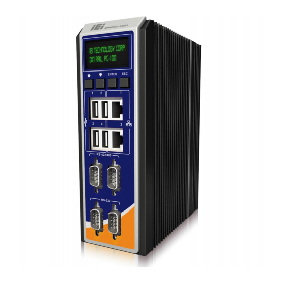
IEI Technology DRPC-100 User Manual (160 pages)
Fanless Embedded System with Intel Atom N2800 CPU, DIN Rail Mounting Support, OLED Display or LED Indicators, Dual GbE, USB, DIO, CAN-bus, Serial Ports, 9V~28V DC Power Input, RoHS Compliant
Brand:
IEI Technology
| Category:
Desktop
| Size: 5 MB
Table of Contents
User Manual
1
Table of Contents
4
1 Introduction
15
Figure 1-1: DRPC-100
16
Figure 1-2: DRPC-100 Front Panel
18
Figure 1-3: DRPC-100 Top Panel
19
Figure 1-4: DRPC-100-CV-LED LED Indicators
20
LED Indicators (DRPC-100-CV-LED Only)
20
Table 1-2: DRPC-100-CV-LED LED Definitions
20
Programmable OLED Display (DRPC-100-CV-OLED Only)
21
Technical Specifications
21
Table 1-3: Technical Specifications
22
Dimensions
23
Top Panel
19
Model Variations
16
Overview
16
Table 1-1: DRPC-100 Model Variations
16
Features
17
Connector Panel
18
Front Panel
18
Figure 1-5: Physical Dimensions (Millimeters)
23
2 Unpacking
24
Anti-Static Precautions
25
Unpacking Precautions
25
Unpacking Checklist
26
3 Installation
28
Installation Precautions
29
High Surface Temperature
29
Cf Card Installation
30
Figure 3-1: CF Card Slot Cover
30
Figure 3-2: CF Card Installation
31
Figure 3-6: Hex Nuts on the Top Panel
33
Figure 3-7: Retention Screws on the Motherboard
33
Figure 3-8: Pcie Mini Slot Location
34
Figure 3-9: Inserting the Pcie Mini Card into the Socket
34
Figure 3-10: Securing the Pcie Mini Card
35
Access the Jumpers
36
Clear CMOS Jumper
36
Table 3-1: Jumpers
36
Table 3-2: Clear CMOS Jumper Settings
36
At/Atx Mode Selection
37
Figure 3-11: Clear CMOS Jumper Location
37
Figure 3-12: AT/ATX Switch Location
37
Figure 3-13: DIN Rail Mounting Bracket
38
Figure 3-14: Attach the DIN Rail to the Mounting Bracket
38
Mounting the System
38
CAN-Bus Terminal Block
39
External Peripheral Interface Connectors
39
Figure 3-15: Mounting the DIN Rail
39
Digital Input/Output Terminal Block
40
Figure 3-16: CAN-Bus Terminal Block Pinout Location
40
Table 3-3: CAN-Bus Terminal Block Pinouts
40
Table 3-4: DIO Terminal Block Pinouts
40
Figure 3-17: DIO Terminal Block Pinout Location
41
LAN Connectors
41
Jumper Settings
35
Figure 3-3: Replacing the CF Card Slot Cover
31
Motherboard Removal
31
Figure 3-5: Hex Nuts on the Front Panel
32
Figure 3-4: Retention Screws
32
Msata Ssd Installation
33
Figure 3-19: RJ-45 Ethernet Connector
42
Figure 3-20: 3-Pin Power Terminal Block Pinout Location
43
Figure 3-21: RS-232 Serial Device Connector
44
Serial Port Connectors
44
Figure 3-23: RS-422/485 Serial Device Connector
46
Figure 3-24: RS-422/485Serial Port Pinout Location
46
Figure 3-25: USB Device Connection
47
Table 3-10: USB Port Pinouts
48
VGA Connector
48
Figure 3-26: VGA Connector
49
Figure 3-27: VGA Connector
49
Table 3-11: VGA Connector Pinouts
49
Driver Installation
50
Table 3-9: RS-422/485 Serial Port Pinouts
46
USB Connectors
47
Figure 3-18: LAN Connection
42
Table 3-5: LAN Pinouts
42
Power Input, 3-Pin Terminal Block
43
Table 3-7: 3-Pin Power Terminal Block Pinouts
43
Figure 3-22:RS-232 Serial Port Pinout Location
45
RS-422/485 Serial Port Connectors
45
Table 3-8: RS-232 Serial Port Pinouts
45
Table 3-6: RJ-45 Ethernet Connector Leds
43
4 System Maintenance
51
System Maintenance Introduction
52
Motherboard Replacement
52
So-DIMM Replacement
53
Figure 4-1: SO-DIMM Module Location
53
Figure 4-2: SO-DIMM Module Installation
54
5 Bios
55
Introduction
56
Starting Setup
56
Using Setup
56
Getting Help
57
Unable to Reboot after Configuration Changes
57
BIOS Menu Bar
57
Table 5-1: BIOS Navigation Keys
57
Main
58
Advanced
59
ACPI Settings
60
CPU Configuration
61
IDE Configuration
62
USB Configuration
63
F81866 Super IO Configuration
64
Serial Port N Configuration
65
F81866 H/W Monitor
71
Smart Fan Mode Configuration
73
Serial Port Console Redirection
74
Chipset
76
Host Bridge Configuration
77
Intel IGD Configuration
77
South Bridge Configuration
78
Boot
79
Security
81
Save & Exit
82
6 Programmable Oled Display (Drpc-100-CV-Oled Only)
84
Oled Image Editor
85
OLED Image Editor Installation
85
Overview
85
Figure 6-2: Select Installation Folder
86
Figure 6-3: Confirm Installation
87
Figure 6-5: OLED Image Editor
88
Figure 6-6: Function List
88
Figure 6-7: OLED Control
89
Figure 6-8: OLED Erase Page
90
OLED Erase Page
90
Drpc100 Demo Program
91
Figure 6-9: DR100 Demo Program Main Menu
91
Dialog Menu
92
Figure 6-10: Dialog Menu
92
Figure 6-11: LCD Menu
93
LCD Menu
93
DEMO Menu
94
OLED Control
89
Figure 6-1: OLED Image Editor Setup Wizard
86
Figure 6-4: Installation Complete
87
Function List
88
Launching the OLED Image Editor
88
Figure 6-12: DEMO Menu
94
7 Interface Connectors
95
Figure 7-1: Main Board Layout Diagram (Front Side)
96
Table 7-2: Battery Connector (CN1) Pinouts
97
Table 7-1: Peripheral Interface Connectors
97
Table 7-3: Burn in CAN-Bus Firmware Connector (CN4) Pinouts
98
Table 7-4: Burn in MCU Firmware (JP5) Pinouts
98
CPU Fan Connector (CPU_FAN1)
99
Table 7-5: Compactflash® Card Slot (CF1) Pinouts
99
Table 7-6: CPU Fan Connector (CPU_FAN1) Pinouts
99
Indicator Connector (F_PANEL1)
100
OLED/LED Signal Connector (OLED1)
100
Pcie Mini Card Slot (M_PCIE1)
100
Table 7-7: Indicator Connector (F_PANEL1) Pinouts
100
Table 7-8: OLED/LED Signal Connector (OLED1) Pinouts
100
SATA 3Gb/S Connectors(SATA1)
101
Table 7-9: Pcie Mini Card Slot (M_PCIE1) Pinouts
101
External Interface Panel Connectors
102
SATA Power Connector (SATA_PWR1)
102
SPI Flash Connector (SPI1)
102
Burn in CAN-Bus Firmware Connector (CN4)
98
Burn in MCU Firmware Connector (JP5)
98
Compactflash® Card Slot (CF1)
98
Figure 7-2: Main Board Layout Diagram (Solder Side)
96
Peripheral Interface Connectors
96
Internal Peripheral Connectors
97
Battery Connector (CN1)
97
Table 7-10: SATA 3Gb/S Connector (SATA1) Pinouts
101
Table 7-11: SATA Power Connector (SATA_PWR1) Pinouts
102
Table 7-12: SPI Flash Connector (SPI1) Pinouts
102
Table 7-16: Power Input Terminal Block (DC_CN1) Pinouts
103
LAN Connectors (LAN/USB1, LAN/USB2)
104
RS-422/485 Serial Ports (COM3/4)
104
Serial Ports (COM1/2)
104
CAN-Bus Terminal Block (CAN1)
103
Digital I/O Terminal Block (J1)
103
Power Input Terminal Block (DC_CN1)
103
Table 7-15: Digital I/O Terminal Block (J1) Pinouts
103
Table 7-18: RS-232 Serial Port Pinouts
104
Table 7-17: RJ-45 LAN Connector Pinouts
104
Table 7-22: Jumpers
105
Table 7-21: VGA Connector (VGA1) Pinouts
105
Table 7-20: USB 2.0 Connectors (LAN/USB1, LAN/USB2) Pinouts
105
CAN-Bus 1 Long Wire Transmitting Jumper (JP3)
106
CAN-Bus 2 Long Wire Transmitting Jumper (JP4)
106
Clear CMOS Jumper (JP1)
106
Table 7-14: CAN-Bus Terminal Block (CAN1) Pinouts
103
Table 7-13: Rear Panel Connectors
103
Table 7-19: RS-422/485 Serial Port Pinouts
104
Jumper Settings
105
USB 2.0 Connectors (LAN/USB1, LAN/USB2)
105
VGA Connector (VGA1)
105
Table 7-23: Clear CMOS Jumper (JP1) Settings
106
Table 7-24: C CAN-Bus 1 Long Wire Transmitting Jumper (JP3) Settings
106
Table 7-25: C CAN-Bus 2 Long Wire Transmitting Jumper (JP4) Settings
106
A One Key Recovery
107
A.1 O Ne K Ey R Ecovery I Ntroduction
108
Figure A-1: IEI One Key Recovery Tool Menu
108
One Key Recovery Introduction
108
System Requirement
109
Supported Operating System
110
A.2 S Etup P Rocedure for W Indows
111
Create Partitions
112
Hardware and BIOS Setup
112
Setup Procedure for Windows
111
Figure A-3: Recovery Tool Setup Menu
113
Figure A-6: Launching the Recovery Tool
117
Figure A-8: Building the Recovery Partition
118
Figure A-7: Manual Recovery Environment for Windows
118
Create Factory Default Image
119
Figure A-2: Launching the Recovery Tool
113
Figure A-4: Command Mode
114
Figure A-5: Partition Creation Commands
115
Install Operating System, Drivers and Applications
116
Build-Up Recovery Partition
117
Figure A-10: Press F3 to Boot into Recovery Mode
119
Figure A-9: Press any Key to Continue
119
Figure A-11: Recovery Tool Menu
120
Figure A-12: about Symantec Ghost Window
120
Figure A-14: Select a Local Source Drive
121
Figure A-13: Symantec Ghost Path
121
Figure A-15: Select a Source Partition from Basic Drive
121
Figure A-16: File Name to Copy Image to
122
Figure A-19: Image Creation Process
123
Figure A-18: Image Creation Confirmation
123
Figure A-17: Compress Image
123
A.3 a Uto R Ecovery S Etup P Rocedure
124
Auto Recovery Setup Procedure
124
Figure A-20: Image Creation Complete
124
Figure A-22: Auto Recovery Utility
125
Figure A-23: Disable Automatically Restart
126
Figure A-24: Launching the Recovery Tool
127
Figure A-26: Building the Auto Recovery Partition
127
Figure A-27: Factory Default Image Confirmation
128
Figure A-28: Image Creation Complete
128
Figure A-29: Press any Key to Continue
128
Figure A-30: IEI Feature
129
Setup Procedure for Linux
129
Figure A-31: Partitions for Linux
130
Figure A-32: System Configuration for Linux
131
Figure A-33: Access Menu.lst in Linux (Text Mode)
131
Figure A-34: Recovery Tool Menu
132
Recovery Tool Functions
132
Figure A-35: Recovery Tool Main Menu
133
Factory Restore
134
Figure A-36: Restore Factory Default
134
Figure A-37: Recovery Complete Window
134
Backup System
135
Figure A-38: Backup System
135
Figure A-39: System Backup Complete Window
135
Figure A-40: Restore Backup
136
Figure A-41: Restore System Backup Complete Window
136
Restore Your Last Backup
136
Figure A-42: Symantec Ghost Window
137
Manual
137
Restore Systems from a Linux Server through Lan
137
Configure DHCP Server Settings
138
Configure TFTP Settings
140
Configure One Key Recovery Server Settings
141
Start the DHCP, TFTP and HTTP
141
Create Shared Directory
142
Setup a Client System for Auto Recovery
143
Figure A-43: Disable Automatically Restart
144
A.7 O Ther I Nformation
146
Other Information
146
Using AHCI Mode or Ali M5283 / VIA VT6421A Controller
146
System Memory Requirement
148
A.5 R Ecovery T Ool F Unctions
132
Figure A-21: Press any Key to Continue
124
Figure A-25: Auto Recovery Environment for Windows
127
A.4 S Etup P Rocedure for L Inux
129
B Safety Precautions
149
Safety Precautions
150
General Safety Precautions
150
B.1 S Afety P Recautions
150
Anti-Static Precautions
151
Explanation of Graphical Symbols
151
Product Disposal
152
Maintenance and Cleaning Precautions
152
Maintenance and Cleaning
152
Cleaning Tools
153
C Digital I/O Interface
154
Introduction
155
Dio Connector Pinouts
155
C.1 I Ntroduction
155
Assembly Language Samples
156
Enable the DIO Input Function
156
Enable the DIO Output Function
156
C.3 a Ssembly L Anguage S Amples
156
D Hazardous Materials Disclosure
157
Hazardous Materials Disclosure Table for IPB Products Certified as Rohs Compliant under 2002/95/EC Without Mercury
158
D.1 H Azardous M Aterials D Isclosure T Able for Ipb P Roducts C Ertified as R O Hs C Ompliant U Nder 2002/95/Ec W Ithout M Ercury
158
Advertisement
Advertisement
Related Products
IEI Technology DRPC-120-BTi
IEI Technology DRPC-330-A7K Series
IEI Technology DRPC-120-BT
IEI Technology DRPC-120-BTi-E5-LED/2G
IEI Technology DRPC-120-BTi-E5-OLED/2G
IEI Technology DRPC-124-EHL Series
IEI Technology DRPC-124-EHL-JC-R10
IEI Technology DRPC-140-EHL Series
IEI Technology DRPC-100-CV-LED-R10
IEI Technology DRPC-100-CV-OLED-R10
IEI Technology Categories
Motherboard
Touch Panel
Computer Hardware
Single board computers
Desktop
More IEI Technology Manuals
Login
Sign In
OR
Sign in with Facebook
Sign in with Google
Upload manual
Upload from disk
Upload from URL