Table of Contents
Advertisement
Quick Links
Advertisement
Table of Contents
Troubleshooting

Related Manuals for IEI Technology HTB-100-HM170


Summary of Contents for IEI Technology HTB-100-HM170
-
Page 1: User Manual
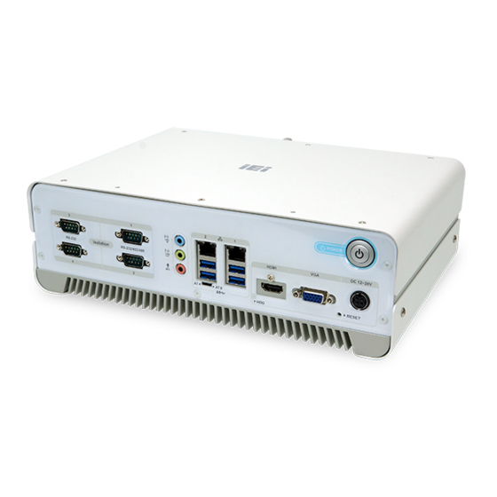
HTB-100-HM170 Medical Box PC HTB-100-HM170 Medical Box PC MODEL: MODEL: HTB-100-HM170 IEI Fanless Medical Box PC with Intel® Core™ i7-6822EQ / i5-6442EQ Processor, Isolated COM Ports, GbE LAN, HDMI, VGA, USB 3.0, Audio, RoHS Compliant, User Manual Page i Rev. 1.00 – October 2, 2017... - Page 2 HTB-100-HM170 Medical Box PC Revision Date Version Changes October 2, 2017 1.00 Initial release Page ii...
- Page 3 HTB-100-HM170 Medical Box PC Copyright COPYRIGHT NOTICE The information in this document is subject to change without prior notice in order to improve reliability, design and function and does not represent a commitment on the part of the manufacturer. In no event will the manufacturer be liable for direct, indirect, special, incidental, or consequential damages arising out of the use or inability to use the product or documentation, even if advised of the possibility of such damages.
-
Page 4: Manual Conventions
HTB-100-HM170 Medical Box PC Manual Conventions WARNING Warnings appear where overlooked details may cause damage to the equipment or result in personal injury. Warnings should be taken seriously. CAUTION Cautionary messages should be heeded to help reduce the chance of losing data or damaging the product. -
Page 5: Table Of Contents
HTB-100-HM170 Medical Box PC Table of Contents 1 INTRODUCTION......................1 1.1 O ........................2 VERVIEW 1.2 F ........................3 EATURES 1.3 M ....................3 ODEL ARIATIONS 1.4 E ....................3 XTERNAL VERVIEW 1.4.1 Front Panel ......................4 1.4.2 Rear Panel ......................4 1.5 T... - Page 6 HTB-100-HM170 Medical Box PC 3.11 C )............. 29 ABLE OVER NSTALLATION PTIONAL 3.12 AT/ATX M ..................31 ELECTION 3.13 P ..................31 OWER ROCEDURE 3.13.1 Installation Checklist ..................31 3.13.2 Power-on Procedure ..................32 3.14 C CMOS......................33 LEAR 3.15 D ...................
- Page 7 HTB-100-HM170 Medical Box PC 4.4.2.1 PCI Express Configuration ............... 70 4.4.2.2 HD Audio Configuration................71 4.5 S ......................... 72 ECURITY 4.6 B ........................73 4.7 S & E ......................75 5 TROUBLESHOOTING AND MAINTENANCE ............. 77 5.1 HTB-100-HM170 S ........... 78...
- Page 8 HTB-100-HM170 Medical Box PC 6.2.18 TPM Connector (CN1)................... 93 6.2.19 USB 2.0 Connector (USB1) ................94 6.2.20 VGA Power Connector (CN2)................ 94 6.3 E ............94 XTERNAL NTERFACE ANEL ONNECTORS 6.3.1 HDMI Connector (HDMI1) ................95 6.3.2 Ethernet and USB 3.0 Combo Connectors ............95 6.3.3 Power Input Jack (PWR1) ................
- Page 9 HTB-100-HM170 Medical Box PC List of Figures Figure 1-1: HTB-100-HM170 Series Medical Box PC..............2 Figure 1-2: Front Panel ........................4 Figure 1-3: Rear Panel........................4 Figure 1-4: Dimensions (mm) ......................7 Figure 3-1: Top Cover Retention Screws ...................16 Figure 3-2: HDD Bracket Retention Screws................17 Figure 3-3: Inserting the HDD......................17...
- Page 10 HTB-100-HM170 Medical Box PC Figure 5-2: SO-DIMM Location ....................81 Figure 5-3: SO-DIMM Installation ....................82 Figure 6-1: Jumper and Connector Locations................84 Page x...
- Page 11 HTB-100-HM170 Medical Box PC List of Tables Table 1-1: Model Variations ......................3 Table 1-2: Technical Specifications....................6 Table 2-1: Package List........................11 Table 3-1: RS-232 Serial Port (COM1) Pinouts ................24 Table 3-2: RS-232/422/485 Serial Port Pinouts ................25 Table 4-1: BIOS Navigation Keys ....................37 Table 6-1: Peripheral Interface Connectors ................86...
- Page 12 HTB-100-HM170 Medical Box PC Table 6-26: Power Input Jack (PWR1) Pinouts ................96 Table 6-27: USB 2.0 Connectors (USB3) Pinouts..............96 Table 6-28: VGA Connector (VGA1) Pinouts ................97 Page xii...
- Page 13 HTB-100-HM170 Medical Box PC List of BIOS Menus BIOS Menu 1: Main ........................38 BIOS Menu 2: Advanced ......................40 BIOS Menu 3: Trusted Computing ....................41 BIOS Menu 4: ACPI Settings .......................42 BIOS Menu 5: Super IO Configuration..................43 BIOS Menu 6: Serial Port n Configuration Menu...............43 BIOS Menu 7: iWDD H/W Monitor ....................50...
-
Page 15: Introduction
HTB-100-HM170 Medical Box PC Chapter Introduction Page 1... -
Page 16: Overview
60601-1-2 V4.0, IEC 62304, IEC 62366, ISO 14971 and FCC part 18 Class B, making the medical environment more reliable. The HTB-100-HM170 accepts a wide range of DC power input (12 V–28 V), allowing it to be powered anywhere. All of the COM ports support 4kV isolation that meets medical standard. -
Page 17: Features
RoHS compliant design 1.3 Model Variations There are two models in the HTB-100-HM170 medical box PC series. The two models are all preinstalled with 4 GB of DDR4 memory. The model variations are listed in T able 1-1 6 5 4 below. -
Page 18: Front Panel
1.4.1 Front Panel The front panel of the HTB-100-HM170 provides access to the following external I/O connectors and buttons/switches as shown in F igure 1-2 below. -
Page 19: Technical Specifications
HTB-100-HM170 Medical Box PC 1.5 Technical Specifications The specifications for the Intel based medical box PCs are listed below. HTB-100-HM170 Intel® Core™ i7-6822EQ 2.0 GHz (up to 2.8 GHz, quad-core, 25W TDP) Intel® Core™ i5-6442EQ 1.9 GHz (up to 2.7 GHz, quad-core, 25W TDP) Chipset Intel®... -
Page 20: Table 1-2: Technical Specifications
HTB-100-HM170 Medical Box PC Extruded aluminum alloy Chassis Construction 12 V–28 V DC Power Requirement 120 W medical-grade power adapter (Darfon H1120-B0) Power Supply Input: 100 V AC ~ 240 V AC, 47 Hz ~ 63 Hz, 2.0 A ~ 1.0 A Output: 120 W Max., 19 V... -
Page 21: Dimensions
HTB-100-HM170 Medical Box PC 1.6 Dimensions The dimensions of the HTB-100-HM170 are shown in F igure 1-4. 6 5 4 Figure 1-4: Dimensions (mm) Page 7... -
Page 22: Unpacking
HTB-100-HM170 Medical Box PC Chapter Unpacking Page 8... -
Page 23: Unpacking
Contact the IEI reseller or vendor the HTB-100-HM170 was purchased from or contact an IEI sales representative directly by sending an email to ales@ieiworld.com. The HTB-100-HM170 medical box PC is shipped with the following components: Quantity Item Image... - Page 24 HTB-100-HM170 Medical Box PC Power cord Medical-grade power adapter (120 W, 19 V DC output) Grounding cable HDMI cable holder Screws (M3*4) for HDD installation Spare screw (M2*4) for M.2 installation Spare screws (M2*3) for PCIe Mini card installation Spare screws (M3*6) for mounting...
-
Page 25: Optional Items
HTB-100-HM170 Medical Box PC Driver and manual CD One Key Recovery CD Table 2-1: Package List 2.3 Optional Items The following are optional components which may be separately purchased: Item and Part Number Image Cable cover Wi-Fi kit (P/N: EMB-WIFI-KIT02E-R10) -
Page 26: Installation
HTB-100-HM170 Medical Box PC Chapter Installation Page 12... -
Page 27: Anti-Static Precautions
HTB-100-HM170 and severe injury to the user. Electrostatic discharge (ESD) can cause serious damage to electronic components, including the HTB-100-HM170. Dry climates are especially susceptible to ESD. It is therefore critical that whenever the HTB-100-HM170 is accessed internally, or any other electrical component is handled, the following anti-static precautions are strictly adhered ... - Page 28 HTB-100-HM170 Medical Box PC NOTE: It is recommended to use the stickers shipped with the product to cover the two screws on the top cover (see below) before ESD testing. Page 14...
-
Page 29: Installation Precautions
Air Circulation: Make sure there is sufficient air circulation when installing the HTB-100-HM170. The HTB-100-HM170’s cooling vents must not be obstructed by any objects. Blocking the vents can cause overheating of the HTB-100-HM170. Leave at least 5 cm of clearance around the HTB-100-HM170 to prevent overheating. ... -
Page 30: Hdd Installation
Gently lift the top cover to remove the cover from the system. Step 2: Step 0: 3.4 HDD Installation The HTB-100-HM170 has one 2.5” HDD bay inside the system. To install an HDD, follow the steps below. Follow the instruction described in Section 3.3 to remove the top cover. Step 1: Locate the HDD brackets inside the system. -
Page 31: Figure 3-2: Hdd Bracket Retention Screws
HTB-100-HM170 Medical Box PC Figure 3-2: HDD Bracket Retention Screws Insert an HDD into the bracket until the HDD is firmly connected with the SATA Step 3: cable connector. Secure the HDD to the bracket using four retention screws (M3*4), two screws on each side. See Figure 3-3. -
Page 32: Pcie Mini Card Installation
Step 6: Step 0: 3.5 PCIe Mini Card Installation The HTB-100-HM170 has two PCIe Mini slot inside the chassis, one for full-size PCIe Mini card and one for half-size PCIe Mini card. Figure 3-5: PCIe Mini Slot Locations Page 18... -
Page 33: Full-Size Pcie Mini Card Installation
HTB-100-HM170 Medical Box PC 3.5.1 Full-size PCIe Mini Card Installation To install a full-size PCIe Mini card, please follow the steps below. Follow the instruction described in Section 3.3 to remove the top cover. Step 1: Locate the PCIe Mini card slot. -
Page 34: Half-Size Pcie Mini Card Installation
HTB-100-HM170 Medical Box PC Figure 3-7: Inserting the Full-size PCIe Mini Card into the Slot at an Angle Secure the full-size PCIe Mini card with the retention screw previously removed Step 5: (Figure 3-8). Step 0: Figure 3-8: Securing the Full-size PCIe Mini Card 3.5.2 Half-size PCIe Mini Card Installation... -
Page 35: Figure 3-9: Removing The Retention Screw
HTB-100-HM170 Medical Box PC Locate the PCIe Mini card slot. Step 2: Remove the retention screw as shown in Figure 3-9. Step 3: Figure 3-9: Removing the Retention Screw Line up the notch on the card with the notch on the slot. Slide the PCIe Mini card Step 4: into the slot at an angle of about 20º... -
Page 36: Module Installation
HTB-100-HM170 Medical Box PC Figure 3-11: Securing the Half-size PCIe Mini Card 3.6 M.2 Module Installation To install an M.2 module, please follow the steps below. Follow the instruction described in Section 3.3 to remove the top cover. Step 1: Locate the M.2 module slot. -
Page 37: Figure 3-13: Inserting The M.2 Module Into The Slot At An Angle
HTB-100-HM170 Medical Box PC Line up the notch on the module with the notch on the slot. Slide the M.2 module Step 3: into the socket at an angle of about 20º (Figure 3-13). Figure 3-13: Inserting the M.2 Module into the Slot at an Angle Secure the M.2 module with an M2*3 retention screw (Figure 3-14). -
Page 38: Serial Device Connection
HTB-100-HM170 Medical Box PC 3.7 Serial Device Connection The HTB-100-HM170 series has four isolated serial ports on the front panel, including two RS-232/422/484 ports (COM1 and COM2) and two RS-232 ports (COM3 and COM4). The pinouts of the serial ports are listed in the following sections. -
Page 39: Rs-232/422/485 Serial Port (Com1, Com2)
Table 3-2: RS-232/422/485 Serial Port Pinouts 3.8 HDMI Cable Holder Installation The HDMI cable connected to the HTB-100-HM170 can be secured with a cable holder to prevent disconnection. To secure the HDMI cable, please follow the steps below. Remove the HDMI cable holder screw on the front panel (Figure 3-15). -
Page 40: Figure 3-16: Insert Into The Hdmi Cable Holder
Step 2: shown below. Figure 3-16: Insert into the HDMI Cable Holder Connect the HDMI cable to the HDMI connector of the HTB-100-HM170 and Step 3: secure the HDMI cable holder with the previously removed screw (Figure 3-13). Figure 3-17: Secure the HDMI Cable Holder... -
Page 41: Grounding Cable Connection
HTB-100-HM170 Medical Box PC Figure 3-18: Secure the HDMI Cable 3.9 Grounding Cable Connection To protect the HTB-100-HM170 from static electricity, the grounding cable that came with the system has to be connected. To connect the grounding cable, please follow the steps below. -
Page 42: Mounting The System
Use suitable mounting apparatus and be sure to secure the screws of the mounting apparatus tightly to avoid risk of injury. To mount the HTB-100-HM170 onto a wall or some other surface, please follow the steps below. The two mounting brackets are attached on the two side panels of the Step 1: HTB-100-HM170. -
Page 43: Cable Cover Installation (Optional)
Step 0: 3.11 Cable Cover Installation (Optional) An optional cable cover can be installed on the HTB-100-HM170 for the user to easily manage cables. To install the cable cover, please follow the instruction below. Remove four retention screws from the HTB-100-HM170, two on the side panels Step 1: and two on the top panel. -
Page 44: Figure 3-22: Side Screws Removal
HTB-100-HM170 Medical Box PC Figure 3-22: Side Screws Removal Secure the cable cover to the HTB-100-HM170 with four retention screws Step 2: (Figure 3-23). Ensure to secure the two top panel screws in the slot (not the large opening) of the keyhole in the cable cover. -
Page 45: At/Atx Mode Selection
HTB-100-HM170 Medical Box PC 3.12 AT/ATX Mode Selection AT or ATX power mode can be used on the HTB-100-HM170. The selection is made through an AT/ATX switch located on the front panel (Figure 3-24). Figure 3-24: AT/ATX Mode Select Switch Location 3.13 Power-On Procedure... -
Page 46: Power-On Procedure
Connect the power cord to the power adapter. Connect the other end of the Step 1: power cord to a power source. Connect the power adapter to the power connector of the HTB-100-HM170. Step 2: Short-press the power button until the power LED lights on (Figure 3-25). -
Page 47: Clear Cmos
Figure 3-25: Power Button and Power LED 3.14 Clear CMOS If the HTB-100-HM170 fails to boot due to improper BIOS settings, the clear CMOS button clears the CMOS data and resets the system BIOS information. To do this, remove the system top cover first (see Section 3.3). -
Page 48: Driver Installation
Visit the IEI website or contact technical support for the latest updates. All the drivers for the HTB-100-HM170 are on the utility CD that came with the system. The utility CD contains drivers for Windows 8.1 and Windows 10 operating systems. The following drivers can be installed on the system: ... -
Page 49: Bios
HTB-100-HM170 Medical Box PC Chapter BIOS Page 35... -
Page 50: Introduction
HTB-100-HM170 Medical Box PC 4.1 Introduction The BIOS is programmed onto the BIOS chip. The BIOS setup program allows changes to certain system settings. This chapter outlines the options that can be changed. NOTE: Some of the BIOS options may vary throughout the life cycle of the product and are subject to change without prior notice. -
Page 51: Getting Help
HTB-100-HM170 Medical Box PC Function Decrease the numeric value or make changes Page up Move to the next page Page down Move to the previous page Main Menu – Quit and do not save changes into CMOS Status Page Setup Menu and Option Page Setup Menu --... -
Page 52: Main
HTB-100-HM170 Medical Box PC 4.2 Main The Main BIOS menu ( B IOS Menu 1) appears when the BIOS Setup program is entered. The Main menu gives an overview of the basic system information. Aptio Setup Utility – Copyright (C) 2017 American Megatrends, Inc. - Page 53 HTB-100-HM170 Medical Box PC The Main menu has two user configurable fields: System Date [xx/xx/xx] Use the System Date option to set the system date. Manually enter the day, month and year. System Time [xx:xx:xx] Use the System Time option to set the system time. Manually enter the hours, minutes and seconds.
-
Page 54: Advanced
HTB-100-HM170 Medical Box PC 4.3 Advanced Use the Advanced menu ( B IOS Menu 2) to configure the CPU and peripheral devices through the following sub-menus: WARNING! Setting the wrong values in the sections below may cause the system to malfunction. Make sure that the settings made are compatible with the hardware. -
Page 55: Trusted Computing
HTB-100-HM170 Medical Box PC 4.3.1 Trusted Computing Use the Trusted Computing menu (BIOS Menu 3) to configure settings related to the Trusted Computing Group (TCG) Trusted Platform Module (TPM). Aptio Setup Utility – Copyright (C) 2017 American Megatrends, Inc. Advanced... -
Page 56: Acpi Settings
HTB-100-HM170 Medical Box PC 4.3.2 ACPI Settings The ACPI Settings menu ( B IOS Menu 4) configures the Advanced Configuration and Power Interface (ACPI) options. Aptio Setup Utility – Copyright (C) 2017 American Megatrends, Inc. Advanced ACPI Settings Select the highest ACPI... -
Page 57: Super Io Configuration
HTB-100-HM170 Medical Box PC 4.3.3 Super IO Configuration Use the Super IO Configuration menu ( B IOS Menu 5) to set or change the configurations for the serial ports. Aptio Setup Utility – Copyright (C) 2017 American Megatrends, Inc. Advanced... - Page 58 HTB-100-HM170 Medical Box PC 4.3.3.1.1 Serial Port 1 Configuration Serial Port [Enabled] Use the Serial Port option to enable or disable the serial port. Disable the serial port Disabled Enable the serial port Enabled EFAULT Change Settings [Auto] Use the Change Settings option to change the serial port IO port address and interrupt address.
- Page 59 HTB-100-HM170 Medical Box PC Serial Port 1 signaling mode is RS-232 RS232 EFAULT 4.3.3.1.2 Serial Port 2 Configuration Serial Port [Enabled] Use the Serial Port option to enable or disable the serial port. Disable the serial port Disabled ...
- Page 60 HTB-100-HM170 Medical Box PC Transfer Mode [RS232] Use the Transfer Mode option to select the Serial Port 2 signaling mode. Serial Port 2 signaling mode is RS-422 RS422 Serial Port 2 signaling mode is RS-485 RS485 ...
- Page 61 HTB-100-HM170 Medical Box PC Serial Port I/O port address is 2D0h and the interrupt IO=2D0h; address is IRQ3, 4, 11 IRQ=3,4,11 Serial Port I/O port address is 2E0h and the interrupt IO=2E0h; address is IRQ3, 4, 11 IRQ=3,4,11 4.3.3.1.4 Serial Port 4 Configuration...
- Page 62 HTB-100-HM170 Medical Box PC Serial Port I/O port address is 2E0h and the interrupt IO=2E0h; address is IRQ3, 4, 11 IRQ=3,4,11 4.3.3.1.5 Serial Port 5 Configuration Serial Port [Enabled] Use the Serial Port option to enable or disable the serial port.
- Page 63 HTB-100-HM170 Medical Box PC 4.3.3.1.6 Serial Port 6 Configuration Serial Port [Enabled] Use the Serial Port option to enable or disable the serial port. Disable the serial port Disabled Enable the serial port Enabled EFAULT Change Settings [Auto] Use the Change Settings option to change the serial port IO port address and interrupt address.
-
Page 64: Iwdd H/W Monitor
HTB-100-HM170 Medical Box PC 4.3.4 iWDD H/W Monitor The iWDD H/W Monitor menu ( B IOS Menu 7) displays operating temperature and fan speeds. Aptio Setup Utility – Copyright (C) 2017 American Megatrends, Inc. Advanced PC Health Status : +45 °C CPU temperature : +31 °C... -
Page 65: Rtc Wake Settings
HTB-100-HM170 Medical Box PC 4.3.5 RTC Wake Settings The RTC Wake Settings menu (BIOS Menu 8) enables the system to wake at the specified time. Aptio Setup Utility – Copyright (C) 2017 American Megatrends, Inc. Advanced Wake system with Fixed Time... -
Page 66: Serial Port Console Redirection
HTB-100-HM170 Medical Box PC Wake up minute Wake up second After setting the alarm, the computer turns itself on from a suspend state when the alarm goes off. 4.3.6 Serial Port Console Redirection The Serial Port Console Redirection menu ( B IOS Menu 9) allows the console redirection options to be configured. -
Page 67: Console Redirection Settings
HTB-100-HM170 Medical Box PC Console Redirection [Disabled] Use Console Redirection option to enable or disable the console redirection function. Disabled the console redirection function Disabled EFAULT Enabled the console redirection function Enabled 4.3.6.1 Console Redirection Settings Use the Console Redirection Settings menu ( B IOS Menu 10) to configure console redirection settings of the specified serial port. - Page 68 HTB-100-HM170 Medical Box PC The target terminal type is VT-UTF8 VT-UTF8 The target terminal type is ANSI ANSI EFAULT Bits per second [115200] Use the Bits per second option to specify the serial port transmission speed. The speed must match the other side.
-
Page 69: Cpu Configuration
HTB-100-HM170 Medical Box PC Stop Bits [1] Use the Stop Bits option to specify the number of stop bits used to indicate the end of a serial data packet. Communication with slow devices may require more than 1 stop bit. - Page 70 HTB-100-HM170 Medical Box PC CPU Signature: Lists the CPU signature value. Microcode Patch: Lists the microcode patch being used. Max CPU Speed: Lists the maximum CPU processing speed. Min CPU Speed: Lists the minimum CPU processing speed.
- Page 71 HTB-100-HM170 Medical Box PC Enable two cores in the processor package. Enable three cores in the processor package. Intel Virtualization Technology [Enabled] Use the Intel Virtualization Technology option to enable or disable virtualization on the system. When combined with third party software, Intel® Virtualization technology allows several OSs to run on the same system at the same time.
-
Page 72: Sata Configuration
HTB-100-HM170 Medical Box PC 4.3.8 SATA Configuration Use the SATA Configuration menu ( B IOS Menu 12) to change and/or set the configuration of the SATA devices installed in the system. Aptio Setup Utility – Copyright (C) 2017 American Megatrends, Inc. -
Page 73: Nvme Configuration
HTB-100-HM170 Medical Box PC Hot Plug [Disabled] Use the Hot Plug option to enable or disable the hot plug function of the SATA port. Disables the hot plug function of the SATA port. Disabled EFAULT Enables the hot plug function of the SATA port. -
Page 74: Usb Configuration
HTB-100-HM170 Medical Box PC 4.3.10 USB Configuration Use the USB Configuration menu ( B IOS Menu 14) to read USB configuration information and configure the USB settings. Aptio Setup Utility – Copyright (C) 2017 American Megatrends, Inc. Advanced USB Configuration Enables Legacy USB support. -
Page 75: Iei Feature
HTB-100-HM170 Medical Box PC 4.3.11 IEI Feature Use the IEI Feature menu (BIOS Menu 15) to configure One Key Recovery function. Aptio Setup Utility – Copyright (C) 2017 American Megatrends, Inc. Advanced iEi Feature Auto Recovery Function Reboot and recover... -
Page 76: Chipset
HTB-100-HM170 Medical Box PC 4.4 Chipset Use the Chipset menu ( B IOS Menu 16) to access the PCH-IO and System Agent (SA) configuration menus. WARNING! Setting the wrong values for the Chipset BIOS selections in the Chipset BIOS menu may cause the system to malfunction. -
Page 77: System Agent (Sa) Configuration
HTB-100-HM170 Medical Box PC 4.4.1 System Agent (SA) Configuration Use the System Agent (SA) Configuration menu ( B IOS Menu 17) to configure the System Agent (SA) parameters. Aptio Setup Utility – Copyright (C) 2017 American Megatrends, Inc. Chipset VT-d... -
Page 78: Graphics Configuration
HTB-100-HM170 Medical Box PC 4.4.1.1 Graphics Configuration Use the Graphics Configuration submenu (BIOS Menu 18) to configure the graphics settings. Aptio Setup Utility – Copyright (C) 2017 American Megatrends, Inc. Chipset Graphics Configuration Keep IGFX enabled based on the setup options. If... - Page 79 HTB-100-HM170 Medical Box PC Primary Display [Auto] Use the Primary Display option to select the graphics controller used as the primary boot device. Configuration options are listed below: Auto EFAULT IGFX PCIE DVMT Pre-Allocated [256M] Use the DVMT Pre-Allocated option to specify the amount of system memory that can be used by the internal graphics device.
-
Page 80: Peg Port Configuration
HTB-100-HM170 Medical Box PC Primary IGFX Boot Display [VBIOS Default] Use the Primary IGFX Boot Display option to select the display device used by the system when it boots. Configuration options are listed below. VBIOS Default EFAULT ... -
Page 81: Memory Configuration
HTB-100-HM170 Medical Box PC Max Link Speed [Auto] Use the Max Link Speed option to configure PEG 0:1: 0 max. speed. Configuration options are listed below. Auto Default Gen1 Gen2 Gen3 Detect Non-Compliance Device [Disabled] Use the Detect Non-Compliance Device option to detect non-compliance PCIe device in PEG. -
Page 82: Pch-Io Configuration
HTB-100-HM170 Medical Box PC 4.4.2 PCH-IO Configuration Use the PCH-IO Configuration menu (BIOS Menu 21) to configure the PCH parameters. Aptio Setup Utility – Copyright (C) 2017 American Megatrends, Inc. Chipset Auto Power Button Function [Disable (ATX)] Select AC power state... - Page 83 HTB-100-HM170 Medical Box PC Power Saving Function(ERP) [Disabled] Use the Power Saving Function(ERP) BIOS option to enable or disable the power saving function. Power saving function is disabled. Disabled EFAULT Power saving function is enabled. It will reduce power Enabled consumption when the system is off.
-
Page 84: Pci Express Configuration
HTB-100-HM170 Medical Box PC 4.4.2.1 PCI Express Configuration Use the PCI Express Configuration submenu (BIOS Menu 22) to configure the PCI Express slots. Aptio Setup Utility – Copyright (C) 2017 American Megatrends, Inc. Chipset PCI Express Configuration M1 Setting. > M1 >... -
Page 85: Hd Audio Configuration
HTB-100-HM170 Medical Box PC Disables to detect if a non-compliance PCI Disabled EFAULT Express device is connected to the PCI Express slot. Enables to detect if a non-compliance PCI Express Enabled device is connected to the PCI Express slot. -
Page 86: Security
HTB-100-HM170 Medical Box PC HD Audio [Auto] Use the HD Audio BIOS option to enable or disable the High Definition Audio controller. The High Definition Audio controller is disabled. Disabled The High Definition Audio controller is enabled. -
Page 87: Boot
HTB-100-HM170 Medical Box PC 4.6 Boot Use the Boot menu ( B IOS Menu 25) to configure system boot options. Aptio Setup Utility – Copyright (C) 2017 American Megatrends, Inc. Main Advanced Chipset Security Boot Save & Exit Boot Configuration... - Page 88 HTB-100-HM170 Medical Box PC Quiet Boot [Enabled] Use the Quiet Boot BIOS option to select the screen display when the system boots. Normal POST messages displayed Disabled OEM Logo displayed instead of POST messages Enabled EFAULT ...
-
Page 89: Save & Exit
HTB-100-HM170 Medical Box PC 4.7 Save & Exit Use the Save & Exit menu ( B IOS Menu 26) to load default BIOS values, optimal failsafe values and to save configuration changes. Aptio Setup Utility – Copyright (C) 2017 American Megatrends, Inc. - Page 90 HTB-100-HM170 Medical Box PC Restore User Defaults Use the Restore User Defaults option to restore the user defaults to all the setup options. Page 76...
-
Page 91: Troubleshooting And Maintenance
HTB-100-HM170 Medical Box PC Chapter Troubleshooting and Maintenance Page 77... -
Page 92: Htb-100-Hm170 System Maintenance Overview
Failure to follow these instructions may lead to personal injury and system damage. To preserve the working integrity of the HTB-100-HM170 medical box PC, the system must be properly maintained. If medical box PC components need replacement, the proper maintenance procedures must be followed to ensure the system can continue to operate normally. -
Page 93: The System Doesn't Boot Up
If all troubleshooting measures have been taken and the system still fails to start, contact the IEI reseller or vendor you purchased the HTB-100-HM170 from or contact an IEI sales representative directly. To contact an IEI sales representative, please send an email to ales@ieiworld.com. -
Page 94: Component Replacement Procedure
WARNING! Users are not advised to attempt to repair or replace any internal or external components of the HTB-100-HM170 medical box PC other than those listed below. If any other components fail or need replacement, contact the IEI reseller or vendor you purchased the HTB-100-HM170 from or contact an IEI sales representative directly. -
Page 95: Figure 5-1: Elevated Platform Retention Screws
HTB-100-HM170 Medical Box PC Figure 5-1: Elevated Platform Retention Screws Locate the SO-DIMM on the motherboard. Step 3: Figure 5-2: SO-DIMM Location Remove the SO-DIMM by releasing the arms on the SO-DIMM socket. Step 4: Align the new SO-DIMM with the socket. The SO-DIMM must be oriented in... -
Page 96: Figure 5-3: So-Dimm Installation
HTB-100-HM170 Medical Box PC Insert the SO-DIMM. Push the SO-DIMM chip into the socket at an angle Step 6: F igure 5-3). 8 6 5 Figure 5-3: SO-DIMM Installation Open the SO-DIMM socket arms. Gently pull the arms of the SO-DIMM socket... -
Page 97: Interface Connectors
HTB-100-HM170 Medical Box PC Chapter Interface Connectors Page 83... -
Page 98: Peripheral Interface Connectors
HTB-100-HM170 Medical Box PC 6.1 Peripheral Interface Connectors The HTB-100-HM170 medical box PC motherboard comes with a number of peripheral interface connectors and configuration jumpers. The connector locations are shown in F igure 6-1. The Pin 1 locations of the on-board connectors are also indicated in the diagram below. -
Page 99: Internal Peripheral Connectors
Internal peripheral connectors are found on the motherboard and are only accessible when the motherboard is outside of the chassis. The table below shows a list of the peripheral interface connectors on the HTB-100-HM170’s motherboard. Pinouts of these connectors can be found in the following sections. -
Page 100: Power Input Connector (Cn3)
HTB-100-HM170 Medical Box PC Power button connector 4-pin wafer PWR_CONN1 SPI flash connector (BIOS) 6-pin wafer JSPI1 SPI flash connector (EC) 6-pin wafer JSPI2 TPM connector 20-pin header USB 2.0 connector 8-pin header USB1 VGA power connector 4-pin connector Table 6-1: Peripheral Interface Connectors 6.2.1 +12 V Power Input Connector (CN3) -
Page 101: Digital I/O Connector (Dio1)
HTB-100-HM170 Medical Box PC 6.2.4 Digital I/O Connector (DIO1) PIN NO. DESCRIPTION PIN NO. DESCRIPTION DOUT3 DOUT2 DOUT1 DOUT0 DIN3 DIN2 DIN1 DIN0 Table 6-5: Digital I/O Connector (DIO1) Pinouts 6.2.5 Fan Connector, CPU (CPU_FAN1) PIN NO. DESCRIPTION +12V FANIO Table 6-6: CPU Fan Connector (CPU_FAN1) Pinouts 6.2.6 Fan Connector, System (SYS_FAN1) -
Page 102: I 2 C Connector (I2C1)
HTB-100-HM170 Medical Box PC 6.2.7 I C Connector (I2C1) PIN NO. DESCRIPTION I2C CLOCK I2C DATA +5 V Table 6-8: I C Connector (I2C1) Pinouts 6.2.8 iDP Connector (DP1) PIN NO. DESCRIPTION PIN NO. DESCRIPTION AUX+ AUX- Lane2+ Lane3+ Lane2-... -
Page 103: Keyboard/Mouse Connector (Kb/Ms1)
HTB-100-HM170 Medical Box PC 6.2.9 Keyboard/Mouse Connector (KB/MS1) PIN NO. DESCRIPTION MSDATA MSCLK KBDATA KBCLOCK Table 6-10: Keyboard/Mouse Connector (KB/MS1) Pinouts 6.2.10 PCIe Mini Slot, Full-size (MPCIE1) PIN NO. DESCRIPTION PIN NO. DESCRIPTION PCIE_WAKE# VCC3 1.5 V VCC3 SIM_VCC SIM_IO... -
Page 104: Pcie Mini Slot, Half-Size (Mpcie2)
HTB-100-HM170 Medical Box PC PIN NO. DESCRIPTION PIN NO. DESCRIPTION VCC3 VCC3 RF_LINK# BLUELED# 1.5 V M-SATADET VCC3 Table 6-11: Full-size PCIe Mini Slots (MPCIE1) Pinouts 6.2.11 PCIe Mini Slot, Half-size (MPCIE2) PIN NO. DESCRIPTION PIN NO. DESCRIPTION PCIE_WAKE# VCC3 1.5 V... -
Page 105: Serial Port Connectors (Com5, Com6)
HTB-100-HM170 Medical Box PC PIN NO. DESCRIPTION PIN NO. DESCRIPTION VCC3 VCC3 RF_LINK# BLUELED# 1.5 V VCC3 Table 6-12: Half-size PCIe Mini Slots (MPCIE2) Pinouts 6.2.12 RS-232 Serial Port Connectors (COM5, COM6) PIN NO. DESCRIPTION PIN NO. DESCRIPTION Table 6-13: RS-232 Serial Port Connector (COM5, COM6) Pinouts 6.2.13 SATA Power Connectors (SATA_PWR1, SATA_PWR2) -
Page 106: Smbus Connector (Smb1)
HTB-100-HM170 Medical Box PC 6.2.14 SMBus Connector (SMB1) PIN NO. DESCRIPTION SMBUS CLOCK SMBUS DATA +5 V Table 6-15: SMBus Connector (SMB1) Pinouts 6.2.15 Power Button Connector (PWR_CONN1) PIN NO. DESCRIPTION PWRBTN_SW# +V3P3A Table 6-16: Power Button Connector (PWR_CONN1) Pinouts 6.2.16 SPI Flash Connector, BIOS (JSPI1) -
Page 107: Spi Flash Connector, Ec (Jspi2)
HTB-100-HM170 Medical Box PC 6.2.17 SPI Flash Connector, EC (JSPI2) PIN NO. DESCRIPTION +SPI_VCC_EC SPI_CS0#_CN_EC SPI_SO0_CN_EC SPI_CLK0_CN_EC SPI_SI0_CN_EC Table 6-18: SPI Flash Connector (JSPI2) Pinouts 6.2.18 TPM Connector (CN1) PIN NO. DESCRIPTION PIN NO. DESCRIPTION FWHPCLK LFRAME# PCIRST# LAD3 LAD2... -
Page 108: Usb 2.0 Connector (Usb1)
HTB-100-HM170 Medical Box PC 6.2.19 USB 2.0 Connector (USB1) PIN NO. DESCRIPTION PIN NO. DESCRIPTION -DATA9 +DATA10 +DATA9 -DATA10 Table 6-20: USB 2.0 Connector (USB1) Pinouts 6.2.20 VGA Power Connector (CN2) PIN NO. DESCRIPTION PIN NO. DESCRIPTION +12 V +12 V Table 6-21: VGA Power Connector (CN2) Pinouts 6.3 External Interface Panel Connectors... -
Page 109: Hdmi Connector (Hdmi1)
HTB-100-HM170 Medical Box PC VGA connector DB-15 VGA1 Table 6-22: Peripheral Interface Connectors 6.3.1 HDMI Connector (HDMI1) PIN NO. DESCRIPTION PIN NO. DESCRIPTION HDMI_DATA2+ HDMI_CLK# HDMI_DATA2#- HDMI_DATA1+ HDMI_SCL HDMI_DATA1#- HDMI_SDA HDMI_DATA0+ +5VCC HDMI_DATA0#- HDMI_HPD HDMI_CLK+ Table 6-23: HDMI Connector (HDMI1) Pinouts 6.3.2 Ethernet and USB 3.0 Combo Connectors... -
Page 110: Power Input Jack (Pwr1)
HTB-100-HM170 Medical Box PC PIN NO. DESCRIPTION PIN NO. DESCRIPTION USB2P0_DM0 USB2P0_DM1 USB2P0_DP0 USB2P0_DP1 USB3P0_RXDN0 USB3P0_RXDN1 USB3P0_RXDP0 USB3P0_RXDP1 USB3P0_TXDN0 USB3P0_TXDN1 USB3P0_TXDP0 USB3P0_TXDP1 Table 6-25: USB 3.0 Connector Pinouts 6.3.3 Power Input Jack (PWR1) Table 6-26: Power Input Jack (PWR1) Pinouts 6.3.4 USB 2.0 Connectors (USB3) -
Page 111: Vga Connector (Vga1)
HTB-100-HM170 Medical Box PC 6.3.5 VGA Connector (VGA1) PIN NO. DESCRIPTION PIN NO. DESCRIPTION Green Blue VGAVCC HOTPLUG DDCDAT HSYNC VSYNC DDCCLK Table 6-28: VGA Connector (VGA1) Pinouts Page 97... -
Page 112: A Regulatory Compliance
HTB-100-HM170 Medical Box PC Appendix Regulatory Compliance Page 98... - Page 113 HTB-100-HM170 Medical Box PC DECLARATION OF CONFORMITY This equipment is in conformity with the following EU directives: EMC Directive 2004/108/EC Low-Voltage Directive 2006/95/EC RoHS II Directive 2011/65/EU Medical Device Directive 93/42/EEC: EN 60601-1 If the user modifies and/or install other devices in the equipment, the CE conformity declaration may no longer apply.
- Page 114 HTB-100-HM170 Medical Box PC Español [Spanish] IEI Integration Corp declara que el equipo cumple con los requisitos esenciales y cualesquiera otras disposiciones aplicables o exigibles de la Directiva 1999/5/CE. Ελληνική [Greek] IEI Integration Corp ΔΗΛΩΝΕΙ ΟΤΙ ΕΞΟΠΛΙΣΜΟΣ ΣΥΜΜΟΡΦΩΝΕΤΑΙ ΠΡΟΣ ΤΙΣ...
- Page 115 HTB-100-HM170 Medical Box PC Româna [Romanian] IEI Integration Corp declară că acest echipament este in conformitate cu cerinţele esenţiale şi cu celelalte prevederi relevante ale Directivei 1999/5/CE. Slovensko [Slovenian] IEI Integration Corp izjavlja, da je ta opreme v skladu z bistvenimi zahtevami in ostalimi relevantnimi določili direktive 1999/5/ES.
- Page 116 HTB-100-HM170 Medical Box PC FCC WARNING This equipment complies with part 18 of the FCC Rules. This equipment generates, uses and can radiate radio frequency energy and, if not installed and used in accordance with the instructions, may cause harmful interference to radio communications.
-
Page 117: B Safety Precautions
HTB-100-HM170 Medical Box PC Appendix Safety Precautions Page 103... -
Page 118: Safety Precautions
Make sure the power is turned off and the power cord is disconnected whenever the HTB-100-HM170 is being installed, moved or modified. To prevent the risk of electric shock, make sure power cord is unplugged from wall socket. To fully disengage the power to the unit, please disconnect the power cord from the AC outlet. -
Page 119: Anti-Static Precautions
Electrostatic discharge (ESD) can cause serious damage to electronic components, including the HTB-100-HM170. Dry climates are especially susceptible to ESD. It is therefore critical that whenever the HTB-100-HM170 is opened and any of the electrical components are handled, the following anti-static precautions are strictly adhered to. -
Page 120: Product Disposal
HTB-100-HM170 Medical Box PC Only handle the edges of the electrical component: When handling the electrical component, hold the electrical component by its edges. B.1.3 Product Disposal CAUTION: Risk of explosion if battery is replaced by an incorrect type. Only certified engineers should replace the on-board battery. -
Page 121: Classification
PC when cleaning, unplug the power cable immediately. Always make sure your hands are dry when unplugging the power cable. B.2.1 Maintenance and Cleaning Prior to cleaning any part or component of the HTB-100-HM170, please read the details below. ... -
Page 122: Cleaning Tools
Some components in the HTB-100-HM170 may only be cleaned using a product specifically designed for the purpose. In such case, the product will be explicitly mentioned in the cleaning tips. Below is a list of items to use when cleaning the HTB-100-HM170. ... -
Page 123: Cbios Menu Options
HTB-100-HM170 Medical Box PC Appendix BIOS Menu Options Page 109... -
Page 124: Bios Configuration Options
HTB-100-HM170 Medical Box PC C.1 BIOS Configuration Options Below is a list of BIOS configuration options described in Chapter 4. System Date [xx/xx/xx] ......................39 System Time [xx:xx:xx] .......................39 Security Device Support [Enable] ..................41 ACPI Sleep State [S3 (Suspend to RAM)]................42 ... - Page 125 HTB-100-HM170 Medical Box PC SATA Controller(s) [Enabled] .....................58 SATA Mode Selection [AHCI]....................58 Hot Plug [Disabled]......................59 Legacy USB Support [Enabled]..................60 Auto Recovery Function [Disabled]...................61 VT-d [Disabled]........................63 Internal Graphics [Enabled] ....................64 Primary Display [Auto] ......................65 ...
-
Page 126: D Watchdog Timer
HTB-100-HM170 Medical Box PC Appendix Watchdog Timer Page 112... - Page 127 HTB-100-HM170 Medical Box PC NOTE: The following discussion applies to DOS environment. IEI support is contacted or the IEI website visited for specific drivers for more sophisticated operating systems, e.g., Windows and Linux. The Watchdog Timer is provided to ensure that standalone systems can always recover from catastrophic conditions that cause the CPU to crash.
-
Page 128: Example Program
HTB-100-HM170 Medical Box PC NOTE: When exiting a program it is necessary to disable the Watchdog Timer, otherwise the system resets. Example program: ; INITIAL TIMER PERIOD COUNTER W_LOOP: AX, 6F02H ;setting the time-out value BL, 30 ;time-out value is 48 seconds ;... -
Page 129: E Hazardous Materials Disclosure
HTB-100-HM170 Medical Box PC Appendix Hazardous Materials Disclosure Page 115... - Page 130 HTB-100-HM170 Medical Box PC The details provided in this appendix are to ensure that the product is compliant with the Peoples Republic of China (China) RoHS standards. The table below acknowledges the presences of small quantities of certain materials in the product, and is applicable to China RoHS only.
- Page 131 HTB-100-HM170 Medical Box PC 此附件旨在确保本产品符合中国 RoHS 标准。以下表格标示此产品中某有毒物质的含量符 合中国 RoHS 标准规定的限量要求。 本产品上会附有”环境友好使用期限”的标签,此期限是估算这些物质”不会有泄漏或突变”的 年限。本产品可能包含有较短的环境友好使用期限的可替换元件,像是电池或灯管,这些元 件将会单独标示出来。 部件名称 有毒有害物质或元素 铅 汞 镉 六价铬 多溴联苯 多溴二苯 醚 (Pb) (Hg) (Cd) (CR(VI)) (PBB) (PBDE) 壳体 印刷电路板 金属螺帽 电缆组装 电力供应组装 电池 O: 表示该有毒有害物质在该部件所有物质材料中的含量均在 SJ/T 11363-2006 (现由 GB/T 26572-2011 取代) 标准规定的限量要求以下。...
Need help?
Do you have a question about the HTB-100-HM170 and is the answer not in the manual?
Questions and answers