
Related Manuals for Delem DA-52s


Summary of Contents for Delem DA-52s
- Page 1 DA-52s Reference Manual Operation of Version 3 English 8079-904B Manual version V0812...
- Page 2 Preface This manual describes the operation of the Delem controller type DA-52s and is meant for operators who are instructed for operation of the total machine. Delem Limited warranty • This manual does not entitle you to any rights. Delem reserves the right to change this manual without prior warning.
-
Page 3: Table Of Contents
Table of contents 1. Operation overview and general introduction ....1.1 1.1. The control unit ........... . 1.1 1.2. - Page 4 6.3. Zoomed values ........... . 6.3 6.4.
-
Page 5: Operation Overview And General Introduction
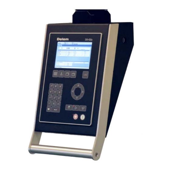
Operation overview and general introduction 1.1. The control unit The control looks as follows: screen function keys arrow keys mode keys numeric keys start/stop The precise outfit of your control may vary. Operation of the control is done with the various keys on the front panel. A description of all keys and their functions is given in the next section. -
Page 6: Operation Modes
1.2. Operation modes The control has the 3 following modes: Manual mode In this mode it is possible to program all parameters of just one bending. This mode is useful for testing and for calibration. Programming In this mode bend programs can be mode programmed and executed. -
Page 7: Programming Modes
1.3. Programming modes The control has the following programming functions: Program In this mode you program the general parameters constants for bend programming. Tools In this mode you program and edit the tools. There are 30 different punches and 30 different dies to program in the program memory. -
Page 8: Other Frontpanel Keys
1.4. Other frontpanel keys The frontpanel consists of the following items: Keyboard: 10 numerical keys (0- 9) incl. alphanumeric input decimal point plus/minus toggle clear key: Clearance of the input data field in the bottom left enter key, to confirm corner on the monitor a programmed value screen... -
Page 9: Software Versions
Return to previous function or abort parameter edit. 1.5. Software versions The version of the software in your control is displayed at the upper side of the menu screen in the programming mode. Example of version number: V 1.2 V stands for version 1 is version number 2 is version level The version number is increased when new features are added to the software, the level... - Page 10 V0812, 1.6...
-
Page 11: Product Programming
Product programming 2.1. Program selection To edit or create a program, proceed as follows: Press this key to activate the automatic mode. Press this key to open the program library. The program library screen appears. Use the arrow keys to move to the desired program in the list. V0812, 2.1... -
Page 12: Program Edit
Use the ‘enter’ key to select the highlighted program. A program can also be selected by entering its number directly. To create a new program: Type a number that does not exist yet. When entered, the control asks whether or not to create a new program. -
Page 13: Parameters Explanation
Use the arrow keys up/down to move the cursor to the desired parameter. Use the arrow keys left/right to browse between the various pages of the bend program. After pressing the enter key the programmed value will be placed at the corresponding parameter. 2.2.2. - Page 14 E-MODULE TENSILE (N/mm²) STRENGTH (N/mm²) 1 = Steel 210.000 2 = Aluminium 70.000 3 = Zinc 94.000 4 = Stainless steel 210.000 5 = Material 5 210.000 6 = Material 6 210.000 Punch ...........UP Number of punch in library.
-
Page 15: Bend Programming
2.3. Bend programming 2.3.1. Introduction The parameters of one bend are divided over 2 screen pages. The bend number, product number and drawing number are displayed in the top row on the screen. Use the key ‘change view’ to switch to another page with bend parameters. - Page 16 Bend methods: air bend The sheet is bent to the programmed angle by bringing the punch to the required depth. The control calculates the required Y-axis position to obtain the programmed angle. bottoming The sheet is bent by squeezing the sheet between the punch and the die.
- Page 17 Auxiliary axis ..........R/Z/Aux. If you have one or more auxiliary axes (for instance a R-axis) the parameters of these axes appear here.
-
Page 18: Bend Parameters - Second Page
2.3.3. Bend parameters - second page This page contains the additional parameters of a bend. Force ...........P The required force during pressing (auto computed). -
Page 19: Bend Parameters - Third Page
Parallelism ..........Y2 Difference of left- and right hand side cylinder (Y1 and Y2). -
Page 20: All Bends View
2.3.5. All bends view When pressing the ‘change view’ button from the general properties page of a bendprogram (Program tab) the list with all bends from the active program is displayed. Within this view all bends can be seen on one page and properties from each bend can be modified. The control can also be started from this view. -
Page 21: Bumping Programming
2.3.6. Bumping programming For big radius bends made with ‘bumping’ it is possible to simple program the required data in a numerical program. First the operator can select the bend method: 0 = Airbend 1 = Bottoming 2 = Bumping When selecting the bend method ‘Bumping’... - Page 22 V0812, 2.12...
-
Page 23: Programming Of Tools
Programming of tools 3.1. Introduction This chapter describes the programming of the tools. Press this key for tool programming. The first time this key is pressed, the screen for punch programming appears. To switch to programming of bottom dies, press this key again. -
Page 24: Programming Of Punches
3.2. Programming of Punches 3.2.1. Punch library The programming of punches is started by pressing the tools key. A maximum of 30 punches can be programmed. Tools that are not programmed show an asterisk (*) beside the tool number. Use the arrow keys left/right to browse to the desired tool in the library. -
Page 25: Punch Parameters
3.2.2. Punch parameters Height ...........H The height of the tool. -
Page 26: Programming Of Bottom Dies
3.3. Programming of bottom dies 3.3.1. Die library The programming of dies is started by pressing the tools key. A maximum of 30 dies can be programmed. Use the arrow keys left/right to browse to the desired tool in the library. V0812, 3.4... -
Page 27: Die Parameters
3.3.2. Die parameters Height ...........H The height of the tool. - Page 28 X-safe ...........SN Calculated safety zone (minimum X-axis value), which will be used in the case an R-axis is mounted.
-
Page 29: Program Constants
Program Constants 4.1. Introduction Press this key to enter the program constants. The program constants are divided across several pages. They are discussed in the following sections. 4.2. General Use the arrow keys left/right to browse through the various pages with parameters. Use the arrow keys up/ down to select individual parameters. - Page 30 Inch/mm-select ......... . .IS 1 = dimensions in inches 0 = dimensions in millimeters Ton/kN select.
-
Page 31: Materials
4.3. Materials In this window, material properties can be programmed. You can edit existing materials, program new materials or delete existing materials. A maximum of 6 materials can be programmed on the control. For each material, three properties are present and can be viewed and edited. Material name. -
Page 32: Program Settings
4.4. Program settings Machine number ......... .MN When there are several bending machines in a factory, it can be useful to give the control on each machine a unique machine number. - Page 33 properties as the active bend. The following properties of a bend are compared: - Material properties - Thickness - Die opening - Die radius - Punch radius - Angle The first five properties of a bend must be exactly the same as the active bend to start a comparison.
-
Page 34: Computation Settings
4.5. Computation settings Data preparation bend allowance ......BA 0 = correction off 1 = correction on With this parameter you can choose whether or not you wish to have programmed values corrected for bend-allowance. -
Page 35: Production Settings
4.6. Production settings Stock count mode .........SC Setting for the stock counter in production mode, to have the stock counter (product counter) count up or down. - Page 36 Intermediate R for X-movement......RS Temporary position for the R-axis, to avoid collision as a result of movement of the X- axis.
-
Page 37: Backgauge Dimensions
4.7. Backgauge dimensions Gauge R offset ..........RO An offset value for the R-axis when the X-axis position is outside the die safety zone. -
Page 38: Maintenance
4.8. Maintenance Hours ........... The number of hours the machine is running. -
Page 39: Data Transfer
4.9. Data transfer From this menu, all program data on the control can be stored on an external USB device or restored from such a device. Backup products Copy all products from the control to the USB disk. Existing products on the USB disk with the same name are replaced. - Page 40 V0812, 4.12...
-
Page 41: Manual Mode
Manual mode 5.1. Introduction Manual mode By pushing this key the CNC is in manual mode. In manual mode you program the parameters for one bending. After pushing the ‘Start’ button all parameters are active and the backgauge will go into position. - Page 42 Material ..........MA Selection of one of the programmed materials, which are used to calculate the bending depths.
- Page 43 Mute ............M Sequence point where the Y-axis is switched from fast closing speed to pressing speed.
-
Page 44: Zoomed Values
Parallelism ..........Y2 Difference of left- and right hand side cylinder (Y1 and Y2). -
Page 45: Manual Operation Of The Axes
5.4. Manual operation of the axes 5.4.1. General Press this key to activate the manual movement mode. It is possible to move an axis by pressing the arrow keys on the front panel of the control. After pressing the key ‘manual pos’, the following screen appears: Put the cursor bar on the axis you wish to move with the arrow keys. -
Page 46: To Teach
First you select the respective backgauge axis with help of the "Manual positioning"-key, so that you will see the cursor bar at the required axis. Then you can move the axis with help of the keys. - Y-axis: With the keys the punch can be positioned manually in the same way as for the auxiliary axes. This operation is only possible in "Start"... -
Page 47: Automatic Mode
Automatic mode 6.1. Introduction In the automatic mode a bend program can be executed automatically bend by bend after pushing the ‘start’-key. When a new bending program is selected you must check your tools and tool positions in your machine. In the header information is displayed on the number of bends, the repetition of a bend, the product number and the drawing number. -
Page 48: Parameters
6.2. Parameters Select repeat ..........CY Selection of one of the repeated steps of one bend. - Page 49 6.3. Zoomed values When the function key ‘zoomed values’ has been pressed, the control switches to a new view with only axes values on the screen. V0711, 6.3...
- Page 50 6.4. Manual operation of the axes Press this key to activate the manual movement mode. It is possible to move an axis by pressing the arrow keys on the front panel of the control. After pressing the key ‘manual pos’, the following screen appears: The procedure for manual movement is described in section 5.2.
- Page 51 Parameter index Method ......5.2 Mute ......3.5 Mute .
- Page 52 V0812, A.2...
Need help?
Do you have a question about the DA-52s and is the answer not in the manual?
Questions and answers