Table of Contents
Advertisement
Quick Links
Advertisement
Table of Contents

Related Manuals for Delem DAC-310


Summary of Contents for Delem DAC-310
- Page 1 Delem DAC-310 Installation manual V1204, 1.1...
-
Page 2: Table Of Contents
Delem Table of contents PART I - HARDWARE DESCRIPTION ................3 INTRODUCTION ......................4 SPECIFICATIONS ......................5 2.1. Physical dimensions ....................5 2.2. Environmental conditions................... 5 2.3. Technical specifications ..................... 6 SCHEMATICS ......................... 7 3.1. Connection diagrams....................7 3.2. Physical dimensions ....................10 3.3. -
Page 3: Part I - Hardware Description
Delem Part I - Hardware description This section contains the hardware specifications of a Delem DAC-310 control. V1204, 1.3... -
Page 4: Introduction
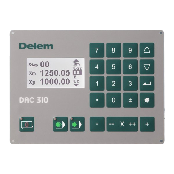
The DAC-310 is a universal programmable controller, designed to control positioning of machine parts such as the backgauge control of an industrial shear. The DAC-310 is capable of controlling servo-loop systems, a one- or two-speed AC or DC drive system. -
Page 5: Specifications
Delem 2. Specifications 2.1. Physical dimensions For the dimensions of the DAC-310 control, see the included drawings at the end of this section. 2.2. Environmental conditions The following environment specification values are valid for a DAC-310 control: Ambient temperature 0 - 50°C Storage temperature min. -
Page 6: Technical Specifications
Delem 2.3. Technical specifications Power supply 18 - 28 VDC Display LCD/STN 128 x 64 black/white Interfaces 1 x Encoder 1 x RS-232 (service only) 4 x Digital input, 24V 8 x Digital output, 24V 1 x analog output 0 ± 10V 1 x analog input 0 - 10V V1204, 1.6... -
Page 7: Schematics
Delem 3. Schematics 3.1. Connection diagrams V1204, 1.7... - Page 8 Delem V1204, 1.8...
- Page 9 Delem V1204, 1.9...
-
Page 10: Physical Dimensions
Delem 3.2. Physical dimensions V1204, 1.10... -
Page 11: Time Cycle
Delem 3.3. Time cycle V1204, 1.11... -
Page 12: Part Ii - Machine Parameters
Delem Part II - Machine parameters This section will describe the necessary settings of a DAC-310 control regarding machine settings. V1204, 2.1... -
Page 13: I/O Assignments
Delem 1. I/O assignments The DAC-310 has several programmable features. These features can be enabled or disabled in software. Depending on these featues, a number of logical signals can be mapped to the I/O pins of the DAC. This means the system programmer can enable the necessary signals and assign them to output pins. - Page 14 Delem Each choice opens a sub-menu with an array of the logical signals and available connector pins. The screen for digital inputs looks as follows: In the top row, the available connector pins (D1 - D4) are shown. In the left column, the logical signals are listed.
- Page 15 Delem Machine Ready Signal that indicates the machine is ready. When it is low, the control cannot be started. When it is high, the control can be started and the Hours counter (parameter 91) keeps track of the time. Digital output signals...
- Page 16 Delem Analogue output signals Code Name Description Speed Speed output. SPD > 0: positive direction, encoder upcounting SPD < 0: negative direction, encoder downcounting V1204, 2.5...
-
Page 17: The Machine Parameters
Delem 2. The machine parameters 2.1. The menu The machine parameters are only accessible with a special entry code. Machine parameters should be adjusted by authorized personnel only. To enter the machine parameters menu: • scroll to the M field •... - Page 18 Delem 30 Stop time T 31 Overrun 32 Overrun wait time 33 DC slow speed 34 DC fast speed 35 Unipolar output 40 Servo gain 41 Servo switch 42 Servo ramp 43 Servo acceleration 44 Manual movement slow speed 45 Manual movement fast speed...
-
Page 19: Drive Types
Delem 2.3. Drive types The DAC control can be programmed to drive different axis types: • 1-speed AC or DC drive • 2-speed AC or DC drive • Servo motor drive The required system can be programmed with the parameter ‘Drive type’. -
Page 20: Ac Drive
Delem 2.3.2. AC drive In this paragraph, the parameters for axes with AC drives are discussed. When using AC drives, it is possible to program 1-side positioning or 2-side positioning. Beside this, it must be indicated whether a one-speed or 2-speed motor drive is used. - Page 21 Delem For this axis, the parameter ‘Breakpoint slow speed’ (BSS) must be programmed. This parameter defines the switch-off points for the axis movement. The value depends on the known deceleration rate of the axis equipment. If the BSS is not accurate enough to reach the programmed position, the parameter ‘Stop time’...
-
Page 22: Unipolar System
Delem speed programmed position BSS > BFS > position One side positioning is useful to overcome mechanical inaccuracies in the spindle. Final positioning of the axis is always done from a higher to a lower position. So when the axis moves from a high to a low position, positioning is done immediatly. - Page 23 Delem Bipolair: Unipolair: DAC-310 DAC-310 0 +/- 10V 0 - 10V + - In case of a 2-speed unipolar system, you should consider your I/O configuration with care. The illustration above is an example of a 2-speed unipolar implementation. The outputs 1 and 2 of the DAC are used for indication of positive and negative movement.
-
Page 24: Parameter Explanation
Delem 2.4. Parameter explanation Parameter 00: Software version Range : - Unit Default : - Function Version number of the current software. Parameter 01: Drive type Range : 1 - 3 Unit Default : 3 Function The type of motor system that is to be controlled. - Page 25 Delem Parameter 03: Scale factor Range : 0.001 - 999.999 Unit : pulse/mm Default : 100.000 Function Sets the scaling between encoder pulses and millimeters. The encoder gives an exact number of pulses over a mm displacement. This value must be programmed here.
- Page 26 Delem Parameter 06: Minimum backgauge position Range : 0 - 9999 Unit : mm Default : 0 Function Minimum backgauge position. The axis will never be controlled to a lower position than programmed here. Parameter 07: Spindle allowance Range : 0 - 1...
- Page 27 Delem Parameter 13: Indexing Range : 0 - 1 Unit Default : 1 Function Each time the supply voltage is switched on, the reference position must be passed. This can be done in two ways: 0 = no reference encoder used, the actual backgauge position will be memorized after power down.
- Page 28 Delem System 1 is the standard reference search system. For this system the motor drive must be equipped with a direction sensitive enable/disable input. System 2 Now the motordrive does not need any direction sensitive enable/disable input anymore. Also you are free where you place the reference search direction switch (RSD). It may be the same switch;...
- Page 29 Delem Parameter 21: Auto retract Range : 0 - 1 Unit Default : 0 Function When set to 1, retract is automatically started when ST goes low (start cutting). Parameter 22: Minimum retract Range : 0.0 – 9999.9 Unit : mm Default : 0.0...
- Page 30 Delem Parameter 27: Brake delay Range : 0.0 - 0.99 Unit : seconds Default : 0.00 Function Delay time before AC brake is activated. Parameter 28: Breakpoint Fast Speed BFS Range : 0.0 - 9999.9 Unit : mm Default : 10.0 Function Switch point from high speed to slow speed.
- Page 31 Delem Parameter 31: Overrun Range : 0.0 - 9999.9 Unit : mm Default : 1.0 Function Overrun distance in case of one side positioning. One-side positioning is chosen with parameter 11, ‘spindle allowance’. An overrun is also done when an AC-drive must change position over a small distance, smaller than BSS.
- Page 32 Delem Parameter 35: Unipolar output Range : 0 - 1 Unit Default : 0 Function Function to switch unipolar AC control on/off. When set to 1, the analog speed output will only output a positive signal, no matter which direction the axis is moving. This can be used to connect a frequency regulator for 1 or 2-speed AC control.
- Page 33 Delem Parameter 43: Servo acceleration Range : 5 - 1275 Unit : msec Default : 100 Function This parameter defines the time needed to reach the full speed output. servo acceleration speed Parameter 44: Manual movement low speed Range : 1 - 99.9...
- Page 34 Delem Parameter 46: Reference search speed Range : 1 - 100 Unit Default : 50 Function Axis speed during reference searching. Parameter 50: Stroke mode Range : 0 - 2 Unit Default : 0 Function When the stroke option is enabled, the user can program the desired stroke length as a percentage (0-100%) of the maximum stroke length.
- Page 35 When the percentage value is programmed zero then the stroke limitation is not active in that step. In this case the EOS output will not be activated. Note: When the DAC-310 is stopped, the EOS output will be off. Parameter 52: Stroke AD min Range : 0 - 255...
- Page 36 Delem Parameter 55: Angle control Range : 0 - 1 Unit Default : 0 Function Switch Angle control ON or OFF. 0 = No angle control 1 = Angle control In case of angle control, the following I/O is used: •...
- Page 37 Delem Parameter 59: Angle AD max Range : 0 - 255 Unit : AD value Default : 255 Function The AD value corresponding with the maximum angle. Only valid when angle option enabled. Parameter 60: Angle prestop positive Range : 0 - 99...
- Page 38 Delem Parameter 61: Angle prestop negative Range : 0 - 99 Unit : AD value Default : 0 Function This parameter has the same definition as parameter "Angle Prestop Positive" but only in the negative direction of the angle adjustment (smaller angle).
- Page 39 Delem Parameter 68: Maximum Gap Range : 0.00 - 9.99 Unit : mm Default : 2.5 Function The maximum possible gap. Only valid when gap control is enabled. Parameter 69: Gap AD min Range : 0 - 255 Unit : AD value...
- Page 40 Delem Parameter 71: Gap prestop positive Range : 0 - 99 Unit : AD value Default : 0 Function Due to the inertia of the Gap system there can be some overshoot after the control output has been switched off. To prevent such overshoot, the 'Gap prestop' can be programmed.
- Page 41 Delem Parameter 75: Enable Func Range : 0 - 1 Unit Default : 0 Function Enables F (function) parameter in the user interface. Parameter 76: Enable Cor Range : 0 - 1 Unit Default : 0 Function Enables Cor (correction) parameter in the user interface.
- Page 42 Delem Parameter 90: Serial number Range : - Unit Default : - Function Displays the serial number of the controller. This value cannot be changed. Parameter 91: Hours Range : - Unit : hours Default : 0 Function Displays the total number of hours the machine has been running. The value of this parameter is the total time the MR input has been high.
-
Page 43: Software Settings
• Delem back-up software for transmission of machine settings. The Delem back-up software must be installed on the PC. All actions, storage and restoration of settings, are done with this program. Just make sure the necessary cables are connected and the DAC control is switched on. - Page 44 Delem To start the back-up tool, simply double-click its icon. A window appears: After start-up, the two large buttons for back-up and restore cannot be selected yet. First, click on the button ‘Connect...’ to establish a connection between the software and the DAC control.
-
Page 45: Upgrade Control
PC (COM1). You also need a program that will load the new software into the control. This program can be requested from Delem. Note : before starting an upgrade, first perform a back-up of your control settings. See the previous section for more information about back-up and restore. -
Page 46: Part Iii - The Diagnostic Program
Delem Part III - The diagnostic program To be able to test a DAC-310 control, it has been equipped with a diagnostic program. With the test functions of the diagnostic program the service engineer can test the control itself and the communications to externally connected system components. -
Page 47: General Remarks
In the description of the tests it is indicated which component(s) is(are) responsible for correct functioning of that particular part. See for exploded view drawing with all internal cables and cards of the DAC-310 control the included diagrams at the end of part I. -
Page 48: Test-Menu
Delem 2. Test-menu 2.1. Start To select the diagnostic program the following steps have to be performed: move the cursor to the M field enter the access code 741. The diagnostic screen of the control looks as follows: To end the diagnostic program the power supply to the control can be switched off and then on again to enter the normal operation menu. -
Page 49: Test Functions
Delem 2.2. Test functions In 1 - 4 These digits refer to the digital inputs of the control. To test the digital inputs, apply 24V to the inputs and check if they change to ‘1’. Out 1-8 These digits refer to the digital outputs of the control. To change an output, move the cursor to the required output number and press ENTER. -
Page 50: Appendix A - Reference List
Delem Appendix A - Reference list DAC-310 Operation manual...
Need help?
Do you have a question about the DAC-310 and is the answer not in the manual?
Questions and answers