Table of Contents
Advertisement
Quick Links
Advertisement
Table of Contents

Related Manuals for Delem DA-52s


Summary of Contents for Delem DA-52s
- Page 1 Delem DA-52s Installation Manual V0614, 1.1...
- Page 2 The General Terms and Conditions of Delivery of Delem shall apply to this product. These conditions are available from Delem on request. • This manual does not entitle you to any rights. Delem reserves the right to change this manual without prior warning. •...
-
Page 3: Table Of Contents
Modify the update .................... 8 1.3. Option installation ....................10 1.3.1. Request option on the control ................ 10 1.3.2. Request option code at Delem ..............13 WINDOWS TASKS ...................... 16 2.1. Windows introduction .................... 16 2.2. Directory structure ....................18 2.3. - Page 4 Delem TEST-MENU ........................3 2.1. Start diagnostic mode ..................... 3 2.2. The menu ........................ 3 KEY TEST ........................4 SCREEN TEST....................... 5 I/O TEST......................... 7 5.1. Test screen ......................7 5.2. Testing the valve deflection ..................9 APPENDIX A - REFERENCE LIST ..................1...
-
Page 5: Part I - Hardware Description
Delem Part I - Hardware description This section contains the hardware specifications of a Delem control DA-52s. V0614, 1.5... -
Page 6: Introduction
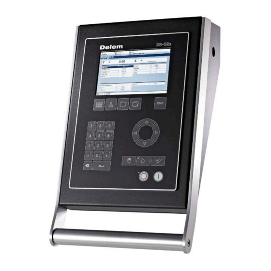
Delem 1. Introduction This manual contains information necessary for installation of a DA-52s control. Such a control is the heart of a pressbrake control system with which a pressbrake machine is controlled. Figure 1.a A DA-52s control combines different tasks in one unit: - programming products and tools;... -
Page 7: Specifications
Delem 2. Specifications 2.1. Physical dimensions For the dimensions of the DA-52s control, see the included drawings at the end of this section. The following environment specification values are valid for a DA-52s control: Ambient temperature 5 - 45°C Warning: Avoid long-term exposure of the control to direct sunlight. -
Page 8: Technical Specifications
Delem 2.2. Technical specifications Power supply 18 - 28 VDC 80 W Display LCD/TFT colour 7” Widescreen 800 x 480 Interfaces Valve connector (see chapter 3) Analog A/B 4 x Encoder 1 x RS-232 1 x USB digital I/O Memory Flash memory, 64 MB embedded V0614, 1.8... -
Page 9: System I/O
Delem 3. System I/O 3.1. Introduction Figure 3.a The DA-52s control is equipped with a large set of connectors for various functions: - valve control - system I/O - encoder feedback - communication - USB The various connectors are discussed in the following sections. -
Page 10: Power Supply
Delem 3.2. Power supply 7-pole male binder connector 3.3. USB connector The control has been equipped with one standard USB connector, according to the USB 1.1 specification. V0614, 1.10... -
Page 11: Valve Connector
Delem 3.4. Valve connector 16-pin connector for valve control. Standard: P-VA The connector is used for pressure valve control. The control signals for the valve amplifiers run through connector Analog B. An example of the required wiring is given in diagram 8061- 102. -
Page 12: Analog A
Delem 3.5. Analog A Connector Analog A provides several analog signals, two analog outputs and four analog inputs. See schematic 8061-101 for connection details. Specifications for Analog I/O Analogue inputs (4x) 0-10V, input impedance 44 kΩ Reference voltage (2x) 10V + 2%... -
Page 13: Analog B
Delem 3.6. Analog B Connector Analog B provides several analog signals, two analog outputs and two analog inputs. It also includes power supply for possible valve position transducers (LVDT). See schematic 8061-101 for connection details. Specifications for Analog I/O Analogue inputs (2x) 0-12V / -10V ... - Page 14 See schematic 8061-101 for connection details. The use of I/O pins depends on the application and machine settings. For the purpose of all assigned I/O signals we refer to the Delem machine parameter manual. I/O power supply: 24 V DC + 20% 10A max.
- Page 15 Delem CN6: Pins 25 - 32 Digital Outputs (4x) Voltage Current ON state 20-28 V DC 0.5 A max. OFF state 0.1 mA max. (leakage current) Digital Inputs (4x) Voltage Current ON state 9-28 V DC 20mA max. OFF state 0 - 4 V DC 1 mA max.
-
Page 16: Encoders
Delem 3.8. Encoders 9-pole SUBD female encoder interface 5V DC/250 mA or 12V DC/200 mA 12 V or 5 V single ended or 5 V differential Max. count frequency 1 MHz See schematic 8061-101 for connection details. Notes: • In case of 12VSE encoder, connect pins 6, 7, 8 and 9 with each other. -
Page 17: Spare Parts
4. Spare parts 4.1. Introduction The following table gives an overview of the available spare parts for the DA-52s controls. The next chapter contains an exploded view of a DA-52s control, in which the same spare part numbers are used. Number... -
Page 18: Schematics
Delem 5. Schematics The following pages show several schematics about the DA-52s control. V0614, 1.18... - Page 20 1 2 3 4 5 6 7 8 9 1 2 3 4 5 6 7 8 9 10 11 12 13 14 15...
- Page 22 1 2 3 4 5 6 7 8 9 1 2 3 4 5 6 7 8 9 10 11 12 13 14 15...
- Page 23 6 7 8 9 1 2 3 4 5 6 7 8 9 10 11 12 13 14 15...
- Page 24 6 7 8 9 1 2 3 4 5 6 7 8 9 10 11 12 13 14 15...
- Page 25 6 7 8 9 1 2 3 4 5 6 7 8 9 10 11 12 13 14 15...
- Page 26 6 7 8 9 1 2 3 4 5 6 7 8 9 10 11 12 13 14 15...
- Page 27 6 7 8 9 1 2 3 4 5 6 7 8 9 10 11 12 13 14 15...
-
Page 28: Part Ii - Machine Settings
Delem Part II - Machine settings This section will describe the necessary settings of a DA-52s control regarding machine settings. V0614, 2.1... -
Page 29: The Machine Parameters
14753 The main menu of the machine parameters appears. For a description of menu 1 to 4 we refer to the Delem machine parameter manual [1]. In this chapter, the installation of new software and options is explained. -
Page 30: Update Control
New software can be loaded from a portable USB drive. A CD-ROM with the latest control software can be requested at Delem. It contains all software necessary to perform an update. To prepare for an update, copy the contents to the USB disk. - Page 31 • etc... A set called ‘DA-52s Application’ is used to upgrade the control Operating system and the DA application, without affecting the existing user data (products, tools, materials) on the control. A set called ‘DA-52s Factory Default’ is typically used for first time installation of all software on a DA-52s control, including example products, tools and materials.
- Page 32 Delem Figure 1.c This third window shows the final information about the software update and a warning not to interrupt the update process. On the bottom, two parameters are available to modify the update behaviour: Show notifications Determine when messages must be displayed during the update.
- Page 33 'Automatic reboot') show a message the control should be restarted. Figure 1.e In case the update stops when finished, press the END key to start the control. After this reboot, the control will start as usual with the Delem DA application. V0614, 2.6...
-
Page 34: Backup/Restore The Application
Delem 1.2.2. Backup/restore the application Backup The update program offers the possibility to make a backup of the current software set that is installed on the control. This way, the current application is saved with its existing settings before the software is updated. With this procedure all data is stored: •... -
Page 35: Modify The Update
The names you see in the list are retrieved from each available configuration file. You can change the content to add items to the standard Delem update set or create a small set which can be run separately, after the Delem update. A .cfg file contains six sections: 1. - Page 36 Delem updater. The lines following after that give additional information which is displayed in the updater window. The update program is delivered with a text file, called ‘UpdaterReadme.txt’. Also, the standard configuration file ‘Application.cfg’ contains a lot of comment which describes the possibilities of the update set.
-
Page 37: Option Installation
It is possible to install software options on the control. Options can be requested at Delem. Options for a DA-52s control can be purchased at any moment. It is done by buying an ‘Option Voucher’ for a specific function (e.g. 2nd servo axis). A new option voucher is valid for any DA-52s control. - Page 38 Delem Figure 1.i This window shows which options are available. To activate an option, press the key (Request options) to start option installation. When pressed, the screen looks as follows: Figure 1.j At the top of the screen, the serial number of the control is displayed.
- Page 39 (certificates.delem.com); this is explained in detail in the next paragraph; • obtain a certificate file from Delem and put it on a USB disk or on the control disk; • in the option program, select the requested option and press the button ‘import certificate’.
-
Page 40: Request Option Code At Delem
There are different ways to send the UIR file to Delem. The simplest (and slowest) way is put the file on a portable disk and send this to Delem. After a certain period, you will receive a disk with the license file. - Page 41 Delem Figure 1.l • press the button ‘submit’ below the field; Figure 1.m V0614, 2.14...
- Page 42 When a license has been registered, the file with the registration code is stored on the control disk, in the directory \Hard Disk\Delem\Licenses. The file has the extension ‘.lic’. It is possible to copy these files to a USB disk. When the control has been re-installed or rescued, the license files can be copied back into the ‘Licenses’...
-
Page 43: Windows Tasks
Figure 2.a To switch to Windows without opening any application, click on the pencil symbol in the lower right corner of the screen. The Delem control application is switched to the background, but remains active. To activate a certain application, click on the Start button in the lower left corner of the screen. - Page 44 Delem The Delem control application can be switched off. The application is switched off as follows: • move the mouse to the lower edge of the screen: the Windows taskbar appears; • move the pointer to the expression ‘Delem controller’;...
-
Page 45: Directory Structure
Some important directories: \Hard Disk\Delem\Bin This directory contains the Delem control application files. The control application ‘Delem.exe’ is automatically started when the control is activated. Furthermore the Delem sequencer file and the KO-Table are located here. \Hard Disk\Delem\Data Directory with the ‘products’ and ‘tools’ subdirectories, which contain all products and tools for this control. -
Page 46: Important Files
A lot of control settings are stored in files, which are located on the hard disk of the control. This is the case for the Delem application as well as for the Windows platform. Whenever the control is (re)started, the software will search for these files and retrieve the last saved settings. - Page 47 Explorer and as such it is protected against unauthorised user actions. A hidden file can also not be opened from within Windows applications, such as Wordpad. The Delem application can still open a necessary settings file, even though it is hidden.
- Page 48 This file contains the material properties of the Delem control application. Since this file is a plain text file, it is possible to program materials for the Delem application by editing this file directly. Normally, materials are programmed in the menu ‘program constants’.
- Page 49 Delem Files with Windows settings: AUTOEXEC.BAT Location: \Hard Disk File with commands, which are executed at start-up of the control. This file can be edited through the utility ‘Autoexec.exe’. See section 2.7 for more information. NK.BIN Location: \Hard Disk Windows archive. Do nothing with this file! If this file gets deleted or lost, the control will not...
-
Page 50: Editing The Autoexec.bat
Common tasks for such a file can be to copy files to or from the flash memory. In the standard file, one task is implemented: activate the Delem application. Other tasks can be added if required. - Page 51 Lines in the file that start with ‘REM’ are considered as comment. In the beginning of the file, the ‘if’ instruction checks if the Delem application has a KO-table to work with. If such a KO-table is present, the subsequent instruction is skipped.
-
Page 52: Control Rescue Procedure
Delem 2.5. Control Rescue procedure The Rescue procedure for the Delem control is meant to re-install all original software on the control. It is meant as a last resort, when other attempts to ‘cure’ the control have failed and/or the control does no longer boot from the internal flash memory). - Page 53 8. Follow the update procedure as described in paragraph 1.2.1, Update procedure. What to do when the Control does not boot? (The display shows a black screen with a Delem logo) Preparation To perform the procedure on the control the following is necessary:...
- Page 54 Delem 5. Select option: 2 6. Recover files from the control. One of following screens will show: Follow the instruction on the screen (for backup use the empty USB-stick). Follow instruction on the screen. 7. After the backup the kernel will be installed, follow the instructions on the screen.
- Page 55 11. Plug in the USB-stick with a backup- or the stick with the recovered-data) Select "Import Certificate" and find the license files on the USB-stick. Find it in: \\Delem\Licences\ 13. Optionally follow the same procedure for the X2 option. 14. Via Machine Parameters you can now choose to update the control with the rescue stick.
-
Page 56: Sequencer Adjustment
Delem 2.6. Sequencer adjustment The sequencer is the built-in PLC function of the Delem system. The text file with sequencer code is stored on the hard disk of the control, in the file seq_inp.txt. This file can be edited with the application Notepad that is built-in on the control. An alternative could be to copy the file to a USB disk and edit the file from a PC. - Page 57 *.DEF to the sequencer directory in the control. After installing the new sequencer the parameter ‘Sequencer from USB memory’ can be switched off again. For a description of sequencer programming we refer to the Delem sequencer programming language manual [2]. V0614, 2.30...
-
Page 58: Analysis Program
Upon start-up, the program will first prompt for an access code: Figure 2.m Here you must enter a ‘level 2’ code, which is also used to modify all Delem machine parameters in the DA application. The default access code here is 32157. - Page 59 Delem To record a bend cycle, use the ‘start measure’ command. The program will show the following dialog: Figure 2.n This means the analysis tool is now waiting for a bend cycle to be executed. Now switch to the DA application and execute a bend cycle in the normal way. The analysis program actually starts recording when a fast closing or a pressing command is activated.
- Page 60 Delem A typical analysis screen of one cycle could look as follows: Figure 2.p The toolbar at the top of the screen has the following commands: create a new file for recording of cycles open open an existing analysis file...
- Page 61 • digital output signals • digital input signals For the meaning of all signals we refer to the Delem machine parameter manual, where all signals are described in detail. Remarks: • If cycle files must be kept for further analysis, it is recommended to store them in non- volatile memory.
-
Page 62: Part Iii - The Diagnostic Program
Delem Part III - The diagnostic program To be able to test a DA-52s control, it has been equipped with a diagnostic program. With the test functions of the diagnostic program the service engineer can test the control itself and the communications to externally connected system components. -
Page 63: General Remarks
In the description of the tests it is indicated which component(s) is(are) responsible for correct functioning of that particular part. See for exploded view drawing with all internal cables and cards of the DA-52s controls the included diagrams at the end of part I. -
Page 64: Test-Menu
To end the diagnostic program the power supply to the control can be switched off and then on again to enter the normal operation menu. It is also possible to leave the diagnostic program with the ‘END’-key. The Delem application will restart. -
Page 65: Key Test
Delem 3. Key test Function This test is meant to check the functioning of all the frontpanel keys. Description First you see a matrix with all keys, like in figure 3.a. Figure 3.a • Each time you press a key on the front, the corresponding position on the screen will give a unique indication. -
Page 66: Screen Test
Delem 4. Screen test Function The screen of the control can be tested with 2 different test programs, to be selected with the front panel keys. Figure 4.a colortest Check the display of colours on the screen. V0614, 3.5... - Page 67 Delem Colortest To get a good idea about the colour setting and correct functioning of the colour screen you will see a number of vertical bars. It is important that the 3 main colours are available (red, green and blue).
-
Page 68: I/O Test
Delem 5. I/O test 5.1. Test screen Description In this screen the system I/O of the control can be tested and monitored. Analog and digital outputs can be set high and low with keys on the front panel. The read-out of analog inputs and the encoders is continuously. When a reference pulse of the linear scales is received in the electronics, the corresponding measured value will shortly be highlighted in inverse colour. - Page 69 The value on the screen is the read-out of the voltage in DA-points which is offered to the analogue input. By varying the voltage the read-out should vary likewise. Failure External electronics, DA-52s or the wiring (including connectors). V0614, 3.8...
-
Page 70: Testing The Valve Deflection
The test procedure for valve deflection depends on the type of valves that is installed. On the following two pages two different procedures are described. The first procedure is for Hoerbiger valves, which are connected directly to the DA-52s. The second procedure must be followed when external valve amplifiers are used to control the valves. - Page 71 DA-points (0 DA = 0 mA). The current can be measured with an ammeter in series with the pressure valve. Note The maximum allowed DA-points per installed current type of the pressure valve. Failure External electronics, wiring, valves or DA-52s. Press the END-key to finish this test. V0614, 3.10...
- Page 72 4. Repeat these steps for the other valve. 5. Further fine-tuning can be done through the calibration procedure as described in the Delem machine parameter manual at parameter 15, ‘Calibrate valves’. That procedure is designed especially for external valve amplifiers.
-
Page 73: Appendix A - Reference List
Delem Appendix A - Reference list Delem machine parameters Delem Sequencer Programming Language Reference manual for operation of DA-52s V0614, A.1...
Need help?
Do you have a question about the DA-52s and is the answer not in the manual?
Questions and answers