
Related Manuals for Delem DA-58T


Summary of Contents for Delem DA-58T
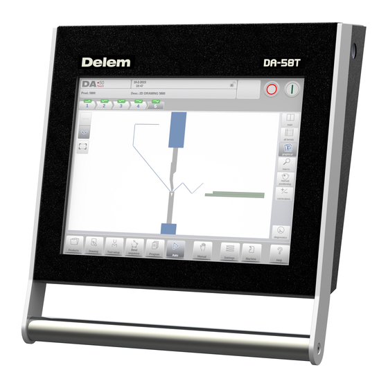
- Page 1 DA-58T Reference Manual Operation of Version 1.1 English 8086-913B Manual version V0215...
- Page 2 Preface This manual describes the operation of the Delem control type DA-58T and is meant for oper- ators who are instructed for operation of the total machine. Delem Limited warranty • This manual does not entitle you to any rights. Delem reserves the right to change this manual without prior warning.
-
Page 3: Table Of Contents
Table of contents 1. Operation overview and general introduction ....1.1 1.1. The control unit ........... . 1.1 1.2. - Page 4 4.2. Standard procedure ..........4.1 4.3.
- Page 5 8.6. Diagnostics ............8.14 8.6.1.
- Page 6 V0215, 4...
-
Page 7: Operation Overview And General Introduction
Operation overview and general introduction 1.1. The control unit The control looks as follows: The precise outfit of your control may vary. Operation of the control is mainly done over the touchscreen. A description of the functions and available touch controls is given in the next sections of this manual, aside of the description of the specific functions. -
Page 8: Front Control Elements
1.2. Front control elements The Start and Stop button, integrated in the touch screen user interface: Stop button + Start button V0215, 1.2... -
Page 9: Usb Connectors
1.3. USB connectors At the right side of the control a USB port is available for connection of external devices, such as a memory stick or an external keyboard or mouse. V0215, 1.3... -
Page 10: Operation And Programming Modes
1.4. Operation and programming modes The DA-Touch control's main screen looks as follows: Depending on the navigation button which is active, the screen will differ. The above main screen will appear having the Products function active. Just by tapping the various modes, the specific mode will be selected. The structure of the main screen is as follows: Title panel In the top the title panel is always shown. - Page 11 Information panel In the information panel all functions and visualisation related to the selected modus are displayed and can be found. Command panel The command panel is part of the Information panel and is the location where the controls related to the Information panel can be found. Navigation panel The Navigation panel is the area where all the major modes can be found.
- Page 12 Explanation of the main modes / navigation buttons To make a new program and select a program out of the product library. To draw/create a new product or edit an existing product (graphically). To setup the machine and modify existing tool setups. To compute and modify the bend sequence.
-
Page 13: Getting Started
1.5. Getting started 1.5.1. Introduction In order to obtain a bend program for a product, the control offers the possibility to create a product drawing and calculate a valid bend sequence for the product. With this information, a product program is generated. This is done with the following steps: Go to the Products mode in the navigation panel and start a new product by tap- ping New Product. -
Page 14: Determine Bend Sequence
angles can be optimized by the Value setting method. Just tap 2 times on the value of the line length or angle to change and the keyboard will pop-up. The value can be entered in 2 ways of confirmation: • Enter function •... -
Page 15: Numerical Program
More information about this can be found in chapters 4 and 5. Bending sequence computation • Automatic computation for minimum production time • Interactive bend sequence determination • Manual bend sequence determination • Collision visualization of product with tools and machine •... -
Page 16: Back-Up Data, External Storage
Both product and tool files can be stored externally. Depending on the configuration, these files can be stored on a network or on a USB stick. This facilitates a back-up of important data and the possibility to exchange files between Delem controls. More information about this can be found in chapter 9. -
Page 17: Programming Aids
1.6. Programming aids 1.6.1. Help text This control is equipped with an on-line Help function. When the Help-button in the navigation panel is pressed context sensitive help will be provided. To activate a help window for a parameter tap the Help button in the navigation panel. A pop-up window appears with information on the active parameter. -
Page 18: Listbox Functionality
1.6.2. Listbox functionality Several parameters on the control have a limited number of possible values. When selecting such a parameter, by tapping the parameter line on the screen, the list of options will open up near the position where you tapped the line, and the desired value can be selected. To undo the selection and the opened listbox, tapping outside the box will make it close without changing the selected parameter. -
Page 19: Navigation
1.6.4. Navigation Within some modes, the program screens are divided into tabs. The tabs can easily be selected by just tapping them. When a tab is not completely visible or not visible at all, just by dragging the tab row horizontally, the desired tab can be "pulled" in sight and be selected. -
Page 20: Typing Alphanumeric Characters Vs. Special Characters
1.6.6. Typing alphanumeric characters vs. special characters Both alphanumeric characters and special characters can be used throughout the control. A full on-screen alphanumerical keyboard will pop up when required. When editing a field which is pure numeric, the alphanumeric characters will be "greyed-out" and only the numerical keypad can be used. -
Page 21: Network
1.6.7. Network The CNC control optionally can be equipped with a network interface. The network function offers the operators the possibility to import product files directly from the network directories or to export the finished product files to the required network directory. Chapter 9 about backup/restore in Settings mode contains more information about networking possibilities. -
Page 22: Keylock Function
1.6.8. Keylock function To prevent for changes to products or programs, the keylock function offers the possibility to lock the control. There are two levels of locking the control. Program Lock and Machine Lock. • In Program Lock, only a product can be selected and executed in Automatic mode. •... - Page 23 Codes can be changed upon desire. The procedure to manages codes can be found in the Installation manual. V0215, 1.17...
-
Page 24: Manual Positioning
1.6.9. Manual positioning On the manual positioning page in Manual mode and Automatic mode a slider at the bottom of the screen can be used to position the axis. The distance moved with the slider determines the speed of the axis. When the slider is released, the axis stops. The buttons at each end of the slider can be used to fine-tune the axis position. -
Page 25: Software Versions
1.6.10. Software versions The version of the software in your control is displayed at the System Information tab in the Machine menu. Example of version number: V 1.2.3 V stands for version V 1.x.x is the major version number V x.2.x is the minor version number V x.x.3 is the update version number The major version number is increased when new major features are added to the software. - Page 26 V0215, 1.20...
-
Page 27: Products, The Product Library
Products, the product library 2.1. Introduction In the Products mode existing, previously produced, products can be selected to start production or for modification in order to make a similar product. To start making a new product or program New Product or New Program can be used from this mode. 2.1.1. -
Page 28: Product Selection
the product has a CNC program, there is no drawing the product consists of a 2D drawing, there is no CNC program the product has a 2D drawing and a CNC program If a product program is already active its ID is shown in the top of the screen. A program can be loaded by tapping the product ID or any other part of the product's line. -
Page 29: New Product, Starting A New Graphical Product
2.1.3. New Product, starting a new graphical product To start a new graphical product tap New Product. After New Product is chosen, the programming of a new product starts with its general details like Product ID, Thickness and Material. V0215, 2.3... -
Page 30: New Program, Starting A Numerical Program
2.1.4. New Program, starting a numerical program To start a new numerical program tap New Program. After New Program is chosen, the programming starts with its general details like e.g. Product ID, Thickness and Material. The shown general tab is next to the successive tabs which are ready for programming the first bend. -
Page 31: Edit, Copying And Deleting A Product Or Program
2.1.5. Edit, Copying and Deleting a product or program To delete a product in the Products mode select a product by tapping it. It will be selected. After that tap Edit and use Delete. To finally delete it confirm the question. To delete all products and programs at ones, tap Delete All. -
Page 32: Product Lock/Unlock
2.1.6. Product Lock/Unlock The product Lock/Unlock function provides a simple method to prevent accidental changes to finished programs or products. In this way products which have been tuned and found to be good cannot be changed unless the product is unlocked. When tapping on Edit the Lock Product / Unlock Product feature can be switched for each product or program. -
Page 33: Filter Function
2.1.7. Filter function To make finding products easier the filter function enables live searches through-out the Products mode. When tapping Filter, the filter screen will show. By typing the desired filter string, optionally devided by spaces, the live search will start. Optionally a different view can be selected. -
Page 34: Change Directory
Tap Make Subdir and enter the new name. Subdirectories are called subdirectories because these directories reside under the local directory 'DELEM\PRODUCTS'. The name of the subdirectory cannot be changed. In this menu it is not possible to copy products from one subdirectory to another subdirectory;... -
Page 35: Network Product Selection (Only Available When Network Option Has Been Installed)
2.1.9. Network product selection (only available when Network option has been installed) When a networkdirectory has been mounted in the control this mounted directory can be found under Network. Network is available next to the Product directory when using change directory. - Page 36 V0215, 2.10...
-
Page 37: Product Drawing
Product drawing 3.1. General product properties To edit an existing product drawing, choose the specific product from the Product library and select Drawing. To start a new product drawing, choose New Product in the product library When a new product drawing is started a screen with general product properties appears. First these properties, general data, should be set before starting with the product drawing. - Page 38 Product ID A unique name to identify a product program. The maximum length is 25 characters. The product ID may contain letters and numbers as available on the keyboard. Product description A name or description of this program. The maximum length is 25 characters. The product description may contain letters and numbers.
- Page 39 For the bend allowance of this product you could select ‘use calculated’ or ‘use programmed’. With ‘use calculated’ the bend allowance will be calculated with the Delem formula or the bend allowance table. To change the active directory select ‘Save as’ and ‘Change directory’. The current product is automatically copied to the new directory V0215, 3.3...
- Page 40 V0215, 3.4...
-
Page 41: Product Drawing
3.2. 2D product drawing 3.2.1. Introduction After entering the general product data the drawing screen appears. In the upper information row you will find the information about product ID, product description, inside/outside dimensions selection and actual product directory. Now you can create the profile of the product. It is possible by using your fingers to tap and create quickly the product in 'sketch' mode. - Page 42 The currently active element (line or angle) is highlighted. In a product drawing you can program up to a maximum of 99 bends per product (graphical programming). When the product drawing is finished it is possible to navigate to the next step in the programming process;...
-
Page 43: Line Properties
3.3. Line properties 3.3.1. Introduction When the cursor is on one of the product lines it is possible to change the properties of that line by selecting Properties. 3.3.2. Projection Inside the window with line properties, the following projection properties can be programmed: Horizontal projection The horizontal distance a line must measure, regardless of its angle value. -
Page 44: Precision Selection
or vertical projection distance and press Enter. The required line length is computed and applied to the selected segment. is normal entered line length is vertical projected line length is horizontal projected line length It will be noted on the screen if projection is not possible. 3.3.3. - Page 45 Line interval marked with the open circle should be, if possible, directly placed between back stop and the centre of the die. Notes Specifying line intervals with high precision and closing dimensions may result in longer production time. The precision parameter will have priority over the "front extend ratio", if that is set to "comply if possible".
-
Page 46: Bend Properties
3.4. Bend properties 3.4.1. Air bend Drawing a product graphically is simply programming the line length, angle value, next line length, etc. till the product has its required shape. The bends in the product have their standard or specific properties. The bend properties can be set by selecting the bend and selecting Properties. -
Page 47: Large Radius: Bumping
A large radius is meant to be bent with a special radius punch with large radius. If such a punch is not available, the bumping method can be selected. The radius value may not exceed the length of any adjacent sides. For the definition of the line lengths to be programmed in the part connected to a radius bend, see figure below. - Page 48 First you can choose the Angle Definition. The available definitions are: • The default angle is the angle which could be programmed as standard. • The central angle is the supplement of the default angle (i.e. 180 degrees - default angle).
-
Page 49: Hem Bends
• Enabled (equal sizes) When Enabled all segments will have an equal size. When Disabled the calculation is including half size segments. If in this case a problem with the size of the V die is detected in the bend sequence determination, the user is asked whether or not to select a re-calculation with equally sized segments. - Page 50 the best practical value, the default value is 30 degrees. Hem opening The hem bend can be made with a certain opening distance between the 2 flanges. The hem opening value will be used calculating the beam position in the hemming process. By default this parameter has the value of the Settings mode parameter Default Hem Opening.
-
Page 51: Tool Configuration
Tool configuration 4.1. Introduction To edit or modify a tool setup for the product, select the product from the library and use Tool Setup 4.2. Standard procedure When the function Tool Setup has been activated, the screen shows the active machine set- up. -
Page 52: Tool Selection
4.3. Tool selection When selecting tools, both upper and lower tool (resp. punch and die) can be selected from the tool library. Tap Select Punch or Select Die to change tools to the configuration. To change the filtering, Selection can be used to switch in between ID and Description. If only a part of the tool ID is typed, the control automatically offers a list of tools with the typed characters. - Page 53 Bend Sequence 5.1. Introduction To generate or modify a bend sequence for the product drawing, select the product from the library and use Bend Sequence When a tool configuration is available, the bend simulation can be started to determine a bend sequence for the active product.
-
Page 54: Bend Sequence
Functions Unbend Unbend the currently shown bend or start searching for the next feasible bend to unfold. Bend Bend the product in the simulation screen or switch to the next bend step. Shift gauge Shift the gauge manually. Manual selection Manual selection of a bend line. -
Page 55: Bend Selector
found in this menu. +Save Save a bendsequence will save the resulting CNC program on disk. The resulting CNC program contains all necessary axis positions and tool numbers. This command can only be executed when a complete bend sequence has been determined. +Save as Save as can be used to save the current product and its bendsequence under an alternative name. - Page 56 V0215, 5.4...
-
Page 57: Unbend Product
5.2. Unbend product In order to generate a CNC-program the bend sequence must be known. There are two ways to achieve this: • Press the function key Compute. The control will automatically compute the quickest possible bend sequence for this product. •... -
Page 58: Manual Selection Of Bends
5.3. Manual selection of bends Normally the control proposes the next (un)bend in a sequence. This is computed by the control depending on the programmed assignments and of course the product shape and applied tools. For various reasons it can be necessary to choose another bend line for the bend sequence. -
Page 59: Shift Gauge
Accept Save the changes and leave the current screen. 5.3.1. Shift gauge The control automatically computes at each bend the X axes and R axes positions. IIt takes into account the values of the option assignments and searches for a solution without collision of the fingers with the product. - Page 60 Lay On Finger Toggle between lay product on selected finger or not. This option is only selectable in case you have an R-axis in your machine. Cancel Leave the current screen without saving changes. Accept Save the changes and leave the current screen. V0215, 5.8...
-
Page 61: Assignments
5.4. Assignments 5.4.1. Introduction The Assignments are parameters with which the bend sequence computation is controlled. The assignments screen is opened from the tool configuration screen with the function key Assignm. Automatic bend sequence computation works with several conditions in order to find an optimum between a minimum production time, handling possibilities without product/machine and product/tool collision. -
Page 62: Assignments - General
Leave the current screen without saving changes. Accept Save the changes and leave the current screen. 5.4.2. Assignments - general Optimisation degree Range 1-5. The number of alternatives to be computed for each bend must be entered here. The higher this number the more alternatives are to be examined by the control, so the longer the computing time will be: 1 - lowest optimisation, fastest computation 2 - low optimisation, fast computation... -
Page 63: Assignments - Backgauge Possibilities
Minimum Y opening During postprocessing of the programmed product, the control always computes an optimal opening of the pressbeam to handle your product. Here you can program a minimum required opening. The programmed value is the distance above the speed change point (Mute). - Page 64 • Prohibited: never allowed. Edge tolerance In case backstop is against flat sheet an angle tolerance is allowed (deviation from horizontal). To be programmed in degrees of tolerance (0 - 90° input). 90 Degree tolerance The maximum allowed deviation from vertical (90°), when the backgauge is against a bent angle which is not 90°.
- Page 65 V0215, 5.13...
-
Page 66: Show Bend Sequence
5.5. Show bend sequence When the function Show Bend Sequence has been pressed, a graphical overview of the bend sequence is shown. This option can be called at any time after the first unbend has been made. The graphical overview displays the determined bends as well as the not yet determined bends (question mark sign). -
Page 67: Product Programming
Product programming 6.1. Introduction To generate or modify a numerical program, start a new program from the Products mode or use Program to enter directly To edit an existing CNC program, select a product in the Products overview and select the navigation button Program. - Page 68 The main screen shows the existing numerical program or, when starting a new program, the first to be programmed bend. To change the main product properties tap Product Properties. These parameters of the program are the same for every bending of the program (main data of program). Functions Connect The function Connect is to have a possibility to connect certain programs to one another.
- Page 69 Select the product ID of the product in the other direction. Select the second program as in step 1. Repeat steps 2 to 4. If you want to con- nect two programs, as in this example, you enter the product ID of the first pro- gram.
- Page 70 Parameter explanation Product ID A unique name to identify a product program. The maximum length is 25 characters. The product ID may contain letters and numbers. Product description A number or description of this program. The maximum length is 25 characters. The product description may contain letters and numbers.
- Page 71 The bend selector in the top of the screen can be used to navigate thru the bends. The indicated bends can be tapped to easily select the desired bend data. Product Properties Opens a new window, in which product properties, effective for all bends, are shown and can be editted.
-
Page 72: Bend Parameters
6.2. Bend parameters The parameters of every bend are listed on one page and can be scrolled thru. Below the specific bend paramaters are explained. The product ID and product description are displayed in the top row on the screen. Tools Punch The name (ID) of the selected punch. - Page 73 Bend parameters Method Select the required bending method. The control supports 4 methods: • air bend • bottoming • hemming • hemming & bottoming • handling Bend methods air bend The sheet is bent to the programmed angle by bringing the punch to the required depth. The control calculates the required Y-axis position to obtain the programmed angle.
- Page 74 Note 1 The hemming bends are shown here with a special hemming punch, but this is not required. Note 2 When bottoming operation is selected, the end of bend position of the Y-axis beam depends on the working force. If however the force is sufficient for the beam to go to the calculated Y- axis end of bend position, the beam stroke will be limited by the position value.
- Page 75 Gauge function The function key Gauge Func opens the gauge functions window. In this window several backgauge related parameters can be programmed. These parameters serve to program the desired finger positions for a certain bend. The necessary axis positions that are necessary for this bend are calculated from the programmed finger positions.
- Page 76 Lay-on = 0 Lay-on = 1 With Accept you leave the window and the new values have been saved. If you press Cancel you leave the window without changes. When you have changed Lay-on then the axes positions in X- and R-direction have been changed.
-
Page 77: Bend Functions
6.3. Bend functions Auxiliary functions of the bending can be programmed scrolling down the bend parameters page. Mute Sequence point at which the Y-axis is switched from fast closing speed to pressing speed. The value programmed here is the distance of the mute point above the sheet. By default, the mute value from the programmed die is used. - Page 78 Repetition 0 = bending is skipped 1 through 99 = the number of times this bending will be repeated. Wait for retract In case of a retract, let the Y-axis wait until the retract is finished, yes or no. No: the retract is started when the Y-axis passes the clamping point, the Y-axis does not stop.
- Page 79 Bend parameters - All Bends When the function All Bends has been pressed, a complete overview of the bends appears. After pushing End the page from which this page was selected will be restored, with the cursor on the parameter selected before. Specific bend can be selected on the screen by putting the highlighted bar on that bend, then selecting END.
- Page 80 Mark the current bend, in order to prepare it for another action, like move or swap. See description below. +Delete Bend To delete the bend that is currently selected. When a bend has been marked with the function key Mark Bend several other functions become available: +Move Bend In the table overview of the bend sequence, it is possible to change the order of bends simply...
-
Page 81: Special Edit Remarks
6.4. Special edit remarks After changing program data the control will not automatically calculate: Force Decompression Crowning device setting X-axis position correction Parameters 1 through 3 are only automatically recalculated if the parameter Auto Computations Edit (see the Settings mode) has been enabled. Parameter 4 is only automatically recalculated if the parameter Active Bend Allowance Table (see the Settings mode) has been activated. - Page 82 V0215, 6.16...
-
Page 83: Automatic Mode
Automatic mode 7.1. Introduction By tapping the navigation button Auto the control is switched to the automatic production mode. In auto mode with the active program, production can be started. After entering Auto, the Start button can be pressed and production can begin. The automatic mode executes the program automatically bend by bend after pushing the Start button. -
Page 84: Auto Mode, Parameter Explanation
The repetition of a bend and the connected programs, when applicable, are shown in the header of the screen. A connected program is also indicated in the bend selectors last position. 7.1.1. Auto mode, parameter explanation Following is a list of the available parameters in Auto mode. Corrections Angle 1 / Angle 2 Corrections on angle values in this bending. -
Page 85: General Corrections
corrections will be saved in the active bending program. The auxiliary axis correction should be entered as following examples indicate: Programmed value of 200 millimetres. Measured value of 202 millimetres. -> Then it is required to program a correction of -2. Programmed value of 200 millimetres. -
Page 86: View Modes
7.2. View modes The auto mode screen is offering a diversity of views which, depending on ones production methode, can be chosen. When selecting auto mode for the first time, the main screen will appear. On the right side of the screen the available view modes can be selected. Following view modes are available: Main, numerical bend data. -
Page 87: Main
7.2.1. Main Main view shows the numerical data of the bend along with the corrections. The corrections can be programmed here. Both columns can be scrolled to see all data. Bend selector The bend selector in the top of the screen can be used to navigate thru the bends. The indicated bends can be tapped to easily select the desired bend data. -
Page 88: All Bends
7.2.2. All bends The all bends view mode shows a table including all bend data. The bends are shown row wize and the columns display all bend parameters. During bending the control will step through the list and corrections belonging to the selected bend are shown in the lower part of the screen. -
Page 89: Graphical
7.2.3. Graphical In graphical view mode a full screen graphical view of the bend process is given. V0215, 7.7... -
Page 90: Macro
7.2.4. Macro With macro view mode, the control switches to a view with only large axes values on the screen. This view can be used when working a little remote from the control, still able to read the axes values. Next to the target position (programmed) also the actual position of all access can be followed. -
Page 91: Manual Positioning
7.2.5. Manual positioning In manual positioning view mode the axes values are shown at large. Axes can be selected and while selected the position can be controlled by moving the slider, on the bottem of the screen, out of its middle position. When releasing the slider it will automatically return to its middle position. -
Page 92: Corrections
7.2.6. Corrections In this view mode all corrections of all bends are shown. You can browse through all α corrections and change them as you see fit. If a correction for 1 is entered then this value is α α copied to the correction for 2. -
Page 93: Calculate Corrections, Programming Of Measured Angles
Calculate corrections, programming of measured angles To calculate the corrections from measured angle values, one can use the “calculate corrections” function in the correction window. Calculate corrections will open a separate window in which, upon choice, the measured angle(s) can be programmed. From the programmed value the control will determine a correction. -
Page 94: Diagnostics
7.2.7. Diagnostics The diagnostics view mode is meant for service purpose mostly. In diagnostics the activities of independent axes can be monitored. I/O on the control system can be followed. In rare situations this information can be helpfull to diagnose operation during the bending proces. V0215, 7.12... -
Page 95: Bumping Correction
7.3. Bumping correction In case of a selected bumping bend a general correction for a bumping bend can be entered. This function can be activated when the cursor is on the parameter for angle correction ('corr. α α 2'). It is only available if a product is loaded that contains a bumping bend. With Bumping Corr. - Page 96 V0215, 7.14...
-
Page 97: Manual Mode
Manual mode 8.1. Introduction By tapping the navigation button Manual the control is switched to the manual production mode. In manual mode you program the parameters for one bending. This mode is useful for testing, for calibration and for single bends. Manual mode is independent from Automatic mode and can be programmed independently of the programs in memory. -
Page 98: Manual Mode, Parameter Explanation
8.1.1. Manual mode, parameter explanation Following is a list of the available parameters in Manual mode. Bend parameters Method Select the required bending method. The control supports 4 methods: • Air bend • Bottoming • Hemming • Hemming & bottoming The bend methods have been explained in more detail on the Basic Data page in the Program mode. -
Page 99: Force
Parallel Difference of the left- and right hand side cylinder (Y1 and Y2). When positive, the right hand side is lower. When negative, the right hand side is higher. The programmed value is active below the clamping point. Opening This parameter results in a certain gap opening between the punch and the die after the bend. -
Page 100: Speed
Dwell time Hold time of punch at the bending point. Decompression Decompression distance after the bending to release the working pressure from the system. Speed Speed Pressing speed, the speed of the Y-axis during bending. Decomp speed The decompression speed is the programmable speed of the beam during the decompression stroke. -
Page 101: Gauges
Punch The name (ID) of the selected punch. Tap to modify or select from the punch library. The name (ID) of the selected die. Tap to modify or select from the die library. The tool selection enables you to directly type the desired tool, or by tapping the list key on the keyboard, the library will be shown and a selection can be made. - Page 102 Speed Speed of the axis in the current bend. Speed can be programmed in a percentage of the maximum possible speed. The above mentioned parameters can be programmed and modified as required. After pushing the Start button the programmed parameters are active. V0215, 8.6...
-
Page 103: Programming Parameters & Views
8.2. Programming parameters & Views Parameters in manual mode can be programmed one by one. The effect of the parameter on other parameters can be computed either automatically or manually. This depends on the selected mode on the left-hand side of the screen. The Auto Computation switch enable to select between: Automatic, effect of parameters on other parameters is automatically computed. -
Page 104: View
hemming tools programmed. View The command buttons on the right side of the screen give access to other views. Next to the Main view, there are Macro, Manual Positioning, Corrections as also a Diagnostics view. V0215, 8.8... -
Page 105: Macro
8.3. Macro With Macro the control switches to a new view with only large axes values on the screen. This view can be used when working a little remote from the control, still able to read the axes values. V0215, 8.9... -
Page 106: Manual Movement Of The Axes
8.4. Manual movement of the axes 8.4.1. Movement procedure To move an axis to a specific position manually, the slider at the bottom of the screen, can be used. After tapping Manual Pos in the main screen of Manual Mode, the following screen appears: Within this mode, any of the shown axes can be moved by moving the slider out of its middle position. -
Page 107: Teach
8.4.2. Teach To teach the control, taking over a position found by manual moving an axis, a simple procedure can be used. When you have moved an axis to a certain position with the slider, you may want to store this position. -
Page 108: Corrections
8.5. Corrections In this view mode the corrections for the bend programmed in Manual mode are shown. Since this is always a single bend, a single line will be shown. The programmed corrections can be verified here similarly to the corrections in Automode. Entries in the correction database and for initial correction can also be monitored in this screen. - Page 109 Bend Allowance The function Bend Allowance helps the user to add entries to the bend allowance table in case this is active. Based on the active bend parameters only the bend allowance corrections need to be entered before adding. When the measured value is given, this will result in a calculated bend allowance, derived from the difference between the programmed value and the measured value.
-
Page 110: Diagnostics
8.6. Diagnostics When tapping Diagnostics, the control switches to a new view which shows axes states. In this window, the current state of available axes can be observed. This screen can also be active while the control is started. As such, it can be used to monitor the control behaviour during a bend cycle. -
Page 111: Io Status
8.6.1. IO status When tapping on the I/O tab the Diagnostics, the control switches to a new view with the state of inputs and outputs. In this window, the current state of inputs and outputs can be observed. This screen can also be active while the control is started. As such, it can be used to monitor the control behaviour during a bend cycle. -
Page 112: Zoomed Io
Zoomed IO When tapping on one or more (up to 8) pins and extra page Zoomed IO is created with an enlarged view of the selected IO; selected pins will be shown in large, enabling distant monitoring. V0215, 8.16... -
Page 113: Settings
Settings 9.1. Introduction By tapping the navigation button Settings the control is switched to Settings mode. The Settings mode of the control, which can be found in the navigation panel, gives access to all kind of settings which influence the programming of new products and programs. Default values and specific constraints can be set. -
Page 114: General
9.2. General Select the required tab and tap the parameter to be changed. When parameters have a numerical or alphanumerical value, the keyboard will appear to enter the desired value. When the setting or parameter can be selected from a list, the list will appear and selection can be done by tapping. - Page 115 With this function you can install a new help language on the control. Make sure the required help file is present on the control disk or another accessible location (network, USB stick). It will automatically be selected and installed. Keyboard layout Upon choice one can select Qwerty, Qwertz or Azerty keyboard layout.
-
Page 116: Materials
9.3. Materials In this tab, materials with their properties can be programmed. Existing materials can be edited, new materials can be added or existing materials deleted. A maximum of 99 materials can be programmed on the control. For each material, three properties are present and can be viewed and edited. Material name Name of the material, as it will appear in the programming screens. -
Page 117: Backup / Restore
9.4. Backup / restore This tab offers the possibilities to backup and restore products, tools as well as settings and tables. When products or tools originate from older control models, both for products and tools an import function can also be found here. Tools and products can be backupped and restored according to the following procedures. -
Page 118: Product Backup
9.4.1. Product backup To make a backup of programs to disk, choose ‘products’ in the Backup section on the Backup/restore page. When the initial backup directory has been set, the products backup screen appears. In the backup screen the products in the selected directory are shown. Basic functions to change the view can be chosen similarly to the Products mode. -
Page 119: Product Restore
9.4.2. Product restore To restore programs to the control, choose ‘products’ in the Restore section on the Backup/ restore page. When the initial restore directory has been set, the products restore screen appears. In the restore screen the products in the selected directory are shown. Basic functions to change the view can be chosen similarly to the Products mode. -
Page 120: Tool Backup
9.4.3. Tool backup To make a backup of tools to disk, choose ‘tools’ in the Backup section on the Backup/restore page. When the initial backup directory has been set, the tools backup screen appears. With this menu a back-up of tools on the control can be made: punches, dies or machine shapes. -
Page 121: Tool Restore
9.4.4. Tool restore The restore procedures for tools run similar to the procedures for product restore. 9.4.5. Backup and restore for Tables and Settings To backup user specific settings and tables the Backup/restore tab offers specific functionality. The procedure is again analogue to the backup and restore of products and tools. The special function All, will automatically execute all steps sequentially for either Backup or Restore (Products + Tools + Tables + Settings). -
Page 122: Directory Navigation
9.4.6. Directory navigation When Backup Directory is used, a new window appears with a list of available backup directories. In this window you can browse through the directory structure of your backup device. Tap the dot to look inside a subdirectory. To move one level up, tap the (PARENT) map. To select the directory you are currently in, tap Select. -
Page 123: Program Settings
9.5. Program settings Angle correction database Parameter to enable the database with angle corrections. Angle corrections are entered in production mode (Auto mode). These corrections are stored in the product program. The Angle correction database enables the possibility to store these corrections in a database. - Page 124 comparison. If the angle is the same as the angle of the active bend, the correction is offered. If the angle of the active bend has a maximum difference of 10° with two adjacent bends, a correction is interpolated from these two bends. If the difference of the corrections of the two adjacent bends is more than 5°, there will be no correction offered.
- Page 125 • Decompression distance • Crowning device setting 2. In case you change the value of the parameter 'length' then the following parameters are automatically recomputed and changed by the control: • Force • Decompression distance • Crowning device setting • Z-axis position 3.
-
Page 126: Default Values
9.6. Default values Y opening default Default Y-axis opening value. The value programmed here is used as initial value for the parameter 'Y-axis opening' in the Program mode. Default pressing speed Default pressing speed, used as initial value for the parameter 'pressing speed' in a new program. - Page 127 With this parameter you can preset a longer waiting time when needed for product handling. Default dwell time Default value for the parameter 'dwell time' in a bend program. Default prebend angle Default value for the parameter 'prebend angle' in a graphical product. Default hem opening The hem bend can be made with a certain opening distance between the 2 flanges.
-
Page 128: Computation Settings
9.7. Computation settings Active bend allowance table computation => the control will calculate the bend alowance table => the bend allowance table will be used Bend-allowance is the correction of the X-axis due to sheet shortening after bending. With this parameter the method for bend-allowance calculation is chosen. 'Computation' means the standard formula of the control is used to calculate the bend-allowance. - Page 129 It is not possible to create a table through this menu. Only when a table has been loaded into the control is it possible to edit its contents. For more information about bend-allowance tables, we refer to the Delem manual of the bend- allowance table.
-
Page 130: Production Settings
9.8. Production settings Stock count mode Setting for the stock counter in production mode, to have the stock counter (product counter) count up or down. When down counting is selected, the stock counter in production mode is decremented after each product cycle. When the counter has reached zero, the control is stopped. On the next start action, the stock counting value is reset to its original value. - Page 131 Lock touch screen when started To enable the locking of the touchscreen while the controller is started. Pressure correction Percentage of calculated force which actually controls the pressure valve. Clamping correction The position of the beam at which the sheet is clamped, is calculated. In order to have a firm clamped sheet it is possible to offset the calculated pinch point with the value here programmed.
- Page 132 The sequence will be as follows: • The R-axis is moved to the intermediate position; • then the X-axis is moved to its intended position; • finally the R-axis is moved to its intended position. The safety zone of the die is defined as follows: SZ = X-safe + SD Explanation: SZ = safety zone...
-
Page 133: Production Time Calculation
9.9. Production time calculation The parameters on this page are used to calculate the production time for a product in the bend sequence computation process . This production time depends on the positioning speed of the axes and the product handling times. The positioning speed is depending on machine settings. -
Page 134: Time Settings
9.10. Time settings Display time Display date and time on the title panel, time only or no time at all. Time format Display the time in 24 hours or 12 hours format. Date format Display the date in dd-mm-yyyy, mm-dd-yyyy or yyyy-mm-dd format. Adjust time To adjust the date and time. -
Page 135: Network Settings (Only Available When Network Option Has Been Installed)
9.11. Network settings (only available when Network option has been installed) <to be described> V0215, 9.23... - Page 136 V0215, 9.24...
-
Page 137: Machine
Machine 10.1. Introduction By tapping the navigation button Machine the control is switched to Machine mode. The Machine mode of the control, which can be found in the navigation panel, gives access to the configuration items of the machine and specific machine characteristics which influence generic calculations and machine behaviour. -
Page 138: Programming Of Punches
10.2. Programming of Punches In this tab, the punches used in the machine, can be programmed. New punches can be added, existing punches can be edited and also deleted. V0215, 10.2... -
Page 139: Create A New Punch
10.2.1. Create a new punch To create a new punch, tap New in the library. The punch profile can be created with help of the programming and drawing facilities of the control. First the basic shape of the punch and its ID must be programmed. After that the shape details must be programmed following the wizard. -
Page 140: Standard Punch
10.2.2. Standard punch Height The height the tool. Important: this height value will be used in the bend depth calculation. Angle The angle of the punch tip. Radius The radius of the punch tip. This value will be used as inner radius of the bend to make when this radius value is bigger than the inner radius as will result from the bending process. - Page 141 Drawing orientation of the punch on the screen The right hand side of the tool is the back gauge side. The bottom point of the punch will be placed on the center line of the press brake shape. Drawing After entering these typical values you can create the tool drawing with the drawing facilities. Drawing a tool profile is done by entering angle values and line length values.
- Page 142 Properties To change the specific properties of the line or angle, add or remove a radius, change the length, etc. It is e.g. possible to add a radius in the outline of the tool. Tool Properties To change the generic tool data and description. Description A name or description of this tool.
- Page 143 If 'shoulder mounted' is chosen, the Y-axis position is calculated from the standard tool height. This is the default setting. If 'head mounted' is chosen, a correction is made for Y-axis computation Edit punch drawing To edit an existing tool, tap the tool in the library. The tool appears on the screen and can be edited with the drawing facilities.
-
Page 144: Hem Bend Punch
10.2.3. Hem bend punch Height The total height of the tool. Important: this height value will be used in the bend depth calculation. Hemming width The width of the tool to program. Hemming load opening Depending on the construction of your machine you can program here an opening position for your punch at which position you can put in your product to hem the particular bend. -
Page 145: Air + Hem Bend Punch
10.2.4. Air + hem bend punch Height The total height of the tool. Important: this height value will be used in the bend depth calculation. Angle The angle of the punch tip. Radius The radius of the punch tip. This value will be used as inner radius of the bend to make when this radius value is bigger than the inner radius as will result from the bending process. - Page 146 position for your punch at which position you can put in your product to hem the particular bend. The opening position will also take twice the sheet thickness into account. Hemming resistance Maximum allowable force on the tool during hemming. V0215, 10.10...
-
Page 147: Big Radius Punch
10.2.5. Big radius punch Height The total height of the tool. Important: this height value will be used in the bend depth calculation. Radius The radius of the punch tip. Radius height The height of the big radius part of the special tool as indicated in the drawing on the screen for the basic data. -
Page 148: Programming Of Bottom Dies
10.3. Programming of bottom dies In this tab, the bottom dies used in the machine, can be programmed. New dies can be added, existing dies can be edited and also deleted. V0215, 10.12... -
Page 149: Create A New Die
10.3.1. Create a new die To create a new tool, tap News in the die library. The control will start by asking for the required tool shape and tool identification name (ID). Shape A selection must be done from the different available basic die shapes corresponding to the required die action. -
Page 150: Standard Die
10.3.2. Standard die Width The width of the tool to program. Height The total height of the tool. Important: this height value will be used in the bend depth calculation. Radius The radius of the edges of the V-opening. V angle The angle of the die. - Page 151 V bottom Herewith the different possible bottoms inside the V opening can be defined: • Standard is a sharp angle in the bottom of the die. • Round is a die bottom with a radius to be programmed with the parameter 'Inside radius'.
- Page 152 To change the height dimension of the tool. Auto Finish Finishing the tool outline to the top of the tool automatically. Reset Drawing To reset the programmed drawing of the tool till the basic, initial shape, when creating a new die.
- Page 153 X-safety offset Calculated safety zone (minimum X-axis value), following the contour of the tool shape, which will be used in the case a R-axis is mounted. This to prevent finger to die collision. Mute Muting distance. Distance above the sheet at which the speed change takes place. Edit die drawing To edit an existing tool, tap the tool in the library.
-
Page 154: Hem Bend Die
10.3.3. Hem bend die Height The total height of the tool. Important: this height value will be used in the bend depth calculation. Hemming width The width of the tool to program. Hemming resistance Maximum allowable force on the tool during hemming. V0215, 10.18... -
Page 155: Inside Hem Bend Die
10.3.4. Inside hem bend die Height The total height of the tool. Important: this height value will be used in the bend depth calculation. Radius The radius of the edges of the V-opening. V angle The angle of the die. V opening The V-opening of the die. - Page 156 Upper hemming width The width of the segment in the upper part of the die used for the hemming action. Hemming load opening The opening height of the die in the opened status to place the product with the hem bend.
-
Page 157: Air + Hem Bend U Die
10.3.5. Air + hem bend U die Width The width of the tool to program. Height The total height of the tool. Important: this height value will be used in the bend depth calculation. Radius The radius of the edges of the U-opening. U height The height of the U-opening of the die. -
Page 158: Machine
10.4. Machine With the backgauge finger dimensions the R-axis movement and related X-axes movement is taken into account. Also the workpiece / backgauge collision are computed using the dimensions. Gauge positions The number of possible gauge positions (max. 4). When this parameter is changed, a new pop-up window with finger geometry appears. - Page 159 edge and the X-axis position is outside the die safety zone. A negative value gives a lower backgauge position. This offset is only valid for gauge position 0. Finger width The width of the backgauge finger. Only available when an automatic Z-axis has been installed.
- Page 160 Tap Edit Pressbeam to draw the details of the pressbeam, similar to drawing of tools. Either by tapping and sketching or by giving in the length of sides and pointing the direction of the next side. Tap Edit Table to draw the details of the table, similar to drawing of tools. Either by tapping and sketching or by giving in the length of sides and pointing the direction of the next side.
- Page 161 Tap Edit Drawing to make the backgauge drawing appear wherein the dimensions of the backgauge finger can be programmed. The following parameters describe the dimensions of the backgauge and the lay-on positions. The number of parameters that has to be programmed depends on the number of gauge positions.
-
Page 162: Drawing Functionality For Tools And Machine Shapes
10.5. Drawing functionality for tools and machine shapes In programming punches, dies and also machine shapes, after the main data the control provides the functionality to freely draw the desired shape in the object. This functionality makes the objects appear more realistic but most of all enables the control to do an accurate collision prevention. - Page 163 • A line has length as well as projection dimensions. These, along with its angle, can be used programming the desired line. The control will help in this by trying to accept your last input and adjusting the necessary values around. This is very helpful since drawings might alter in what dimension information is given at each shape detail.
- Page 164 • For your convenience the help lines can be switched off, giving a non disturbed view to what you have drawn. V0215, 10.28...
-
Page 165: Maintenance
10.6. Maintenance On this tab maintenance related functions are located. Next to the machine hour counter and the machine stoke counter also functions to help replace modules and to store diagnostic data can be found here. Hours The number of hours the machine is running. Strokes The number of strokes the pressbeam has executed. - Page 166 When the cursor is placed on Diagnostic mode an additional function will appear. Tapping Create .dat-file will store the most important product and control data on the connected USB stick. This information can be helpful for the maintenance support. V0215, 10.30...
-
Page 167: System Information
This screen shows detailed information about the control system. This information is useful for service purposes. Application The version of the current application Option ID The unique option ID of the control Sequencer The version number of the running sequencer Delem.def The version number of the running delem.def file V0215, 10.31... - Page 168 Backup system The backup system function makes a complete system backup to a USB stick. A unique timestamped file is written on the USB stick. This backup holds Delem software, OEM specific data as well as the user’s files. Restore system The restore system function can be used to restore an earlier made backup of the system.
-
Page 169: Parameter Index
Delay time ..... . . 6.12 ters described in this manual, in alphabetic Delem.def ..... . 10.31 order. - Page 170 Hours ......10.29 Radius factor ..... 5.10 ID .
- Page 171 Y-axis ......8.2 Z-distance ..... . .9.17 V0215, A.3...
- Page 172 V0215, A.4...
Need help?
Do you have a question about the DA-58T and is the answer not in the manual?
Questions and answers