Table of Contents
Advertisement
Quick Links
Advertisement
Table of Contents

Subscribe to Our Youtube Channel
Related Manuals for BW Technologies MicroDock II


Summary of Contents for BW Technologies MicroDock II
-
Page 1: User Manual
Automatic Test and Calibration Station User Manual... -
Page 2: Limited Warranty And Limitation Liability
Limited Warranty and Limitation Liability BW Technologies LP (BW) warrants the product to be free from defects in material and workmanship under normal use and service for a period of two years, beginning on the date of shipment to the buyer. This warranty extends only to the sale of new and unused products to the original buyer. BW’s warranty obligation is limited, at BW’s option, to refund of the purchase price, repair or replacement of a defective product that is returned to a BW authorized service center within the warranty period. -
Page 3: Table Of Contents
Safety Information - Read First............................2 Getting Started ..................................5 MicroDock II Base Station and Docking Modules......................6 Parts of the MicroDock II Base Station and Docking Module ..................7 Display Elements ................................8 Pushbuttons ..................................8 Docking Module Pushbuttons ............................8 Base Station Pushbuttons ............................... - Page 4 MicroDock II User Manual Title Page Defining Pump Speed ..............................31 Mounting the MicroDock II ............................... 32 Changing Dip Switch Settings (GasAlertClip Extreme only) ........................34 Using the Base Station ..............................37 Confirming Inlet Setup ..............................37 Activating the Base Station ............................37 Self-Test..................................
- Page 5 (GasAlert Extreme, GasAlertMicroClip, GasAlertMax XT, and GasAlertQuattro only) ............. 72 Transferring Datalogs ..............................72 Maximum Datalog Storage Capacity ........................73 Automatic Datalog Download (GasAlertMicroClip, GasAlertMax XT, and GasAlertQuattro only) ............73 Using the IR Link ..............................73 Using the MicroDock II.............................. 73...
- Page 6 MicroDock II User Manual Title Page Base Station MMC/SD Card.............................. 75 Event Logging ................................75 Inserting/Replacing a MMC/SD Card ..........................76 Accessing Test Results..............................76 PC Requirements ..............................76 Charging the Battery Pack (Excluding GasAlert Extreme and GasAlertClip Extreme) ..........77 Charger/Battery Pack Guidelines...........................
- Page 7 List of Tables Title Figure Page International Symbols ............................4 The MicroDock II Base Station and Docking Module ................... 7 Display Elements ..............................8 Docking Module Pushbuttons..........................8 Base Station Pushbuttons ............................ 9 Base Station Connections ..........................10 Inserting the GasAlertClip Extreme and the GasAlert Extreme................12 Inserting the GasAlertMicro ..........................
- Page 8 MicroDock II User Manual...
-
Page 9: List Of Figures
Figure Title Page MicroDock II Base Station and Docking Modules....................6 The MicroDock II Base Station and Docking Module ................... 7 Base Station Pushbuttons ............................ 9 Base Station Connections ..........................10 Inserting the GasAlertClip Extreme and the GasAlert Extreme................12 Inserting the GasAlertMicro .......................... - Page 10 MicroDock II User Manual Save to MicroDock(s) Dialog Box ........................74 Replacing a MMC/SD Card ..........................76 viii...
-
Page 11: Introduction
MicroDock II Base Station. • GasAlertQuattro detectors. The MicroDock II Automatic Test and Calibration Station (“the base sta- A maximum of 8 modules can be connected to the base station. tion”) provides automated calibration and bump testing for Note •... -
Page 12: Contacting Bw Technologies By Honeywell
User Manual Contacting BW Technologies by Honeywell Safety Information - Read First To contact BW Technologies by Honeywell, call: Use the base station only as specified in this manual. USA: 1-888-749-8878 International symbols on the base station and in this manual are Canada: 1-800-663-4164 explained in Table 1. - Page 13 • Do not expose the base station to electrical shock or severe continuous mechanical shock. • The base station warranty will be void if the unit is disassembled, adjusted, or serviced by non-BW Technologies by Honeywell personnel. • Do not immerse the base station in liquids.
-
Page 14: International Symbols
Do not attempt to disassemble, adjust, or service the charger unless instructions are provided to perform a procedure, or a part is listed as a replacement part in the user manual. Use only BW Technologies replacement parts. Refer to Replacement Parts and Accessories. -
Page 15: Getting Started
Getting Started Getting Started Note A standard MicroDock II base station is shipped with two inlets. Confirm that the items listed below are included with the base station. If A maximum of four calibration gas inlets can be included if the base station is damaged or parts are missing, contact the place of specified by the user before purchasing. -
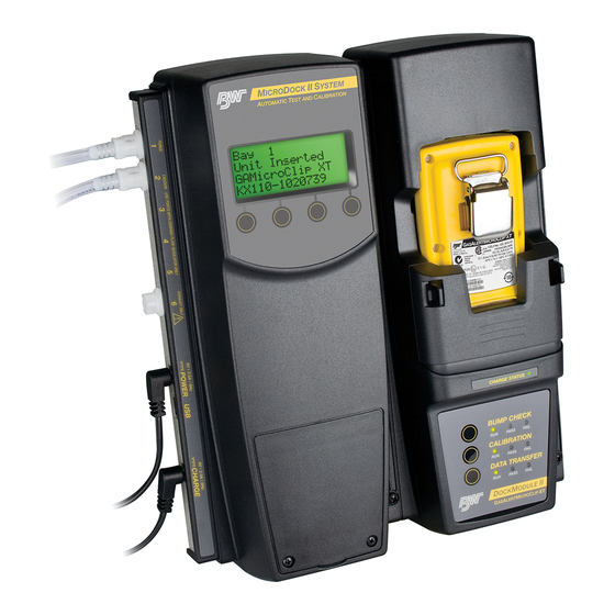
Page 16: Microdock Ii Base Station And Docking Modules
MicroDock II User Manual MicroDock II Base Station and Docking Modules Figure 1. MicroDock II Base Station and Docking Modules To connect additional docking modules and to correctly insert detectors into docking modules, refer to Installation. -
Page 17: Parts Of The Microdock Ii Base Station And Docking Module
MicroDock II MicroDock II Base Station and Docking Modules Parts of the MicroDock II Base Station and Docking Table 2. The MicroDock II Base Station and Docking Module Module Item Description Docking module lid Detector bay Charger status LED (optional) -
Page 18: Display Elements
MicroDock II User Manual Display Elements Pushbuttons Table 3. Display Elements Docking Module Pushbuttons Icon Description Table 4. Docking Module Pushbuttons AC power Pushbutton Description Batteries charged* To bump test a detector, press BUMP CHECK. Batteries half-charged* After connecting a new docking module,... -
Page 19: Base Station Pushbuttons
MicroDock II Pushbuttons Base Station Pushbuttons Table 5. Base Station Pushbuttons Item Description • Activate the base station • Select menu to access the user options • Select to scroll to different user options or to other functions/selections within a user option •... -
Page 20: Installation
MicroDock II User Manual Installation Table 6. Base Station Connections Item Description Inlet filter assembly (PURGE 1) C-cell batteries (4) Battery cover Phillips pan head retaining screws (2) MMC or SD card Battery compartment Charger port USB port Power port... -
Page 21: Battery Installation
MicroDock II Installation Battery Installation Note The base station can operate from either an electrical power a Warning source or batteries. The batteries will provide automatic Only change batteries in an atmosphere that is free of hazardous backup power if the main power fails. -
Page 22: Inserting The Gasalertclip Extreme And The Gasalert Extreme
MicroDock II User Manual Inserting the GasAlertClip Extreme and the GasAlert Table 7. Inserting the GasAlertClip Extreme and the GasAlert Extreme Extreme a Caution Item Description Alligator clip Infrared or intense ambient light (sun or halogen) may interfere with the base station/detector communication. - Page 23 MicroDock II Installation 5. Lower the lid and press down until the release tabs click. When the detector has been inserted correctly, the RUN LED(s) on the docking module lights yellow and the base station LCD displays the • the docking module number, •...
-
Page 24: Inserting The Gasalertmicro
MicroDock II User Manual Inserting the GasAlertMicro Table 8. Inserting the GasAlertMicro a Caution Item Description Infrared or intense ambient light (sun or halogen) may interfere Docking module lid with the base station/detector communication. Release tabs Detector bay Charge status indicator... - Page 25 MicroDock II Installation 11. Lower the lid and press down until the release tabs click. When the detector has been inserted correctly, the RUN LED(s) on the docking module lights yellow and the base station LCD displays the • the docking module number, •...
-
Page 26: Inserting The Gasalertmicro 5/Pid/Ir
MicroDock II User Manual Inserting the GasAlertMicro 5/PID/IR Note The GasAlertMicro 5, GasAlertMicro 5 PID, and GasAlertMicro 5 IR are referenced as the GasAlertMicro 5/PID/IR. The GasAlertMicro 5/PID/IR rechargeable battery pack can be charged separately from the detector. Refer to... -
Page 27: Inserting The Gasalertmicro 5/Pid/Ir
MicroDock II Installation 3. Press the two release tabs on the docking module and raise the Table 9. Inserting the GasAlertMicro 5/PID/IR lid. Item Description Important: If the GasAlertMicro 5/PID/IR detector is fitted with a Docking module lid pump, the diffusion adapter must be removed from the docking module lid. -
Page 28: Inserting The Gasalertmicro 5/Pid/Ir Battery Pack
MicroDock II User Manual 4. Hold the detector (serial number label down) at a 45° angle and Inserting the GasAlertMicro 5/PID/IR Battery Pack insert the bottom into the detector bay. To insert the lithium battery pack, refer to Figure 9. and the following pro- Ensure that the connector outlets on the bottom of the detector cedure. - Page 29 MicroDock II Installation 3. Hold the battery pack (serial number label down) at a 45° angle and insert the bottom into the detector bay. Ensure that the connector outlets on the bottom of the battery pack lock into place over the connector pins in the docking bay, and then lower the top into place.
-
Page 30: Inserting The Gasalertmicroclip
MicroDock II User Manual Inserting the GasAlertMicroClip Table 10. Inserting the GasAlertMicroClip a Caution Item Description Infrared or intense ambient light (sun or halogen) may interfere Module lid with the base station/detector communication. Release tabs Detector bay Alligator clip Charger status indicator... - Page 31 MicroDock II Installation 4. Lower the lid and press down until the release tabs click. When the detector has been inserted correctly, the RUN LED(s) on the docking module lights yellow and the base station LCD displays the • the docking module number, •...
-
Page 32: Inserting The Gasalertmax Xt
MicroDock II User Manual Inserting the GasAlertMax XT Table 11. Inserting the GasAlertMax XT a Caution Item Description Infrared or intense ambient light (sun or halogen) may interfere Detector pump with the base station/detector communication. Alligator clip Charge status Module lid... - Page 33 MicroDock II Installation Note The detector will briefly alarm when the pump connector is inserted. This is normal. The alarm will deactivate when the detector is properly inserted into the docking module. Ensure green is visible in the closed indicator. If it is not visible, the base station will not recognize the detector.
-
Page 34: Inserting The Gasalertquattro
MicroDock II User Manual Inserting the GasAlertQuattro Table 12. Inserting the GasAlertQuattro a Caution Item Description Infrared or intense ambient light (sun or halogen) may interfere GasAlertQuattro with the base station/detector communication. Charge status Connector pins Detector bay Module lid... -
Page 35: Inserting The Gasalertquattro Battery Pack
MicroDock II Installation 5. Close the lid and press until the release tabs click. Inserting the GasAlertQuattro Battery Pack When the detector has been inserted correctly, the RUN LED(s) To insert the GasAlertQuattro battery pack into the detector bay, refer to on the docking module lights yellow and the base station LCD Figure 13. - Page 36 MicroDock II User Manual 4. Insert the bottom of the battery pack (serial number label down) at a 30° angle into the detector bay and then lower the top into place. The docking module beeps and the Charge Status LED lights...
-
Page 37: Adding Another Docking Module
MicroDock II Adding Another Docking Module Adding Another Docking Module Table 14. Adding Another Docking Module If required, refer to Using the Base Station before adding a docking Item Description module. Phillips pan-head screw (3) a Warning End plate Only one module can be connected at a time. Complete steps #1- Barbed fitting ports 20 for each docking module that is added. - Page 38 MicroDock II User Manual Figure 14. Adding Another Docking Module (Front View)
- Page 39 MicroDock II Adding Another Docking Module Figure 15. Adding Another Docking Module (Back View)
- Page 40 MicroDock II User Manual Figure 16. Attaching Back Cover Plate (Back View)
-
Page 41: Initializing The New Docking Module
MicroDock II Adding Another Docking Module 1. Deactivate the base station. a Caution 2. Remove the power cord from the POWER port. If applicable, The base station must be deactivated after each module has been remove the charger cord from the CHARGER port. -
Page 42: Mounting The Microdock Ii
MicroDock II User Manual Mounting the MicroDock II The factory default pump speed displays beside Pump Setup. The base station pump speed is measured as a percentage (%) and the flow meter measures speed in ml/min. Note The base station is shipped with the factory default pump speed set to 350 ml/min. -
Page 43: Mounting The Microdock Ii
(41.7 mm) of space between each docking module. 3. Use four screws to attach the base station to the secure surface. Figure 18. Parts of the Wall Mounting Plate Table 15. Mounting the MicroDock II Item Description Wall mounting plate (2) -
Page 44: Changing Dip Switch Settings (Gasalertclip Extreme Only)
MicroDock II User Manual Changing Dip Switch Settings To change the dipswitch setting on a GasAlertClip Extreme docking (GasAlertClip Extreme module refer to Tables 15 and 16, Figures 16 and 17, and complete the only) following: The gas type for bump tests is defined by setting the dip switch within the 1. - Page 45 MicroDock II Changing Dip Switch Settings (GasAlertClip Extreme only) Note When reattaching the docking module, ensure the barbed tubing is inserted correctly. Ensure to correctly label the gas type on the docking module. Figure 19. Detaching the GasAlertClip Extreme Module...
- Page 46 MicroDock II User Manual Figure 20. Changing Dip Switch Settings...
-
Page 47: Using The Base Station
MicroDock II Using the Base Station Using the Base Station 2. Press and hold (the left most button) until the initializing screen displays. a Warning To prevent possible injury and/or property damage, only use the base station in a safe area that is free of hazardous gas, in an atmosphere of 20.9% oxygen. -
Page 48: Deactivating The Base Station
MicroDock II User Manual If a detector is inserted but not activated, the LCD displays the following Deactivating the Base Station message. To deactivate the base station, it must be in normal operation. From the normal operation screen, press and hold (the rightmost button) until Powering Down displays. -
Page 49: User Options Menu
MicroDock II User Options Menu User Options Menu Time/Date Time/Date adjusts the time (hour/minute), the date (month/day/year) The user options menu provides access to ten options. The following and the day of the week (1-7) of the base station. user options are listed in the order they are displayed on the base station LCD. -
Page 50: Inlet Setup
MicroDock II User Manual The cursor automatically displays below the first value of the a Warning month. Each value is selected, changed, and bypassed individu- Failed tests can result if the inlets are not setup correctly. ally. For initial base station activation, ensure the inlets are installed correctly as follows: •... -
Page 51: Gas Type
MicroDock II User Options Menu • Multi-gas Type Screen Continue to press to access the inlet 3, 4, and 5 screens. displays as the default gas type when each of the inlet screens are accessed for the first time. 4. To select a gas type, proceed to Type. - Page 52 MicroDock II User Manual Gas Type Gas Concentration Gas Type Gas Concentration (chlorine) bump only ppm and %LEL Custom 4-Gas ppm and %LEL HCN (hydrogen cyanide) Custom 3-gas ppm and %LEL S (hydrogen sulfide) Custom 2-Gas 3 – Gas SO...
-
Page 53: Gas Concentration Level
MicroDock II User Options Menu 7. To select a different gas type, press changes to 11. Press to move down to the gas concentration level. sel. indicate that the field is activated. Press to scroll through the list of gas types. -
Page 54: Gas Cylinder Lot # Field
MicroDock II User Manual Gas Cylinder Lot # Field Press sel to select the required gas. changes to the cursor automatically displays below the first value. Although this field is designed to enter the lot number of the correspond- ing gas cylinder, other types of data can be entered. A maximum of 14 characters (letters and/or numbers) can be selected. -
Page 55: Pump Setup
MicroDock II User Options Menu 20. Repeat step #19 for the remaining values. Contrast The following screen displays the corresponding lot number for Contrast brightens or darkens the LCD. To adjust the contrast level, the attached gas cylinder. complete the following: 1. -
Page 56: Backlight
MicroDock II User Manual 5. Press to scroll to another user option. 3. Press to scroll through the options. Enabled Press exit to return to the normal operation. Disabled Automatic auto Backlight Backlight enables, disables, or selects auto mode for the LCD lighting. -
Page 57: Formatting The Mmc/Sd Card
MicroDock II User Options Menu 3. Insert the MMC/SD card into the slot above the battery compart- Press sel to access the about base station screen. ment. If more than one docking module is connected to the base sta- tion, press to scroll to the additional docking module firmware revisions (M1 - M8). -
Page 58: Inlet Select
MicroDock II User Manual 5. Press sel to confirm the selection and to access the format- 7. Press to scroll to another user option. ting confirmation screen. Press exit to return to normal operation. For additional information about the MMC/SD card, refer to... -
Page 59: Pass Code
MicroDock II User Options Menu 2. Press sel to confirm the selection and access the field 1. From the user options menu, press to scroll to ( changes to the Pass Code option. 2. Press sel to select the option and access the field ( changes 3. -
Page 60: Entering User Options When Pass Code Protected
MicroDock II User Manual Language Entering User Options When Pass Code Protected To access the user options menu when the base station is pass code The base station provides five language options and can display all text protected, complete the following: on the LCD in the following languages: 1. -
Page 61: Results History
MicroDock II Results History Results History 3. Press to scroll to the different language options. The available options are The results history displays the results of the last ten bump tests or cali- • Eng (English), brations. • Fran (French), The newest results display first. - Page 62 MicroDock II User Manual Reconfiguring the Detector 7. The Load Configuration File dialog box displays. (not applicable to the GasAlertClip Extreme) Fleet Manager II can reconfigure the following detectors with the base station: • GasAlert Extreme • GasAlertMicro • GasAlertMicro 5/PID/IR •...
-
Page 63: Reconfiguring The Detector (Not Applicable To The Gasalertclip Extreme)
Press No to bypass reconfiguration and proceed to the bump 14. Select a MicroDock II to save to and click OK. test or calibration. 15. A dialog box displays the message Successfully saved 19. When the base station is reconfiguring the detector, the following MicroDock Configuration File. -
Page 64: Gas Conflicts
MicroDock II User Manual Gas Conflicts 20. Successful Reconfiguring: If reconfiguration is successful, the following screen displays. When performing a bump test or calibration, gas must be applied in a specific order to prevent gas conflicts that can damage the detector’s sensor(s). -
Page 65: Abort Option
MicroDock II Gas Conflicts If a gas conflict is detected by the base station, the gas conflicts screen 2. The conflicts/not found screen displays. automatically displays. 3. Press to scroll to the Abort Test option. Refer to the following sections, Conflicts Found. -
Page 66: Base Station Selects The Gas Inlet
MicroDock II User Manual Base Station Selects the Gas Inlet Note To resolve a conflict automatically, complete the following steps. sel is not pressed within 30 seconds, the base station automatically defaults to the inlet it has selected. 1. Press... -
Page 67: Not Found
MicroDock II Gas Conflicts Unsuccessful Conflict Resolution: If the conflict is not resolved by 2. Press to move to the gas that is in conflict. selecting a different inlet, refer to the following: • Ensure that the selected inlet is correct. -
Page 68: Accessing The Mmc/Sd Card During A Test
MicroDock II User Manual Accessing the MMC/SD Card During a Test The gases display. If an attempt is made to access the MMC/SD card on the base station from a PC while a bump test or calibration is being performed, the follow- ing screen displays. -
Page 69: Order Of Gases Applied For Bump Tests And Calibrations
MicroDock II Order of Gases Applied for Bump Tests and Calibrations Order of Gases Applied for Bump Tests and 5. Using Table 20., locate the corresponding rule number. Ensure that the desired order to apply gases corresponds to the gas Calibrations application rules. -
Page 70: Gas Type Application Table
MicroDock II User Manual Table 19. Gas Type Application Table COSH Gases S/CO) (Bump only) Quad gas quad gas - one step calibration Rule 4 Rule 11 quad gas - one step calibration Rule 5 Rule 11 Rule 9 Rules 8 &... -
Page 71: Gas Application Rules
MicroDock II Order of Gases Applied for Bump Tests and Calibrations Table 20. Gas Application Rules Rule # Gas Type Apply Exception(s) Two exceptions: NO and O First Three exceptions: PH and ClO First First Three exceptions: HCN Last One exception: PID... -
Page 72: Bump Test
MicroDock II User Manual Bump Test To perform a bump test, complete the following: 1. Ensure the MMC/SD card is inserted if datalogging is required. A bump test is performed to confirm that the detector is responding to gas, and that the audio and visual alarms are operational. - Page 73 MicroDock II Bump Test 5. Depending upon the type of detector, the option to reconfigure is 6. The base station begins the bump test and displays the provided. • docking module number, If the detector was reconfigured without user’s consent, the fol- •...
- Page 74 MicroDock II User Manual If there are no gas conflicts, the base station then applies the For more information, refer to Automatic Datalog Download gas. (GasAlertMicroClip, GasAlertMax XT, and GasAlertQuattro only). If more than one gas is being applied, the base station performs 8.
-
Page 75: Bump Test Results
MicroDock II Bump Test Bump Test Results Bump Fail After the bump test is complete, the base station displays the results of the test. Pass If the detector failed a bump test, displays beside the applicable gas Fail Example: H2S... -
Page 76: Incorrect Inlet Setup
MicroDock II User Manual Incorrect Inlet Setup Sensor Disabled a Warning If an inlet is not setup correctly, a hyphen ( ) displays beside the gas type. To prevent personal injury and/or property damage, enable or replace the sensor immediately. Refer to the corresponding detector user manual or technical reference guide for sensor replacement procedures. -
Page 77: Calibration
MicroDock II Calibration Calibration HCN: 5 to 20 ppm balance N ETO: 5 to 50 ppm balance N NO: 10 to 250 ppm balance N Guidelines : 3 to 25 ppm (for bump checks only) a Caution VOC: 100 ppm isobutylene : 5000 ppm balance air or 0-5.0 % v/v CO... -
Page 78: Calibration Procedure (All Models Excluding The Gasalertclip Extreme)
MicroDock II User Manual • Calibrate the sensor if the ambient gas readings vary during The following detectors transfer event logs to the base station MMC dur- startup. ing a calibration: • Calibrate a new sensor before use. Allow the sensor to stabilize •... -
Page 79: Gasalertmicro 5 Ir With Co 2 Sensor
MicroDock II Calibration The base station begins the calibration and displays the If more than one gas is being applied, the base station performs a purge between each gas. Depending upon the gas type, the • docking module, purge time(s) will vary. -
Page 80: Calibration Results
MicroDock II User Manual 3. The base station purges the N before applying the CO gas. Calibration Results After the calibration is complete, the base station LCD displays the results. Pass 4. The base station then applies the gas to the CO sensor. -
Page 81: Incorrect Inlet Setup
MicroDock II Calibration Incorrect Inlet Setup Sensor Disabled a Warning If an inlet is not setup correctly during a calibration, the base station dis- plays Fail and a hyphen ( ) beside the gas type. To prevent personal injury and/or property damage, enable or replace the sensor immediately. -
Page 82: Data Transfer (Gasalert Extreme, Gasalertmicroclip, Gasalertmax Xt, And Gasalertquattro Only)
MicroDock II User Manual Data Transfer If a failure occurs during the transfer of a datalog, typically some (GasAlert Extreme, GasAlertMicroClip, GasAlert- of the data transfers to the MMC/SD card. To determine if any Max XT, and GasAlertQuattro only) data has been transferred, access the MMC data using Fleet Manager II. -
Page 83: Maximum Datalog Storage Capacity
Pass to return to the normal oper- Using the MicroDock II ating screen. To enable Automatic Datalog Download using MicroDock II and Fleet Manager II, complete the following: Maximum Datalog Storage Capacity 1. From the PC, open Fleet Manager II. - Page 84 MicroDock II’s clock. • Automatically reprogram (including Date/Time): When selected, the detector is automatically reconfig- ured when a bump test or calibration is initiated. The detector’s clock is changed to match the MicroDock II’s clock. Figure 24. Save to MicroDock(s) Dialog Box...
-
Page 85: Base Station Mmc/Sd Card
MicroDock II Base Station MMC/SD Card Base Station MMC/SD Card 12. Select a MicroDock II to save the configuration file and click OK. The following dialog box displays. Event Logging Bump tests and calibrations are recorded on a MultiMediaCard (MMC) or a Secure Digital (SD) card. -
Page 86: Inserting/Replacing A Mmc/Sd Card
Data that is saved on the MMC/SD card can be transferred to a PC. MicroDock II test results are saved in the .CSV format. PC Requirements The following version of the Microsoft Windows operating system sup- ports Fleet Manager II: •... -
Page 87: Charging The Battery Pack (Excluding Gasalert Extreme And Gasalertclip Extreme)
MicroDock II Charging the Battery Pack (Excluding GasAlert Extreme and GasAlertClip Extreme) Charging the Battery Pack Charger/Battery Pack Guidelines (Excluding GasAlert Extreme and GasAlertClip Extreme) • Deactivate the detector before charging. • When charging is complete, the detector can remain in the a Warning detector bay without wear or damage to the battery. -
Page 88: Charging Procedure
MicroDock II User Manual GasAlertMicro 5/PID/IR or GasAlertMicro has completed charg- CHARGE STATUS LED briefly lights red then green during the ing before beginning to charge. self-test. The LED then deactivates. • If another GasAlertMicro 5/PID/IR or GasAlertMicro is added, the 2. -
Page 89: Maintenance
MicroDock II Maintenance Maintenance Battery Pack Storage GasAlertMicro and GasAlertMicro 5/PID/IR a Warning When storing for extended periods of time, ensure that the detector is No user-serviceable parts inside. fully charged and recharged every 30 days. To maintain the base station in good operating condition, perform the fol- lowing basic maintenance as required. -
Page 90: Troubleshooting
MicroDock II User Manual Troubleshooting If a problem is encountered, refer to the solutions provided in the following table. If the problem cannot be resolved, contact BW Technologies by Hon- eywell. Table 22. Troubleshooting Tips Problem Possible Cause Solution There is no power connection. - Page 91 MicroDock II Troubleshooting Problem Possible Cause Solution Oxygen alarm setpoints of the detector are Connect a quad-gas cylinder that set to the same concentration level as the has 18% O gas cylinder. The oxygen sensor fails a bump test. Ambient air (inlet 1) is blocked or the inlet Remove the blockage or replace the inlet filter is contaminated.
- Page 92 MicroDock II User Manual Problem Possible Cause Solution Detector is deactivated. Activate the detector. Detector does not have IR communication Refer to the label located on the back of the capabilities. detector for IR capabilities. Firmware of the detector requires an...
- Page 93 MicroDock II Troubleshooting Problem Possible Cause Solution The charger LED does not light when the Detector or battery pack is not inserted into Firmly insert the detector into the detector detector or battery pack is inserted (for the detector bay correctly.
- Page 94 No drive letter is created for the Windows XP is not correctly mapping the click Disk Management. MicroDock II (Windows XP) on the PC. drive. 3) In the list of drives in the right pane, right- click the new drive and then click Change Drive Letter and Path(s).
- Page 95 MicroDock II Troubleshooting Problem Possible Cause Solution Disable Autoplay. Windows XP: 1) Click Start Menu, then Run. 2) Enter gpedit.msc 3) The Group Policy window displays. 4) Click Administrative Templates and then System. 5) In the right-hand pane, double-click on Turn off Autoplay.
- Page 96 Charge the detector battery if too low. Non-datalogger detector is inserted Insert only datalogger models. in the docking module. If an error code displays on the LCD, record Software exception. it and contact BW Technologies by Honey- well.
-
Page 97: Replacement Parts And Accessories
Network USB communication device Table 23. Replacement Parts and Accessories DOCK2-MMC Delkin 128 MB MultiMediaCard (MMC) Model Number Description Wall Mount Adapters GasAlertMicro Docking Module For MicroDock II and charging modules WMA-DOCK DOCK2-0-1A-00-N Non-charging (kit of 2) DOCK2-0-1B1C-00-N Charging (power supply included) MK-CG2-34B... -
Page 98: Specifications
User Manual Specifications Configuration recognition: Automatic (instrument and sensor) Alarm/calibration parameters: User-defined The MicroDock II is for indoor use only. Calibration gas connections: Built-in (base station) Instrument dimensions: 21.2 x 26.3 x 8.2 cm Gas connection: 1/8" SMC connect sub-miniature coupling (8.3 x 10.4 x 3.2 in.) base station and one docking module... -
Page 99: Charger Specifications
MicroDock II Specifications Charger Specifications This equipment has been tested and found to comply with the limits for a Class A digital device, pursuant to Part 15 of the FCC Rules and ICES- Size: 8.6 x 8.2 x 7.8 cm (3.4 x 3.2 x 3.1 in.) 003 Canadian EMI requirements. - Page 100 130460 D5617/8 [English] © BW Technologies 2009. All rights reserved.
Need help?
Do you have a question about the MicroDock II and is the answer not in the manual?
Questions and answers