Simrad GO XSE Operator's Manual
Hide thumbs
Also See for GO XSE:
- Operator's manual (162 pages) ,
- Installation manual (84 pages) ,
- Getting started (41 pages)
Table of Contents
Advertisement
Quick Links
Download this manual
See also:
Installation Manual
Advertisement
Table of Contents

Related Manuals for Simrad GO XSE


Summary of Contents for Simrad GO XSE
- Page 1 GO XSE Operator Manual ENGLISH www.simrad-yachting.com...
- Page 3 Fishing Hot Spots Inc. Copyright© 2012 Fishing Hot Spots. ™ ™ FUSION-Link Marine Entertainment Standard is a registered trademark of FUSION Electronics Ltd. ® C-MAP is a registered trademark of C-MAP. Preface | GO XSE Operator Manual...
- Page 4 Part 15 of the FCC Rules. Operation is subject to the following two conditions: (1) this device may not cause harmful interference, and (2) this device must accept any interference received, including interference that may cause undesired operation. Preface | GO XSE Operator Manual...
-
Page 5: About This Manual
If you are unsure, contact your service provider to confirm rates and restrictions. About this manual This manual is a reference guide for operating GO XSE units. It assumes that all equipment is installed and configured, and that the system is ready to use. - Page 6 Drag finger on the screen in any direction. • Zoom In/Out Select the relevant panel button. Touch operation: Use pinch or spread gestures. • Exit the PDF viewer Select the X in the upper right corner of the panel. Preface | GO XSE Operator Manual...
- Page 7 The software version currently on this unit can be found in the About dialog. The About dialog is available in the System Settings. For information regarding upgrading your software, refer to "Software upgrades" on page 188. Preface | GO XSE Operator Manual...
- Page 8 Preface | GO XSE Operator Manual...
-
Page 9: Table Of Contents
Setting the appearance of the Instrument bar 33 Charts The Chart panel Chart data Showing dual chart types Vessel symbol Chart scale Panning the chart Positioning the vessel on the chart panel Displaying information about chart items Contents | GO XSE Operator Manual... - Page 10 Estimated fuel range ring Fuel gauge Tide gauge View trip recordings 75 Autopilot Safe operation with the autopilot Activating the autopilot Switching from automatic mode to manual steering Autopilot indication on the pages The Autopilot panel Contents | GO XSE Operator Manual...
- Page 11 115 Zooming the image 115 Using the cursor on the image 116 Saving waypoints 116 Viewing history 117 Setting up the image 119 Advanced options 119 Start recording log data 121 Stop recording log data Contents | GO XSE Operator Manual...
- Page 12 143 Connect and disconnect from a wireless hotspot 144 GoFree Shop 144 GoFree Link 146 Uploading log files to Insight Genesis 146 Wireless settings 149 AIS 149 AIS target symbols 150 Viewing information about AIS targets Contents | GO XSE Operator Manual...
- Page 13 179 The Time plot panel 179 Selecting data 180 Alarms 180 Alarm system 180 Type of messages 180 Single alarms 180 Multiple alarms 181 Acknowledging a message 181 Alarms dialog 183 Tools 183 Waypoints/routes/tracks 183 Tides 183 Alarms Contents | GO XSE Operator Manual...
- Page 14 187 Advanced simulator settings 188 Maintenance 188 Preventive maintenance 188 Cleaning the display unit 188 Cleaning the media port door 188 Checking the connectors 188 Software upgrades 190 Backing up your system data 193 Touchscreen operation Contents | GO XSE Operator Manual...
-
Page 15: Introduction
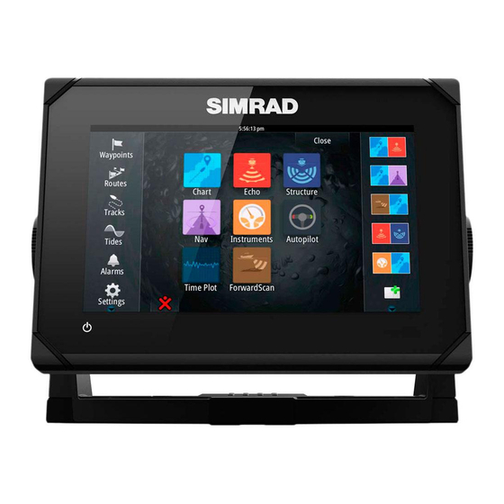
Select to exit the Home page and return to the previous active page. Favorites Select a button to display the panel combination. Press and hold a favorite button to enter edit mode for the Favorites panel. Introduction | GO XSE Operator Manual... -
Page 16: Application Pages
Status bar Dialog Information to or input from the user. Control bar Select a feature button to display controls for it. Alarm message Displayed if dangerous situations or system faults occur. Introduction | GO XSE Operator Manual... - Page 17 Ú Note: The number of pre-configured split pages cannot be changed, and the pages cannot be customized or deleted. Access a pre-configured split page by pressing and holding the main panel button. Introduction | GO XSE Operator Manual...
-
Page 18: Integration Of 3 Rd Party Devices
For more information, refer to "Adding new favorite pages" on page 28. Integration of 3 party devices Several 3 party devices can be connected to the GO XSE. The applications are displayed on separate panels or integrated with other panels. A device connected to the NMEA 2000 network should automatically be identified by the system. - Page 19 Refer to "Audio" on page 159 for more information. BEP CZone integration The GO XSE integrates with BEP’s CZone system used for controlling and monitoring a distributed power system on your vessel. The CZone icon is available in the Tools panel on the Home page when a CZone system is available on the network.
-
Page 20: Feature Unlock
You can connect a remote controller to the network and remotely control the unit. To find out which remote controllers can be used, refer to the product web page at: www.simrad-yachting.com. A separate manual is included with the remote controller. Introduction | GO XSE Operator Manual... -
Page 21: Basic Operation
First time startup When the unit is started for the first time, or after a factory default, the unit displays a setup wizard. Respond to the setup wizard prompts to select some fundamental setup options. Basic operation | GO XSE Operator Manual... -
Page 22: Display Illumination
This feature is also useful when cleaning the screen while the unit is turned on. You lock the touchscreen from the System Controls dialog. Basic operation | GO XSE Operator Manual... -
Page 23: Instrument Bar
Select a full page panel by selecting the relevant application button on the Home page • Select a favorite page by selecting the relevant favorite button • Select a predefined split panel by pressing and holding the relevant application icon Basic operation | GO XSE Operator Manual... -
Page 24: Displaying The Favorites Panel As A Pop-Up On A Page
Select the MOB waypoint to activate it Select the MOB waypoint's pop-up to display the MOB waypoint dialog Select the delete option in the dialog. A MOB waypoint can also be deleted from the menu when it is activated. Basic operation | GO XSE Operator Manual... -
Page 25: Screen Capture
When the function is activated, you can take a screenshot on a touch screen by double-selecting the title bar of an open dialog, or by double-selecting the status bar if no dialog is open. To view files, refer to "Files" on page 184. Basic operation | GO XSE Operator Manual... -
Page 26: Customizing Your System
Select the adjust splits option in the dialog Adjust the panel size by dragging the adjustment icon Confirm your changes by tapping one of the panels or selecting the save option in the menu. Customizing your system | GO XSE Operator Manual... -
Page 27: Customizing The Long Press Feature
After the correct PIN code is entered, all of them can be accessed without re-entering the PIN code. • Settings, activated from the Tools panel or System Controls dialog Customizing your system | GO XSE Operator Manual... -
Page 28: Adding New Favorite Pages
Change the panel arrangement (only possible for 2 or 3 panels), if required Save the page layout. The system displays the new favorite page, and the new page is included in the list of favorite pages on the Home page. Customizing your system | GO XSE Operator Manual... -
Page 29: Edit Favorite Pages
You can specify the information displayed in the instrument bars. You can turn the Instrument bar off from the System controls dialog. Ú Note: This only turns the Instrument bar off for the current page. Customizing your system | GO XSE Operator Manual... - Page 30 (Chart, Radar, Echo, Nav, and so on). Select the predefined Fuel activity bar or change a gauge source to Fuel Economy. To change a gauge source, refer to "Setting the appearance of the Instrument bar" on page 29. Customizing your system | GO XSE Operator Manual...
- Page 31 Fuel settings dialog. You can reset your average fuel economy from the Reset Fuel Economy button on the Fuel settings dialog. When you reset it, the system starts calculating the new average. Customizing your system | GO XSE Operator Manual...
- Page 32 Set the measurement units for the fuel economy gauge in the Economy field in the Units settings dialog. Customizing your system | GO XSE Operator Manual...
-
Page 33: Charts
Range rings* Track* Chart range scale Range rings interval (only displayed when Range rings are turned on) * Optional chart items. You turn the optional chart items on/off individually from the Chart settings dialog. Charts | GO XSE Operator Manual... -
Page 34: Chart Data
You can select a dual chart panel by pressing and holding the Chart application button on the Home page, or by creating a favorite page with two chart panels. Charts | GO XSE Operator Manual... -
Page 35: Vessel Symbol
Positioning the vessel on the chart panel Chart orientation Several options are available for how the chart is rotated in the panel. The chart orientation symbol in the panel’s upper right corner indicates the north direction. Charts | GO XSE Operator Manual... -
Page 36: Displaying Information About Chart Items
(photos) associated with the location or object. Ú Note: Pop-up information has to be enabled in chart settings to see basic item information. Charts | GO XSE Operator Manual... -
Page 37: Using The Cursor On The Chart Panel
Without removing your finger from the screen, drag the selection circle to the desired position. When you remove your finger from the screen the cursor reverts to normal cursor operation. Charts | GO XSE Operator Manual... -
Page 38: Measuring Distance
In the Chart and Nav panels, you can save a waypoint at the vessel position, when the cursor is not active, by selecting the new waypoint option in the menu. Charts | GO XSE Operator Manual... -
Page 39: Creating Routes
All chart types work in 3D mode, but without 3D cartography for the appropriate area the chart appears flat. When the 3D chart option is selected, the Pan and the Rotate icons appear on the chart panel. Charts | GO XSE Operator Manual... -
Page 40: Chart Overlay
Information about the overlay data are described in more detail in separate sections in this manual. Insight and C-MAP charts All possible menu options for Insight and C-MAP charts are described below. The features and menu options available can vary Charts | GO XSE Operator Manual... - Page 41 (equal to or less than 1 knot), depending on the current in that location. If there is no current (0 knots) this will be shown as a white, square icon. Static Current and Tide icons Dynamic Current icons Charts | GO XSE Operator Manual...
- Page 42 Orientation, Look ahead, 3D, and change Chart source (previously described in this section) are common for all chart types. Presentation The charts can be displayed in different imagery styles. Shaded relief No contours Raster imagery High resolution bathymetry Charts | GO XSE Operator Manual...
- Page 43 Insight and C-MAP chart categories Insight and C-MAP charts include several categories and sub- categories that you can turn on/off individually depending on which information you want to see. Charts | GO XSE Operator Manual...
- Page 44 Photo overlay, land only Full Photo overlay Photo transparency The Photo transparency sets the opaqueness of the photo overlay. With minimum transparency settings the chart details are almost hidden by the photo. Minimum transparency Transparency at 80 Charts | GO XSE Operator Manual...
- Page 45 Depth 1 and Depth 2 Depth presets that shade different depths in different colors. Custom You can adjust the depth threshold, color and opacity (transparency) of color shading for Depth 1 and Depth 2. Charts | GO XSE Operator Manual...
-
Page 46: Navionics Charts
You can also get a message if you try to use a restricted feature when the Navionics chart card is not activated. To activate the card, contact Navionics. Charts | GO XSE Operator Manual... -
Page 47: Navionics Specific Chart Options
SCL History Ú Note: If no active Navionics chart subscription is found, the SonarChart Live menu option changes to SCL History. Select to display previously recorded data on the chart overlay. Charts | GO XSE Operator Manual... -
Page 48: Navionics View Options
Ú Note: All numeric values are shown in the relevant system units (unit of measurement) set by user. Charts | GO XSE Operator Manual... - Page 49 The Photo transparency sets the opaqueness of the photo overlay. With minimum transparency settings the chart details are almost hidden by the photo. Minimum transparency Maximum transparency SonarChart The system supports the Navionics SonarChart feature. Charts | GO XSE Operator Manual...
- Page 50 Highlights areas of shallow water. This allows you to highlight areas of water between 0 and the selected depth (up to 10 meters/30 feet). No shallow water highlighted Shallow water highlight: 0 m - 3 m Charts | GO XSE Operator Manual...
-
Page 51: Navionics Chart Settings
Rock filter level Hides rock identification on the chart beneath a given depth. This helps you to declutter charts in areas where there are many rocks located at depths well below your vessel's draught. Charts | GO XSE Operator Manual... -
Page 52: Chart Settings
U.S. territorial waters. Range Rings The range rings can be used to present the distance from your vessel to other chart objects. The range scale is set automatically by the system to suit the chart scale. Charts | GO XSE Operator Manual... - Page 53 SonarChart Live as the sonar is recorded. Synchronize 2D/3D chart Links the position shown on one chart with the position shown on the other chart when a 2D and a 3D chart are shown side by side. Charts | GO XSE Operator Manual...
- Page 54 Turns on/off viewing of longitude and latitude grid lines on the chart. Waypoints, Routes, Tracks Turns on/off displaying of these items on chart panels. Also opens the Waypoints, Routes and Tracks dialogs you can use to manage them. Charts | GO XSE Operator Manual...
-
Page 55: Waypoints, Routes, And Tracks
Activate the menu and select the waypoint in the menu Select the move option Select the new waypoint position Select Finish in the menu. The waypoint is now automatically saved at the new position. Waypoints, Routes, and Tracks | GO XSE Operator Manual... - Page 56 The waypoint radius alarm must be toggled ON in the alarm dialog to activate an alarm when your vessel comes within the defined radius. For more information, refer to "Alarms dialog" on page 181. Waypoints, Routes, and Tracks | GO XSE Operator Manual...
-
Page 57: Routes
Delete a route You can delete a route by selecting the Delete menu option when the route is activated. You can also delete routes from the Routes tool on the Home page. Waypoints, Routes, and Tracks | GO XSE Operator Manual... - Page 58 Navionics uses red (unsafe) and green (safe), while C-MAP uses red (unsafe), yellow (dangerous) and green (safe). Move any routepoints if required when the route is in preview mode. Select Keep to accept the routepoints positions. Waypoints, Routes, and Tracks | GO XSE Operator Manual...
- Page 59 Entire route option used when first and last route points are • selected. First and last routepoint Result after automatic routing Selection option used for autorouting part of a route. • Two routepoints selected Result after automatic routing Waypoints, Routes, and Tracks | GO XSE Operator Manual...
- Page 60 The Edit Tracks dialog can also be accessed by selecting the Tracks tool on the Home page. Waypoints, Routes, and Tracks | GO XSE Operator Manual...
-
Page 61: Tracks
The automatic tracking function can be turned off from the Tracks dialog. Creating new Tracks You can start a new track from the Tracks dialog, activated by using the Tracks tool on the Home page. Waypoints, Routes, and Tracks | GO XSE Operator Manual... -
Page 62: Waypoints, Routes, And Tracks Dialogs
Waypoints, Routes, and Tracks dialogs The Waypoints, Routes, and Tracks dialogs give access to advanced edit functions and settings for these items. The dialogs are accessed from the Tools panel on the Home page. Waypoints, Routes, and Tracks | GO XSE Operator Manual... - Page 63 Waypoints, Routes, and Tracks | GO XSE Operator Manual...
-
Page 64: Navigating
The Nav panels can be used to display information when you are navigating. The Nav panel The Nav panel is activated from the Home page, either as a full page panel or as part of a multiple panel page. Data fields Route information Vessel heading Navigating | GO XSE Operator Manual... - Page 65 You toggle between the panels by selecting the left or right arrow symbols, or by using the arrow keys. GPS position info Loran position info Navigating | GO XSE Operator Manual...
-
Page 66: Navigate To Cursor Position
If you choose not to engage the autopilot or if your boat is set to SAIL, the autopilot can be set to navigation mode from the Autopilot Controller later on. For more information about autopilot functionality, refer to "Autopilot" on page 75. Navigating | GO XSE Operator Manual... -
Page 67: Navigation Settings
The vessel is considered arrived at the waypoint when it is within this radius. XTE limit This setting defines how far the vessel can deviate from the selected route, if the vessel goes beyond this limit, an alarm is activated. Navigating | GO XSE Operator Manual... -
Page 68: Arrival Alarm
Datum Most paper charts are made in the WGS84 format, which also is used by the GO XSE. If your paper charts are in a different format, you can change the datum settings accordingly to match your paper charts. -
Page 69: Tripintel
Select the TripIntel button on the Tool panel to display the TripIntel page. Current trip statistics The Information tab on the TripIntel page shows current trip statistics: • Distance traveled • Time traveled • Average speed • Maximum speed • Fuel economy • Fuel used TripIntel | GO XSE Operator Manual... -
Page 70: Automatic Trip Recording
Long-term statistics Select Long Term Statistics to view seasonal trip information such as engine running hours, total distance traveled, and fuel economy. TripIntel | GO XSE Operator Manual... -
Page 71: Estimated Fuel Range Ring
The Estimated fuel range ring is calculated from the Vessel Fuel Remaining only, not level sensors. When recording your refueling, you must 'Set to full' or 'Add fuel' for the range ring to be accurate. TripIntel | GO XSE Operator Manual... -
Page 72: Fuel Gauge
Tide stations on Chart cards provide tide information. Select the Tide button to view tide graphs and specify which Tide station provides tide information. If no tide station is chosen, tide information from the nearest tide station is used. TripIntel | GO XSE Operator Manual... -
Page 73: View Trip Recordings
History list and then select the name in the Trip History details dialog. This opens the Trip name dialog where you can change the trip name. TripIntel | GO XSE Operator Manual... - Page 74 TripIntel | GO XSE Operator Manual...
-
Page 75: Autopilot
Autopilot controller or using a physical standby key. Ú Note: If the unit is connected to an EVC system via the SG05, you can take manual control of the steering regardless of the Autopilot | GO XSE Operator Manual... -
Page 76: Autopilot Indication On The Pages 77 The Autopilot Panel
Select Autopilot in the Control bar to activate the Autopilot controller. The Autopilot controller has a fixed position on the left-side of the page. Close the Autopilot controller by selecting Close/Back on the Autopilot controller. Autopilot | GO XSE Operator Manual... - Page 77 To make the autopilot panel available, activate the show autopilot features option in the Advanced, Features section of the System Settings dialog. The number of data fields included in the autopilot panel is dependent on available panel size. Autopilot | GO XSE Operator Manual...
-
Page 78: Autopilot Modes
Autopilot controller to control the rudder. The rudder will move as long as the button is pressed. • Activate NFU mode by selecting the port or starboard arrow button in the Autopilot controller when the autopilot is in Standby or FU mode. Autopilot | GO XSE Operator Manual... -
Page 79: Follow-Up Steering (Fu)
When the vessel is turning in AUTO mode, an instant reset of the mode activates the heading capture function. This automatically cancels the turn, and the vessel continues on the heading read from the compass the very moment you re-activated the mode. Autopilot | GO XSE Operator Manual... -
Page 80: Nodrift Mode
NoDrift mode. Dodging If you need to avoid an obstacle when using NoDrift mode, you can set the autopilot to Standby mode and power steer or use the helm until the obstacle is passed. Autopilot | GO XSE Operator Manual... -
Page 81: Nav Mode
Ú Note: To obtain satisfactory navigation steering, the GO XSE must have valid position input. Autosteering must be tested and determined satisfactory prior to entering the NAV mode. - Page 82 Example: With the speed of 20 knots you should use a waypoint circle with radius 0.09 Nm. Ú Note: The distance between any waypoints in a route must not be smaller than the radius of the waypoint arrival circle. Autopilot | GO XSE Operator Manual...
-
Page 83: Wind Mode
The tack time is also controlled by the speed of the boat to prevent loss of speed during a tack. You can initiate the tack function from WIND mode. Autopilot | GO XSE Operator Manual... -
Page 84: Turn Pattern Steering
U-Turn changes the current set heading to be 180° in the opposite direction. The turn rate is identical to Rate limit settings. This cannot be changed during the turn. Ú Note: Refer to the separate GO XSE Installation manual for information about Rate limit settings. Autopilot | GO XSE Operator Manual... - Page 85 Makes the vessel yaw around the main heading. During the turn you can alter the heading change and the turn radius. Depth contour tracking, DCT If the system has Echosounder input, the autopilot can be set to follow a depth contour. Autopilot | GO XSE Operator Manual...
- Page 86 Port option Starboard option (depth decreases to port) (depth decreases to starboard) The following parameters are available for depth contour tracking: Depth gain Autopilot | GO XSE Operator Manual...
-
Page 87: Using The Autopilot In An Evc System
Using the autopilot in an EVC system When the GO XSE is connected to an EVC system via the SG05, you can take manual control of the steering regardless of the autopilot mode. - Page 88 A high response level increases the rudder activity and provides more tight steering. Too high a response level will cause the boat to make S movements. Autopilot | GO XSE Operator Manual...
- Page 89 If the value is set too high the overshoot will increase and the steering will be unstable. Autopilot | GO XSE Operator Manual...
- Page 90 Course change confirm angle: Defines the limits for course change to next waypoint in a route. If the course change is more than this set limit, you are prompted to verify that the upcoming course change is acceptable. Autopilot | GO XSE Operator Manual...
- Page 91 • Manual speed: If neither boat speed or SOG data is available and or deemed reliable a manual value for speed source can be entered and used by the autopilot to aid steering calculations Autopilot | GO XSE Operator Manual...
-
Page 92: Radar
For more information, see "Chart overlay" on page 40. Ú Note: Radar overlay requires data from a heading sensor or compass to ensure proper orientation with the chart. The radar panel Range Orientation Motion Compass* Heading line* Rotary controls Radar | GO XSE Operator Manual... -
Page 93: Dual Radar
The 3-digit radar source number is the last 3 digits of the radar's serial number. Radar overlay You can overlay the Radar image on the Chart. This can help you to easily interpret the radar image by correlating the radar targets with charted objects. Radar | GO XSE Operator Manual... -
Page 94: Radar Operational Modes
Ú Note: The blue accent pedestal lighting might not be approved for use in your boating location. Check your local boating regulations before turning the blue accent lights ON. Radar | GO XSE Operator Manual... -
Page 95: Radar Range
When you position the cursor on the radar panel, the cursor position window is activated and the cursor menu options are displayed. To remove the cursor and cursor elements from the panel, select Clear cursor or press the X key. Radar | GO XSE Operator Manual... -
Page 96: Saving Waypoints
You can define up to four sectors on the PPI inside which no radar data is transmitted. This enables you to blank-out interference caused by features on your boat or from a secondary radar. The Radar | GO XSE Operator Manual... -
Page 97: Adjusting The Radar Image
Weather - In this mode the radar settings are optimized for best • detection and presentation of rain clutter. Image update rate is slowed and color depth is increased. Radar | GO XSE Operator Manual... - Page 98 Bird: OFF Noise Rejection Fast scan Custom: Adjustable Custom: Adjustable Harbor: Medium Harbor: High Offshore: High Offshore: High Weather: Medium Weather: OFF Bird: High Bird: OFF * Maximum range is dependent on antenna length. Radar | GO XSE Operator Manual...
- Page 99 If the gain is set too high, the image might be cluttered with background noise. Gain has a manual and an automatic mode. You toggle between automatic and manual mode in the slide bar. Radar | GO XSE Operator Manual...
-
Page 100: Advanced Radar Options
Radar, transmit on one range only, set the Noise Reject control to High and the threshold as low as possible. The default is 30% for less clutter on the screen. If OFF is selected for the GO XSE, the range performance is about equal to 3G radar. In some areas where extreme high interference may exist, try OFF for best radar image. - Page 101 Sea State Set the Sea State control according to current sea conditions for best sea clutter rejection. Target boost (3G and 4G Broadband, and Pulse Radar only) Radar | GO XSE Operator Manual...
-
Page 102: Radar View Options
- Black/Red palette - Yellow - White/Red palette - Yellow - Black/Green palette - Red - Black/Yellow palette - Red Radar overlay palettes on charts • Diverging targets are dark grey. • Approaching targets are yellow. Radar | GO XSE Operator Manual... - Page 103 Examples of how VelocityTrack behaves in 2 navigation scenarios is illustrated below. The illustrations show a target (A) crossing own vessel's (B) path. 0° 0° The examples show the target movement (1-5) over 5 radar scans with the radar in relative motion mode. Radar | GO XSE Operator Manual...
- Page 104 Different colors (palettes) can be used to represent detail on your radar panel. Radar orientation Radar orientation is indicated on the upper left corner of the radar panel as either HU (Heading UP), NU (North Up) or CU (Course up). Radar | GO XSE Operator Manual...
- Page 105 In Relative motion your vessel remains in a fixed location on the Radar PPI, and all other objects move relative to your position. You select the position of the fixed location as described in "Offsetting the PPI center" on page 106. Radar | GO XSE Operator Manual...
- Page 106 Offsetting the PPI center is allowed only in Relative motion. PPI center: Center PPI center: Look Ahead PPI Center: Offset You return the antenna center to PPI center by using the offset option in the View menu. Radar | GO XSE Operator Manual...
-
Page 107: Ebl/Vrm Markers
When positioned, you can turn the EBL/VRM on/off by selecting the relevant markers on the data bar, or by deselecting the marker from the menu. Defining an EBL/VRM marker Ensure that the cursor is not active Radar | GO XSE Operator Manual... -
Page 108: Setting A Guard Zone Around Your Vessel
Select Adjust to define the settings for the guard zone. The values can be set from the menu or by dragging on the radar panel. - A: Bearing, relative to the vessel heading - B: Depth Radar | GO XSE Operator Manual... -
Page 109: Marpa Targets
MARPA tracking is an important tool for collision avoidance. Ú Note: MARPA requires heading data for both the radar and the GO XSE. MARPA target symbols The system uses the target symbols shown below. Radar | GO XSE Operator Manual... - Page 110 Viewing MARPA target information If the pop-up is activated, you can select a MARPA target to display basic target information. Information for the 3 MARPA targets closest to the vessel is also displayed in the data bar. Radar | GO XSE Operator Manual...
-
Page 111: Recording Radar Data
MARPA to work (valid GPS position and heading sensor connected to the radar server). Recording radar data You can record radar data and save the file internally in the GO XSE unit, or save it onto a memory card inserted into the unit’s card reader. -
Page 112: Radar Settings
You can define the length of the MARPA trail making it easier to follow target movement. A circle can be added around your vessel to present the danger zone. The radius of the ring is the same as the closest point of Radar | GO XSE Operator Manual... - Page 113 156. An alarm triggers if a vessel is tracking into your safe zone. Installation The Installation option is used for radar installation, described in the separate Radar or GO XSE Installation manuals. Radar | GO XSE Operator Manual...
-
Page 114: Echosounder
The Echosounder image Depth Temperature Frequency and Zoom scale Bottom Zoom buttons Depth range scale Instrument panel Zoom column Fish arches Echosounder | GO XSE Operator Manual... -
Page 115: Zooming The Image
Activate the cursor on the panel, then press and hold your finger on the screen to switch the cursor symbol to a selection circle, appearing above your finger. Echosounder | GO XSE Operator Manual... -
Page 116: Saving Waypoints
Viewing history You can view echosounder history by panning the image. To resume normal scrolling, select the Clear cursor menu option. Echosounder | GO XSE Operator Manual... -
Page 117: Setting Up The Image
It is good for separating targets and for higher speed vessels. Gain The gain controls the sensitivity. The more you increase the gain, the more details are shown on the image. However, a higher gain Echosounder | GO XSE Operator Manual... - Page 118 2 elements on the image. The pause function stops the Echosounder from pinging the transducer. The system is not collecting Echosounder data when paused in this manner. Echosounder | GO XSE Operator Manual...
-
Page 119: Advanced Options
You can start recording log data and save the file internally in the unit, or save it onto a card inserted into the unit’s card reader. The record function is activated from the Advanced menu option. Echosounder | GO XSE Operator Manual... - Page 120 Select how many bytes per seconds that are to be used when saving the log file. More bytes yield better resolution, but cause the record file to increase in size compared to using lower byte settings. Echosounder | GO XSE Operator Manual...
-
Page 121: Stop Recording Log Data
Viewing the recorded sounder data Both internally and externally stored sounder records may be reviewed when the view sonar log option is selected in the Echo settings dialog. Refer to "Echosounder settings" on page 124. Echosounder | GO XSE Operator Manual... -
Page 122: Echosounder View Options
Zoom option. Palettes You can select between several display palettes optimized for a variety of fishing conditions. Temperature graph The temperature graph is used to illustrate changes in water temperature. Echosounder | GO XSE Operator Manual... - Page 123 You can also select if you want to be notified by a beep when a fish ID appears on the panel. Traditional fish echoes Fish symbols Fish symbols and depth indication Ú Note: Not all fish symbols are actual fish. Echosounder | GO XSE Operator Manual...
-
Page 124: Echosounder Settings
Echosounder file, you can select which channel to display. You exit the view function by selecting the X in the upper right corner. Structure depth offset Setting for Structure transducers. Echosounder | GO XSE Operator Manual... - Page 125 A setting of 0 (zero) causes the depth displayed to be the distance from the transducer to the bottom. Installation Used for installation and setup. See the separate GO XSE Installation manual ForwardScan Installation Used for ForwardScan installation and setup. Refer to the "ForwardScan setup"...
-
Page 126: Structurescan
The StructureScan image The view The StructureScan panel can be set up as a DownScan image, or showing left/right side scanning. The DownScan image can also be added as an overlay to the traditional Echosounder image. StructureScan | GO XSE Operator Manual... -
Page 127: Zooming The Structurescan Image
GoTo cursor You can navigate to a selected position on the image by positioning the cursor on the panel, then using the Goto Cursor option in the menu. StructureScan | GO XSE Operator Manual... -
Page 128: Saving Waypoints
When you select Finish measuring, the image resumes to normal scrolling. Saving waypoints You can save a waypoint at a selected location by positioning the cursor on the panel, and then selecting the new waypoint option in the menu. StructureScan | GO XSE Operator Manual... -
Page 129: Viewing Structurescan History
StructureScan supports two frequencies. 455 kHz provides ideal range and image quality in most situations, while 800kHz is used to provide higher detail in shallow water. Contrast Determines the brightness ratio between light and dark areas of the screen. StructureScan | GO XSE Operator Manual... -
Page 130: Advanced Structurescan Settings
3, the maximum (range is 0-3). Flipping the Structure image left/right If required, the left/right SideScanning images can be flipped to match the direction of the transducer installation. StructureScan | GO XSE Operator Manual... - Page 131 (Downscan) and distance (SideScan). Recording StructureScan data You can record StructureScan data and save the file internally in the GO XSE unit, or onto memory card as described in "Start Recording echosounder data" on page 119. StructureScan | GO XSE Operator Manual...
-
Page 132: Structuremap
- Structure data starts to appear on the chart screen as soon as Structure overlay is enabled Select Structure source - Live data is default Ú Note: Structure overlay can also be activated by selecting a saved StructureMap file in the files browser. StructureMap | GO XSE Operator Manual... -
Page 133: Structuremap Sources
If there is more than one StructureMap of the same area, the images overlap and clutter the chart. If several logs of the same area are required, the maps should be put on separate memory cards. StructureMap | GO XSE Operator Manual... -
Page 134: Structuremap Tips
You can create standard or high resolution files. High resolution .smf files capture more detail, but take longer to convert and are larger than standard resolution files. To save disc space it is recommended to remove the StructureScan (.sl2) files after conversion. StructureMap | GO XSE Operator Manual... -
Page 135: Using Structuremap With Mapping Cards
If turned OFF schools of bait fish might not be seen on the SideScan image. If turned ON the accuracy of the SideScan image on the map might be affected by the water depth. StructureMap | GO XSE Operator Manual... - Page 136 Clear live history Clears existing live history data from the screen and begins showing only the most current data. Record data Records StructureScan data. Source Selects StructureMap source. StructureMap | GO XSE Operator Manual...
-
Page 137: Forwardscan
Do not use this equipment to gauge depth or other conditions for swimming or diving. The ForwardScan image Transducer location shown as the origin on the page Depth range scale and vessel position Forward range scale ForwardScan | GO XSE Operator Manual... -
Page 138: Setting Up The Forwardscan Image
Point data By default, ForwardScan only shows the bottom. Select the Point data menu option to specify to view no sonar data points, all sonar data points, or only points (Objects) in the water column. ForwardScan | GO XSE Operator Manual... -
Page 139: Heading Extension
Heading extension colors are based on the ForwardScan alarm values. ForwardScan extension Red - Critical Yellow - Warning Green - Safe Select ForwardScan in the Chart Settings dialog to view the ForwardScan heading extension on the chart panel. ForwardScan | GO XSE Operator Manual... -
Page 140: Forwardscan Setup
ForwardScan setup Specify the setup in the ForwardScan installation dialog. Critical forward range and Critical depth Critical Forward Range and Critical Depth are user-selected thresholds that define a critical zone forward of your vessel. ForwardScan | GO XSE Operator Manual... - Page 141 We recommend installing the transducer vertical to the waterline. In cases where that is not possible, the Transducer Angle setting helps offset the difference between the transducer angle and the waterline. The angle can be adjusted from 0 (vertical) to 20 degrees. ForwardScan | GO XSE Operator Manual...
- Page 142 Depth below surface (waterline) offset: Set the distance from the transducer to the surface - this should be set as a positive value. For example, +0.5 m (+1.77 ft). For depth below transducer, set the offset to 0. ForwardScan | GO XSE Operator Manual...
-
Page 143: Wireless Connection
Disconnect. This changes the wireless mode to Access point mode. In this mode, you can connect a wireless device so that Apps such as GoFree Link can access the vessel's navigation information. Wireless connection | GO XSE Operator Manual... -
Page 144: Gofree Shop
GoFree wireless xxxx network. If more than one is in range, review the Wireless devices page on the unit to confirm which wireless device is connected to the unit. Wireless connection | GO XSE Operator Manual... - Page 145 The name displayed will be either the default, or that assigned in the Device Name setting. If the unit does not appear, follow the on screen instructions to manually find the device. Wireless connection | GO XSE Operator Manual...
-
Page 146: Uploading Log Files To Insight Genesis
Record Echo dialog. For more information, refer to "Start Recording log data" on page 119. Wireless settings Provides configuration and setup options for the wireless functionality. For more information, refer to the GO XSE Installation Manual. Wireless connection | GO XSE Operator Manual... - Page 147 (SSID), Network Key, or Channel) the internal wireless must be in Access Point (Internal Wifi) mode. To select a network (hotspot) to connect to, the internal wireless must be in Client Mode. Use the Mode option to change modes. Wireless connection | GO XSE Operator Manual...
- Page 148 Internal Wireless Select this option to enable or disable the internal wireless module. Disabling wireless when not in use reduces the unit’s power consumption. Wireless connection | GO XSE Operator Manual...
-
Page 149: Ais
Moving and safe AIS target with course extension line. Dangerous AIS target, illustrated with bold line. A target is defined as dangerous based on the CPA and TCPA settings. Refer to "Defining dangerous vessels" on page 156. | GO XSE Operator Manual... -
Page 150: Viewing Information About Ais Targets
When you select an AIS icon on the chart panel the symbol changes to Selected target symbol, and the vessel's name is displayed. You can display detailed information for a target by selecting the AIS pop-up, or from the menu when the target is selected. | GO XSE Operator Manual... -
Page 151: Calling An Ais Vessel
If the system includes a VHF radio supporting DSC (Digital Select Calling) calls over NMEA 2000, you can initiate a DSC call to other vessels from the GO XSE. The call option is available in the AIS Vessel Details dialog, and in the Vessel status dialog activated from the Tools panel. - Page 152 MMSI number of the SART. For example, MOB AIS SART - 12345678. • Activate the MOB function - The display switches to a zoomed chart panel, centered on the AIS SART position - The system creates an active route to the AIS SART position | GO XSE Operator Manual...
-
Page 153: Vessel Alarms
Sets the range for lost vessels. If a vessel is lost within the set range, an alarm occurs. Ú Note: The check box controls whether the alarm pop-up box is displayed and if the siren goes on. The CPA and TCPA define | GO XSE Operator Manual... -
Page 154: Vessel Settings
By default, all targets are shown on the panel if an AIS device is connected to the system. You can select not to show any targets, or to filter the icons based on security settings, distance, and vessel speed. | GO XSE Operator Manual... - Page 155 Your own vessel heading information is read from the active heading sensor, and COG information is received from the active GPS. For other vessels COG data is included in the message received from the AIS system. | GO XSE Operator Manual...
- Page 156 A different line style is used on the extension lines to indicate motion, as shown below. AIS vessels shown with Absolute motion AIS vessels shown with Relative motion AIS icon orientation Sets the orientation of the AIS icon, either based on heading or COG information. | GO XSE Operator Manual...
-
Page 157: Instrument Panels
You can also set limits for analog gauges. All edit options are available from the Instruments panel menu. Available editing options depend on which data sources are connected to your system. Instrument panels | GO XSE Operator Manual... - Page 158 Select the gauge you want to change. Selected gauge is indicated with a colored background Select information to be displayed, configure limits, and eventually change the source for the information Save your changes by selecting the save option in the menu Instrument panels | GO XSE Operator Manual...
-
Page 159: Audio
If a SonicHub server, a FUSION marine entertainment system, or compatible NMEA 2000 audio system is connected to the NMEA 2000 network, you can use the GO XSE to control and customize the audio system on your vessel. You can connect a SiriusXM radio/tuner to compatible audio servers to receive SiriusXM radio on your system. -
Page 160: Operating The Audio System
Activate the Audio controller by selecting Audio in the Control bar. The control buttons, tools and options vary from one audio source to another as described later in this chapter. Audio controller Audio source Audio | GO XSE Operator Manual... - Page 161 Press and hold to tune in fast forward Select to a channel. play next track. Select to go to next/ previous favorite channel Select to start Select to pause playback Select to display the volume slider. Audio | GO XSE Operator Manual...
- Page 162 It is on the main Audio controller panel on larger units, and on the Audio controller's source panel on smaller units. Select to display options for setting up zones and master control Audio | GO XSE Operator Manual...
-
Page 163: Setting Up The Audio System
Bass • Middle • Treble The speakers Speaker zones The GO XSE can be set up to control different audio zones. The number of zones depends on the audio server connected to your system. Audio | GO XSE Operator Manual... -
Page 164: Sonichub 2
A SonicHub 2 connected to the NMEA 2000 network is supported. SonicHub 2 Device Information Open the Network Settings dialog and select the SonicHub 2 device in the Device list. This opens the SonicHub 2 Device Information dialog. Audio | GO XSE Operator Manual... - Page 165 To pair the SonicHub 2 to a Bluetooth enabled device select the Bluetooth devices icon in the Audio controller. Choose the Bluetooth device you want to pair to from the list of available devices and then select Pair. Audio | GO XSE Operator Manual...
- Page 166 To disconnect a paired device, select the paired device in the device list and then select Disconnect. To connect to a paired device, select the paired device in the device list and then select Connect. Audio | GO XSE Operator Manual...
-
Page 167: Sirius Radio (North America Only)
Sirius radio and external audio devices that support RCA connectivity. Sirius radio playback can be controlled when a Lowrance weather module is connected to SAT IN. Other auxiliary audio sources only have volume control. Audio | GO XSE Operator Manual... - Page 168 To use the AUX source for a different device, the Sirius must be detached from the AUX source. Ú Note: To use SiriusXM, an optional SiriusXM tuner must be connected to the FUSION server. Audio | GO XSE Operator Manual...
-
Page 169: Weather
Showing weather details If pop-up is enabled, you can select a weather icon to display the identity of the observation. If you select the pop-up, detailed information about the observation is displayed. You can also display Weather | GO XSE Operator Manual... -
Page 170: Grib Weather
Tools panel or the Forecast menu option on the Chart panel: • When you select a GRIB file with the File manager, the import option is available. Use it to import a GRIB file into memory. Select the GRIB file to import the data. Weather | GO XSE Operator Manual... - Page 171 The Forecast menu option displays the GRIB file currently in memory and overlaid on the chart. Select the Forecast menu option to import a new GRIB file into memory. Importing a new file overwrites the GRIB data in memory. Weather | GO XSE Operator Manual...
-
Page 172: Siriusxm Weather
Sirius audio and Sirius Marine Weather Service on your system (North America only). Ú Note: SiriusXM weather is available if the unit has a Radar connection on the back. The Radar connection can be used as an Ethernet connection for SiriusXM weather. Weather | GO XSE Operator Manual... - Page 173 Sirius weather display Sirius weather can be displayed as an overlay on your chart panel. When weather overlay is selected, the chart menu increases to show the available weather options. Weather | GO XSE Operator Manual...
- Page 174 Storm icon SST color bar SST color shading Use the Sirius weather option menu to select which weather symbology that should be displayed and how they should appear on the chart panel. Sirius view options Weather | GO XSE Operator Manual...
- Page 175 The color palette used is grey with darker greys indicating lower clouds. Cloud tops cannot be shown at the same time as Precipitation or Echo Tops. Ú Note: This feature is only available for certain SiriusXM subscriptions. Weather | GO XSE Operator Manual...
- Page 176 Hurricane (category 1-5) tracking; past (grey) - present (red) - future (yellow) Tropical disturbance/depression tracking; past (grey) - present (red) - future (yellow) Storm attributes Lightning Watch box location and warning Marine zone location Weather | GO XSE Operator Manual...
- Page 177 Tropical statements You can read tropical statements including information about tropical weather conditions. These statements are available for the entire Atlantic and the Eastern Pacific. Weather | GO XSE Operator Manual...
- Page 178 Waves lower than the minimum value are not color coded. Animating Sirius weather graphics The GO XSE records the weather information you have turned on, and this information can be used to animate past or future weather conditions. The amount of information available in the system depends on the amount of weather activity;...
-
Page 179: Time Plots
Time plots The GO XSE can present data history in different plots. The plots can be displayed in full page, or combined with other panels. The Time plot panel The Time plot panel consists of two predefined layouts. You switch between the layouts by selecting the left and right panel arrows. -
Page 180: Alarms
3 alarms. The alarms are listed in the order they occur with the alarm activated first at the top. The remaining alarms are available in the Alarms dialog. Alarms | GO XSE Operator Manual... -
Page 181: Acknowledging A Message
Alarms dialog All alarms are setup in the Alarms Settings dialog. The alarm dialogs can also be activated from the Tools panel. The alarm dialogs include information about active alarms and alarm history. Alarms | GO XSE Operator Manual... - Page 182 Alarms | GO XSE Operator Manual...
-
Page 183: Tools
Alarm settings List of all available alarm options in the system, with current settings. Settings Provides access to application and system settings. Vessels Status listing List of all AIS and DSC vessels with available information. Tools | GO XSE Operator Manual... -
Page 184: Sun, Moon
You can also upload your Echosounder logs to be shared on Social Map charts. When you log on, the system automatically gives you a notification if a new software version is available for your system. If Tools | GO XSE Operator Manual... - Page 185 Tools | GO XSE Operator Manual...
-
Page 186: Simulator
You can also use your own recorded log data files in the simulator. Simulator | GO XSE Operator Manual... -
Page 187: Advanced Simulator Settings
Advanced simulator settings The Advanced simulator settings allows for manually controlling the simulator. Simulator | GO XSE Operator Manual... -
Page 188: Maintenance
Push the connector plugs into the connector. If the connector plugs are equipped with a lock, ensure that it is in the correct position. Software upgrades The latest software is available for download from our website, www.simrad-yachting.com. Maintenance | GO XSE Operator Manual... -
Page 189: Update Software
Ú Note: Do not turn off the MFD or device until the update is completed or you are prompted to restart the unit or device being updated. Maintenance | GO XSE Operator Manual... -
Page 190: Backing Up Your System Data
If your MFD is connected to the Internet, you can download the software update from the Updates Dialog into a memory card. You can also download the software update from www.simrad- yachting.com to a memory card inserted in a smart device or PC connected to the internet. - Page 191 Tracks and Trips on your system. Export region The export region option allows you to select the area from where you want to export data. Select Export region Drag the boundary box to define the desired region Maintenance | GO XSE Operator Manual...
- Page 192 Later, if the unit has been restored to factory defaults or user data is accidentally deleted, return to the files page, select the backed up file, and then Import. View file details for creation date. Maintenance | GO XSE Operator Manual...
-
Page 193: Touchscreen Operation
Scroll through a list of available options without activating any option. Flick to quickly scroll through e.g. the waypoint list. Tap the screen to stop the scrolling. Pan to position a chart or Echosounder image on the panel. Touchscreen operation | GO XSE Operator Manual... - Page 194 Icon Description Pinch to zoom out on the chart or on an image. Spread to zoom in on the chart or on an image. Touchscreen operation | GO XSE Operator Manual...
- Page 195 Index Server selection 160 Setting up the system 163 Active panel 24 Sirius radio 167 Adjusting panel size 26 Speaker zones 163 AIS 149 Speakers 163 Calling a vessel 151 Audio tools 162 DSC 151 Auto gain 118 Icon filters 154 Autopilot 75 Icon orientation 156 Activating 75...
- Page 196 Color 118 Connect Backing up your system Smartphone and data 190 tablet 144 Bottom lock 122 Wireless hotspot 143 Control bar 17 Controller and viewer app GoFree Link 144 C-MAP chart options 42 Converting tracks to Card routes 60 Copying files to 184 Coordinate system 68 Charts 33 Copying files to a card 184...
- Page 197 Dual Radar 93 Setup wizard 21 Dual range, Radar 95 ForwardScan 137 Critical Depth 140 Critical Forward Range 140 Critical Zone alarm 140 Easy Routing 58 Heading extension 139 Example 59 Image 137 EBL/VRM markers 107 Installation 125 Echosounder 114 Setup 140 A-Scope 123 Transducer angle 141...
- Page 198 Import Datum Database 192 Methods 67 Improving system Great circle 67 performance 192 Rhumb lines 67 Insight chart options 42 Nav panel 65 Instrument bar 29 Panels 64 Activity bar 30 Position panel 65 Appearance 29 Routes 66 Edit the content 30 To cursor position 66 Fuel economy gauge 30 With autopilot 66...
- Page 199 Course up 104 Recording Dual 93 Start recording echosounder Dual range 95 data 119 EBL/VRM markers 107 Start recording log EBL/VRM data 119 Placing 108 Rhumb lines 67 EBL/VRM Routes 57 Offset 108 Converting tracks to Fast scan 101 routes 60 Gain 99 Creating a new route on the Guard zone 108...
- Page 200 Animated weather Advanced settings 130 graphics 178 Auto range 129 Color codes 178 Contrast 129 Marine zones 177 Convert data to Overlay on chart panel 173 StructureMap format 134 Precipitation 175 Flipping the image 130 Sea Surface Temperature Frequencies 129 (SST) 175 Image 126 Status panel 173...
- Page 201 Touchscreen Dialog 62 Locking 22 Edit 56 Tracks Moving 55 Dialog 63 Saving 38, 55, 96 Tracks Weather 169 Creating new 61 Showing weather Settings 62 details 169 Transducer angle, Wind barbs 169 ForwardScan 141 Wireless hotspot Trip management 69 Connect and TripIntel 69 disconnect 143...
Need help?
Do you have a question about the GO XSE and is the answer not in the manual?
Questions and answers