Table of Contents
Advertisement
Quick Links
Advertisement
Table of Contents

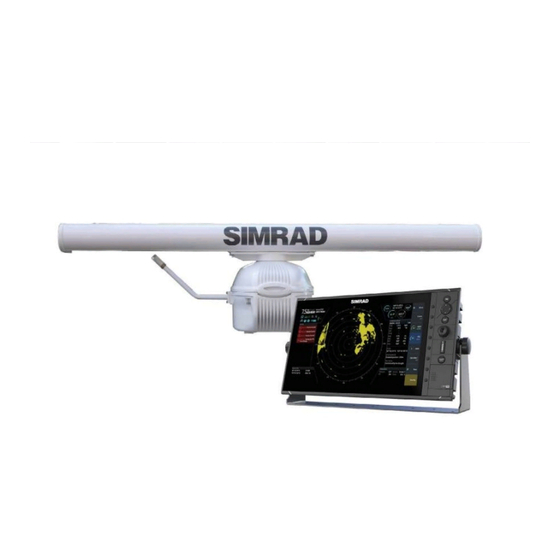
Related Manuals for Simrad R3016 12U/6X


Summary of Contents for Simrad R3016 12U/6X
- Page 1 R3016 12U/6X Installation Manual ENGLISH www.navico.com/commercial...
- Page 3 This equipment is intended for use in international waters as well as coastal sea areas administrated by member states pursuant to international conventions. The R3016 12U/6X Radar system complies with: • the Navigation requirements of Marine equipment directive (MED) 96/98/EC, and the last modification by directive 2015/559/EU, Annex A.1.
-
Page 4: About This Manual
About this manual This manual is a reference guide for installing the R3016 12U/6X radar system. The manual is written for the professional radar and marine electronics technicians, and assumes some prior knowledge and skills relevant to the type of work to be carried out. - Page 5 ® NMEA and NMEA 2000 are registered trademarks of the National Marine Electronics Association. ™ ™ and microSD are trademarks or registered trademarks of SD-3C, LLC in the United States, other countries or both. Preface | R3016 12U/6X Installation manual...
-
Page 6: Table Of Contents
31 Technical specifications 35 Spare parts 36 Accessories 37 Dimensional drawings Up-mast transceiver and antennas R3000 Power supply unit R3016 Control unit SI80 Signal Interface unit Antenna rotating diameter 39 Technical drawings System block diagram Contents | R3016 12U/6X Installation manual... -
Page 7: Introduction
To be able to provide consistent data, the R3016 12U/6X Radar system is designed to be integrated using serial interfaces with other electronic equipment normally present in a vessel bridge: •... -
Page 8: R3016 12U/6X Manuals
Connection to the R3016 Control unit is made via NMEA 2000. The SI80 provides power and termination for the backbone. R3016 12U/6X manuals The following documentation is delivered with the R3016 12U/6X Radar system: R3016 12U/6X Operator manual (988-10911-00n) User descriptions of the radar and of the features included in the system. -
Page 9: Connector Layouts
Connection for SI80 expands NMEA 0183 I/O Power 24 VDC power input and system failure alarm output NMEA 0183 (Serial 1) 2 x Inputs + 1 x Output NMEA 0183 (Serial 2) 2 x Inputs + 1 x Output Connector layouts | R3016 12U/6X Installation manual... -
Page 10: R3000 Power Supply Unit Connectors
Protects supply from output overcurrent Power LED Indicates state of the power supply input Status LED Indicates state of power input Ú Note: The drawing shows the power supply front cover removed for terminal access. Connector layouts | R3016 12U/6X Installation manual... -
Page 11: Installation Overview
12.5 12.5 12.5 12.5 2 m (6 ft) 3 m (9.8 ft) STBY STBY 12.5 12.5 2 m (6 ft) STBY R3016 12U/6X radar sensor Pulse compression radar Broadband radar Other pulse radar Installation overview | R3016 12U/6X Installation manual... -
Page 12: Obstructions And Blind Sectors
The following table indicates the effect of mounting height of antenna on the distance before the beam hits the water. Height Distance 14.1 18.8 23.5 35.3 47.0 Height (m) 15 Distance 70.6 94.1 117.6 141.1 188.2 235.2 Installation overview | R3016 12U/6X Installation manual... -
Page 13: Mounting Location
Drill bit set • 16 mm drill bit (needed for NMEA 2000 plugs) Ú Note: In case the heater system is included, additional tools are required. Refer to "Tools required" on page 18. Installation overview | R3016 12U/6X Installation manual... -
Page 14: Hardware Mounting
Fasteners should be of 316L stainless and property class 70 or better (bolt heads will be marked accordingly), or similar strength high tensile steel with a permanent protective coating system applied. Hardware mounting | R3016 12U/6X Installation manual... -
Page 15: Fitting The Control Unit
Mount the unit to the bracket using the knobs. Hand tighten only. The ratchet teeth in the bracket and display case ensure a positive grip and prevent the unit changing from the desired angle. Fix the bracket straps. Hardware mounting | R3016 12U/6X Installation manual... -
Page 16: Install The R3000 Power Supply Unit
The power supply must be installed on a vertical surface, with the cables exiting downwards. Where area of installation is poorly ventilated, provide space around all sides of the power supply, per the following diagram; Hardware mounting | R3016 12U/6X Installation manual... - Page 17 30mm (1.2”). The machine screws are 60mm (2.4”)”, so mounting surface should be no more than 40mm (1.6”) thick. Drill bit sizes for the self-tappers and machine screws are 2.5mm and 4.5mm respectively. Hardware mounting | R3016 12U/6X Installation manual...
-
Page 18: Adding The Heater System (Optional)
Install the heater R3000 power supply unit As the heater power supply housing is identical to the transceiver power supply unit, use the "Install the R3000 power supply unit" on page 16 for instructions. Hardware mounting | R3016 12U/6X Installation manual... - Page 19 Secure the temperature sensor with two supplied M3 pan head screws, and slide on the blue spade connectors. Insert the heater elements into the mounting holes and secure them in place using supplied M4 pan head screws. Hardware mounting | R3016 12U/6X Installation manual...
- Page 20 Follows a route of existing cables. Ensure the loom is secured to the existing loom at regular intervals using cable ties. Pass the loom through any cable clip that is used to support existing cables. Hardware mounting | R3016 12U/6X Installation manual...
-
Page 21: Install The Si80
Install the SI80 The SI80 is delivered with an Installation Guide (SI80_IG_988-10475-00n). See the guide for installation instructions. Hardware mounting | R3016 12U/6X Installation manual... -
Page 22: Wiring
Minimum bend radius of the Ethernet cable is 100 mm. Do not subject the cable to tighter bends, as distortion of the cable can degrade the cables performance, and at worst may break conductors due to fatigue. Wiring | R3016 12U/6X Installation manual... -
Page 23: Up-Mast Transceiver Grounding
Before inserting plugs, ensure the safety switch is set to the OFF position as marked on switch. All three connectors are keyed, so plug orientation cannot be done incorrectly. Ensure the retainer clip is fully engaged after insertion. Retention clip Wiring | R3016 12U/6X Installation manual... -
Page 24: Transceiver Power Supply Connection
It is recommended a minimum of 10mm2 (8 AWG) cable is used when doing short runs. The terminals will accept up to 25mm2 (4 AWG) cable. POWER STATUS PWR OUT PWR IN POWER STATUS PWR OUT PWR IN Wiring | R3016 12U/6X Installation manual... -
Page 25: Power Supply Diagnostics
LED, this is normal behavior. Control unit power and alarm output connection The R3016 Control unit power cable has four wires, two of which provide power to the unit, and two for the alarm output. Wiring | R3016 12U/6X Installation manual... -
Page 26: Connection Of Ethernet Cable To Control Unit
Sensor connection Any sensor connected to the R3016 12U/6X system should meet IMO performance standards and be certified. Failure to do so would make the rest of the system non-compliant. The R3016 control unit supports up to 4 inputs and 2 outputs for sensors. Expansion beyond the supplied 4 inputs and 2 outputs can be achieved by the addition of an SI80 through connection to the control unit’s NMEA 2000 port. -
Page 27: Serial Ports - Color Code
READER Configuration without BAM R3016 12U/6X must be connected to an External Position Fixing System (EPFS), a gyro- compass/heading sensor, and a SDME source via serial line. Ground stabilization requires an external sensor signal capable of providing an input and an indication of own ship’s speed over ground, for example from an EPFS, SDME or use of... - Page 28 Port 1 Port 3 Talker B (Tx+) Brown Port 1 Port 3 Talker A (Tx-) White Shield Drain Port 1 Port 3 Listener A (Rx-) Green Port 1 Port 3 Listener B (Rx+) Yellow Wiring | R3016 12U/6X Installation manual...
-
Page 29: Si80 Connection
An HDMI video output is provided for interface to a 3 party Voyage Data Recorder (VDR). The output mirrors the screen display, and is at the same resolution. The VDR connected to should accept digital video input, either using DVI or HDMI interface. Wiring | R3016 12U/6X Installation manual... - Page 30 NMEA2000 POWER NMEA0183 NMEA0183 Voyage Data Recorder with DVI input DVI connectors DVI – HDMI adaptor cable Ú Note: It is not possible for the user to deactivate video output to the VDR port. Wiring | R3016 12U/6X Installation manual...
-
Page 31: Technical Specifications
Relative wind velocity (According to IEC 62388) Power Transceiver up-mast unit Supply voltage (V DC) 50 Average power (W) 250. (Additional 300W if heater kit is included) R3016 Control unit Supply voltage (V DC) 24 Technical specifications | R3016 12U/6X Installation manual... - Page 32 IF amplifier Logarithmic IF dynamic (dB) IF center frequency (MHz) IF bandwidth (MHz) Short pulse 24 Medium pulse 4.8 Long pulse 1.8 Horizontal Beam width (deg.) 1.35 Vertical Beam width (deg.) VSWR < 1.20 Technical specifications | R3016 12U/6X Installation manual...
- Page 33 SI80 connection for IEC 61162-1 expansion Micro-C connector (to be used with Speed Log sensor, when BAM is present) HDMI output, same resolution as radar display Target tracking Acquisition Manual, up to 20 targets Technical specifications | R3016 12U/6X Installation manual...
- Page 34 Safe distance to the standard magnetic steering magnetic compass compass R3016 Control unit 0.65 m 0.43 m 12 kW X-Band SRT 1.43 m 0.87 m transceiver R3000 Power supply unit 0.3 m 0.24 m Technical specifications | R3016 12U/6X Installation manual...
-
Page 35: Spare Parts
Keypad PCB and buttons replacement 000-12408-001 SD door kit R3016 Card reader door and gasket replacement 000-12410-001 Dash mounting kit R3016 000-12412-001 Bracket mounting pack R3016 000-12414-001 Suncover R3016 000-12520-001 Bezel assembly edge R3016 Spare parts | R3016 12U/6X Installation manual... -
Page 36: Accessories
SI80 SIMRAD signal interface 000-0127-52 TR-120-KIT NMEA 2000 terminator kit 000-0119-88 Micro-C cable (0.6 m) NMEA 2000 cable 000-0127-53 Micro-C cable (1.8 m) NMEA 2000 cable 000-12386-001 Heater upgrade kit for SRT LAN Requires separate power cable Accessories | R3016 12U/6X Installation manual... -
Page 37: Dimensional Drawings
Dimensional drawings Up-mast transceiver and antennas 1800mm (70.8”) 458mm (18.0”) 364mm (14.3”) 524mm (20.6”) 146mm (5.7”) 178mm (7.0”) 200mm (7.9”) R3000 Power supply unit 213.0 mm (8.39") 195.0 mm (7.68") POWER STATUS Dimensional drawings | R3016 12U/6X Installation manual... -
Page 38: R3016 Control Unit
477 mm (18.77”) 120 mm (4.72”) SI80 Signal Interface unit 211 mm (8.29") 197 mm (7.77") 60 mm 185 mm (7.27") (2.36") 180 mm (7.08") 80 mm (3.15") 48 mm (1.88") Antenna rotating diameter Dimensional drawings | R3016 12U/6X Installation manual... -
Page 39: Technical Drawings
Technical drawings The System block diagram (992-21511-01A-R3016) is enclosed. System block diagram PREWIRED 2 x 000-12393-001 (2 m) Technical drawings | R3016 12U/6X Installation manual... - Page 40 www.navico.com/commercial...
Need help?
Do you have a question about the R3016 12U/6X and is the answer not in the manual?
Questions and answers