
Related Manuals for Simrad GB40


Summary of Contents for Simrad GB40
- Page 1 Manual Simrad GB40 Integrated Network System English Sw. 4 www.simrad-yachting.com A brand by Navico - Leader in Marine Electronics...
-
Page 2: Table Of Contents
1.6 Multiple panes in pages ........11 1.7 Controllers - OP30 remote/USB mouse ....12 1.8 Network the GB40 ..........13 1.9 Add an OP30 to a GB40........13 2 Setup 2.1 Setup: Units ............. 15 2.2 Setup: Chart ............ 17 2.3 Setup: Navigation .......... - Page 3 3 Chart 3.1 Chart Manager ..........31 3.2 Chart: The Basics ..........44 3.3 Chart: Display ..........45 3.4 Chart: Display features ........46 3.5 Chart: Show vessel status and position ....47 3.6 Chart: Position data sources ....... 47 3.7 Chart: Instant GoTo ..........
- Page 4 3.29 Chart: Overlays..........62 3.30 Chart: Overlay the radar ........63 3.31 Chart: Overlay ports & marinas ......64 3.32 Chart: Overlay tide information ......64 3.33 Chart: Overlay roads, terrain, bathymetry, SAR, GMDSS ............65 3.34 Chart: Information about an object ....66 3.35 Chart: Routes &...
- Page 5 4.2 3D Chart: Display..........82 4.3 3D Chart: Synchronize with Chart......82 4.4 3D Chart: View Adjustments ....... 83 4.5 3D Chart: Bathymetrics - Show/Hide....83 5 3D Steer 5.1 3D Steer: Display..........85 5.2 3D Steer: Reset the XTE ........85 6 AIS: Introduction 6.1 AIS: Screen............
- Page 6 7.18 Echosounder: Zoom range ......100 7.19 Echosounder: Zoom range shift ....... 101 7.20 Echosounder: Split zoom screen ...... 101 7.21 Echosounder: Split bottom lock ....... 102 7.22 Echosounder: Split ratio ......... 103 7.23 Echosounder: A-Scope - show/hide ....103 8 Radar 8.1 Radar: Introduction .........
- Page 7 9.3 Instruments: Configure gauge......132 9.4 Instruments: New panel ........133 10 Entertainment 10.1 Entertainment: File formats supported....136 10.2 Entertainment: USB drives......136 10.3 Entertainment: Video Juke Box......138 10.4 Entertainment: Music Jukebox ......139 10.5 Entertainment: DVD/CD ......... 143 11 Alarms 11.1 Alarms: Alarm Log.........
-
Page 8: Welcome To The Gb40
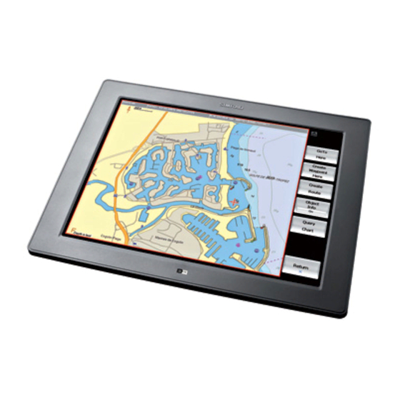
1 Welcome to the GB40 The GB40 (Glass Bridge 40) system is designed for easy use in the marine environment. The GB40 can integrate navigation, fishfinding, instrumentation, multimedia entertainment, and an onboard camera. Whatever type of boat you have and however you use it, you can customize the GB40 to meet your needs. -
Page 9: Warranty
So, if the cursor is positioned over the top edge, the chart scrolls from top to bottom. pane A " " is a part of a screen showing one GB40 function, such as the sounder, chart, radar, and so on. page A "... -
Page 10: Get Started
1.4 Get Started It's best to work through this section with the GB40 set up and running so you can try out the various functions and see the results. This section assumes you have one OP30 and the master unit in the system. - Page 11 Accept conditions of use Select • If there is no GPS signal going into the GB40 an alarm may • Acknowledge appear. If so, select A full-screen Chart pane is displayed. If you have a GPS signal • going into the system your position is centered on-screen.
-
Page 12: Multiple Panes In
A list of choices is displayed. Select the new setting. • 1.6 Multiple panes in pages The GB40 can save and recall combinations of panes, delivering several functions on screen at the same time. A collection of panes Page is called a... -
Page 13: Controllers - Op30 Remote/Usb Mouse
OP30. This will put the system back into the correct mode for mouse usage. Note: When a GB40 detects a mouse, an extra set of buttons above the main pane appears. These buttons are shortcuts to 12 | Welcome to the GB40... -
Page 14: Network The Gb40
GB40 system. If more than one display unit is used in the GB40 system, one of them must be specified as the master unit. The other display units are sometimes referred to as client units. - Page 15 • hold the PWR and MENU keys for 5-10 seconds. A double beep confirms that the unit has reset. Switch Off power on the GB40. Press and hold PWR for 5 • seconds on the OP30 to switch on. This new OP30 will register to each GB40 on the network, but will not operate any unit until it has been assigned control.
-
Page 16: Setup
2 Setup The setup options affect how the GB40 measures, displays and interacts with the environment around your vessel. Some setup options enable you to specify your preferences for information display formats but other setup options are important configurations that affect critical navigation settings. - Page 17 Units Default Description Distance Units Nautical Miles Sets the format for large distance units. Statute Miles Kilometers Distance Units Small Yards Sets the format for small distance units. Feet Meters Temperature Units Fahrenheit Sets the format for temperature units. Celsius Depth Units Feet Sets the format for depth units.
-
Page 18: Setup: Chart
2.2 Setup: Chart To enter setup options for Chart Pages Setup Select then from the main menu. • + Chart Select to display a list of options. • Return When you are finished, select • -Chart Default Description C-Map Chart Manager Activate Enters the C-Map Chart manager. -
Page 19: Setup: Navigation
2.3 Setup: Navigation To enter setup options for Navigation Pages Setup Select then from the main menu. • + Navigation Select to display a list of options. • Return When you are finished, select • -Navigation Default Description Bearing mode True Sets the mode in which all bearings are displayed on the screen. -
Page 20: Setup: Data Sources
-Navigation Default Description Waypoint Arrival Distance (0.01-1 Sets the distance between the vessel 0.03 Nautical and the active waypoint before the Mile) waypoint arrival alarm is activated and the next waypoint becomes active. At End of Route Stop Stop navigating. Cancels active route Navigating and stops sending information to the autopilot. -
Page 21: Setup: Tracks
To select the data source for a channel where more than one option is available: Pages Setup Select then from the main menu. • Select + Data Sources to display a list of options. • Return When you are finished, select •... -
Page 22: Setup: Radar
Radar Power on Action Standby When powered, the radar will warm up, then go into standby mode. Remain When GB40 is powered up, the radar will remain Off. Radar information Switch Displays magnetron hours information (for a 10 kW or 25 kW scanner only). - Page 23 These changes are global, meaning that they'll apply to all the Echosounder screens. You must enter an accurate value for the transducer depth. If you don't, all the depths on the Echosounder screens will be wrong. To enter setup options for Echosounder Pages Setup Select...
-
Page 24: Setup: Ais
2.8 Setup: AIS To enter setup options for AIS Pages Setup Select then from the main menu. • + AIS Select to display a list of options. • Return When you are finished, select • - AIS Default Description Activates AIS services. Dangerous Alarm activates when CPA is less than vessel alarm... -
Page 25: Setup: Entertainment
- AIS Default Description Show Vessel Hides the display of certain vessel by type categories. Filter by Hides the display of vessels outside the distance specified distance. (range units) Filter by Hides the display of vessels travelling speed (speed under a certain speed. units) Projected Displays a line indicating the course of... -
Page 26: Setup: Installation
When you are finished, select • - Installation Default Description Software Version Information Keypad Maps control devices to the GB40 Controller being set up. You may add and Status identify controllers on the network, as well as adjust sound and backlight levels. - Page 27 - Installation Default Description Network Diagnostics Displays diagnostic information regarding the network. Configure NMEA Output Displays a table showing NMEA sentences and status. Select the desired sentence and switch On/Off using the output button. Select Save when finished. Sentence Output APB (T) APB (M) NMEA Baud Rate...
-
Page 28: Setup: Vessel Statistics
- Installation Default Description Change Master Name Of Set which unit on the network is Processor going to perform as the system master. Select unit from list, press SELECT AS MASTER then OK to confirm. Change Location of Media Storage None Set None Select which processor on the... -
Page 29: Setup: Backup/Restore
When you are finished, select • - System Default Description Processor Name Re-name the processor if a more GB40 descriptive name is needed to help Processor identify it on the network. Use up to 15 name characters (letters and numbers only, with no spaces). - Page 30 - System Default Description Language English US Set the preferred language. English UK Decimal Separator Point Used to select separator between values e.g. Long/Latitude. Comma Select Time Zone Selected Set the local time zone. Allow for Time daylight saving if applicable. Select from Zone the list of time zones.
-
Page 31: Setup: Restore To Factory Defaults
Data Channel Diagnostics Channels snapshot dialog page. 2.14 Setup: Restore To Factory Defaults Navigation Data will be lost when GB40 is restored to Factory Defaults. You are recommended to perform a backup before taking this action. To enter setup options for Restore To Factory Defaults... -
Page 32: Chart
3 Chart The GB40 is supplied with default settings for all the Chart options, but you can change many of the settings to suit your own preferences. You can: set up your Chart Library • change your Chart settings •... - Page 33 All of the C-Map chart collections are pre-loaded into the GB40. You must purchase a license then unlock the code for each chart collection that you want to use, and then update this license annually.
- Page 34 Chart Manager: Display information The C-MAP PRO Chart Manager screen shows: the hardware key serial number • version number of the Chart Manager software • database number and issue • It also shows chart collection information including: the number of licenses in your license key (memory stick) •...
- Page 35 Chart Manager: Select a collection Chart collections icons indicate the status of the collection: Squares near the names of chart collections in the list of • available chart collections indicate price conditions: the chart collections with the squares of the same size have the same price.
- Page 36 ◦ Click on the region that you want charts for. The chart collections for that region appear on the map in blue and are listed below. ◦ Alternatively, select a chart collection from the list. It is displayed on the map in red. ◦...
- Page 37 C-Map chart license key. You must install the charts on the master unit. Any other display units can access the chart collections when the GB40 master unit is On. You can only install the collections that you have licenses for.
- Page 38 To install a selected collection: Select the collection from the list. • Install Selected. Select • A dialog box requesting your confirmation opens. Select either: • ◦ to install the selected collection OR ◦ if you do not want to install the collection. A progress bar appears indicating the installation status.
- Page 39 Return When you are finished, select • Chart Manager: Load a license This works only when the licence key with the license code file is connected to the GB40 master unit. To load the chart licenses: Pages Setup Select then from the main menu.
- Page 40 Chart Manager: Icons - no valid subscription 1 [Green] Collection is less than 2 months old. No valid subscription to the updating service. Required Action None. Chart Manager: Icons - no valid subscription 2 [Amber] Collection is between 2 and 4 months old. No valid subscription to the updating service.
- Page 41 Chart Manager: Icons - valid subscription 1 [Green] Collection is less than 2 months old. A valid subscription to the updating service exists. Required Action None. Chart Manager: Icons - valid subscription 2 [Amber] Collection is between 2 and 4 months old. A valid subscription to the updating service exists.
- Page 42 Chart Manager: Icons - collection in view Collection is in view. Required Action Double click to switch On/Off. Chart Manager: Icons - collection installed The collection is installed on the hard disk. Required Action None. Chart Manager: Icons - valid subscription 3 [Red] Collection has not been updated in 4 months.
- Page 43 Chart Manager: Icons - no icon No Icon The collection is not installed. Required Action None. Chart Manager: Icons - collection not installed The collection is not installed on the hard disk. Required Action Install collection. Chart Manager: Icons - cannot retrieve data Data cannot be retrieved from the hardware key (the hardware key may be unplugged).
- Page 44 Chart Manager: Icons - license does not exist [Fade] A license for this collection does not exist on the hardware key. Required Action Missing/expired license. Chart Manager: Icons - license expired [Red] A license for this collection exists on the hardware key and has expired.
-
Page 45: Chart: The Basics
Note: You must purchase and install the licenses for the chart collections that you want to access before you can display the charts on your GB40. This section also explains how you can: display your current position in real time •... -
Page 46: Chart: Display
Note: You can save yourself a lot of time by storing your preferred Chart settings for the Planning, Underway, Fishing, Anchored, and Local chart views. The electronic chart used by the Simrad GB40 is an aid to navigation designed to supplement, not replace, official government charts. Only official government charts supplemented by notices to mariners contain the information required for safe and prudent navigation. -
Page 47: Chart: Display Features
3.4 Chart: Display features The Chart always shows: an arrow with an N. This is the true North indicator. • an alphabetic letter to show the unit of depth (such as a large • M to indicate meters). a distance scale. •... -
Page 48: Chart: Show Vessel Status And Position
GPS satellites are the primary source of position data but, depending on the type of receivers that are connected to your GB40 and your personal preferences, you can choose to display your vessel's position as Lat/Long coordinates OR as Loran Time Differences (TDs) coordinates. -
Page 49: Chart: Goto/Show A New Coordinate
From Vessel • ◦ Select a point on your Chart. The GB40 shows the range and bearing on the Chart and in the main menu, with an estimate of the time it will take to travel that distance at your cruising speed (this is specified in your Vessel Statistics Setup). -
Page 50: Chart: Keep Your Vessel In View
The GB40 shows the range and bearing on the Chart and in the main menu, with an estimate of the time it will take to travel that distance at your cruising speed. -
Page 51: Chart: Pan The Chart
3.11 Chart: Pan the chart You can pan (move) the Chart to show areas that are outside the currently displayed area. To pan: Make the Chart pane active. • Identify the lightly shaded frame around the edge of the Chart (this may not be visible if there are any Chart overlays) Select the edge of the Chart once to move one step in that •... -
Page 52: Chart: Orientation - Head Up/North Up/Course Up
you make any changes to the Chart settings, those changes are saved when you exit that preset Chart view. Note: When you select a preset chart view for the first time, the default settings for that preset chart view are applied. 3.14 Chart: Orientation - Head Up/North Up/Course Up Whatever the Chart orientation, an indicator in the top left corner... -
Page 53: Chart: Vessel Offset Selection
Chart scrolls automatically to reposition your vessel and maintain a good view of what lies ahead. (You can change the distance to be traveled before the Chart scrolls automatically; see GB40 Setup: Navigation.) Center . -
Page 54: Chart: Customise The Chart Screen
Standard is the default. • Full shows the most detail. • If you change this setting, it's also changed on any other display units that show the same Chart view. To select the level of chart detail: Make the Chart pane active. •... -
Page 55: Chart: Vessel Symbol Selection
Note: You can store your preferred settings within the preset chart views for each of five common boating scenarios. 3.18 Chart: Vessel symbol selection You can show your vessel on the Chart screen as a vessel or as a compass rose. The vessel symbol is the default. To select the vessel symbol: Make the Chart pane active. -
Page 56: Chart: Chart Boundaries On/Off
If the chart guard zone is On, the chart guard zone is shown on all the charts displaying the same Chart view and the GB40 checks for hazards that are marked on the chart. If a hazard is identified, the guard zone alarm will operate if it's been turned on. -
Page 57: Chart: Safe Depths On/Off
If the chart guard zone is Off, it's not shown on the Chart and it isn't active. To turn the chart guard zone On or Off: Guard Zone Select . (If this button is not in the main menu, • Return / Settings make the Chart pane active, or select Guard Zone... -
Page 58: Chart: Light Sectors On/Off
3.25 Chart: Light sectors on/off You can switch the light sectors On or Off on your Chart. Some lights show different colors when they're viewed from different bearings. The different colors indicate different light sectors. Although the color of the light will change depending on your bearing, the characteristics of the light, such as a three second flash, will not change. -
Page 59: Chart: Text On/Off
3.27 Chart: Text on/off You can toggle the names of islands, oceans, towns, and places of interest On or Off on your Chart. Chart Detail must be set to Full if you want to show the chart text (see Chart: Detail selection). To change the chart text setting: Chart Presentation Select... - Page 60 Chart: Default values for preset chart views The five preset Chart views (Planning, Underway, Fishing, Anchored, and Local) have the following default settings: Planning Chart scale 1:150,000 Chart center 1:150,000 Show boat Show boat mode Center Chart orientation North Up Guard zone Predictor Track...
- Page 61 Underway Predictor Track Boat symbol Boat Chart detail Standard Tides Info Shade safe depths Hide safe soundings Light sectors Chart text Chart boundary Lat/Long grid Ports and Marinas overlay Chart object overlay Radar overlay Fishing Chart scale 1:20,000 Chart center 1:20,000 Show boat Show boat mode...
- Page 62 Fishing Chart boundary Lat/Long grid Ports and Marinas overlay Chart object overlay Radar overlay Anchored Chart scale 1:20,000 Chart center 1:20,000 Show boat Show boat mode Center Chart orientation North Up Guard zone Predictor Track Boat symbol Boat Chart detail Full Tides Info Shade safe depths...
-
Page 63: Chart: Overlays
Local Show boat Show boat mode Center Chart orientation Head Up Guard zone Predictor Track Boat symbol Boat Chart detail Full Tides Info Shade safe depths Hide safe soundings Light sectors Chart text Chart boundary Lat/Long grid Ports and Marinas overlay Chart object overlay Radar overlay 3.29 Chart: Overlays... -
Page 64: Chart: Overlay The Radar
a shaded relief map that shows topographic information for • land bathymetric information for the ocean. • 3.30 Chart: Overlay the radar You can overlay the Radar returns on the Chart. This is extremely useful because it can help you to easily interpret the radar image by correlating the radar targets with charted objects. -
Page 65: Chart: Overlay Ports & Marinas
• displayed. Query Chart. Select The GB40 displays the Chart Object • Details box which shows more information about the marina. There may be a scroll bar at the side of the right hand box. Drag the scroll bar to see any other information. -
Page 66: Chart: Overlay Roads, Terrain, Bathymetry, Sar, Gmdss
To show or hide the tidal flow and currents: Chart Overlays Select . (If this button is not in the main • Return / menu, make the Chart pane active, or select Settings Tidal Flow & Currents button displays the current •... -
Page 67: Chart: Information About An Object
Chart pane active, or select Settings More Overlays Select • The GB40 displays the More Overlays box with a list of overlays and their current status. ( means the overlay is On, means the overlay is Off.) Select an overlay. Overlay Enabled... -
Page 68: Chart: Create/Name A New Route
Edit If you want to make changes to the new route, select • Route. Finish Select to confirm the route is complete. • The GB40 immediately shows a summary of the new route in a Route Details box. Chart |67... -
Page 69: Chart: Copy A Route
Select the route to delete. You cannot delete an active route. • Delete Route Select . The GB40 asks for confirmation. Select • To show or hide a route using the Routes Library: Select the route that you want to show or hide. -
Page 70: Chart: Select & Follow/Stop A Route
The GB40 automatically selects the first waypoint as the destination waypoint. When your vessel arrives at the specified distance from the waypoint, the GB40 automatically sets the next waypoint as the new destination waypoint and shows the completed leg as a grey line. -
Page 71: Chart: Manage With Chart
To stop following an active route: You can either: • ◦ GoTo Cancel Follow Route select then ◦ Cancel Follow select one of the route legs then select Route 3.40 Chart: Manage with chart Adding, deleting, moving or editing route waypoints is usually done directly on the Chart. -
Page 72: Chart: Manage With Routes Library
Finish When you've amended your route waypoints, select • Any changes are stored in the Routes Library. To add an existing waypoint to a route: Select the route. • Route Details Select • Select the waypoint that is positioned before the waypoint that •... - Page 73 Select the waypoint you want to move and drag it to the new position. Share Waypoints is On, the GB40 checks whether there's • more than one waypoint at that position. If a waypoint is being shared with another route, the waypoint is moved if the other route is visible.
-
Page 74: Chart: Goto Next Or Previous Waypoint
• Previous Waypoint Next Waypoint select The GB40 creates a temporary waypoint at your vessel's current position, then draws a line between the temporary waypoint and the destination waypoint. 3.43 Chart: Reverse a route Note: This works only when a route is displayed on the Chart. -
Page 75: Chart: Tracks
If you choose to show your current track, it appears as a purple line on the chart with a broken line connecting the last track point to the vessel symbol. The GB40 stores your track automatically in the Tracks Library. -
Page 76: Chart: Track - Show/Hide
Track points are not shown when the Radar is On but the track line is visible. The GB40 always stores your track automatically in the Tracks Library. You can switch your track On or Off. If it's On, your track is shown as a purple line. -
Page 77: Chart: Manage The Track Library
To delete a track from the Track Library: Select the track to delete. • Delete Track Select . The GB40 asks for confirmation. • Select • To rename a track: Select the track you want to rename. -
Page 78: Chart: Waypoints
• Plot Waypoint Here • Select The GB40 immediately creates the new waypoint. The Waypoint Details box is displayed with some details (such as the latitude and longitude of the waypoint) already entered. Edit the waypoint information if you wish. -
Page 79: Chart: Navigate & Manage Your Waypoints
To change the waypoint details Either create a new waypoint or select an existing • Waypoint Details waypoint/event mark then select EDIT Select next to the setting you want to change. Most • fields use alphanumeric entry. To change the waypoint icon: Select the icon. -
Page 80: Chart: Manage The Waypoints Library
Select the waypoint OR select . (If this button is not in • Return the main menu, make the Chart pane active, or select / Settings Cancel GoTo Waypoint Select . The GB40 immediately • deactivates the active route. Chart |79... - Page 81 Blank page 80 | Chart...
-
Page 82: Chart
4 3D Chart 3D Chart information is supplied by C-Map. You can use 3D Chart to see a panoramic view of the selected area, as if you were flying over it. You can change your elevation and the angle of view, and zoom in and out to show more or less detail. -
Page 83: Chart: Display
• in one of the panes.) If position data is available, the GB40 acquires your vessel's position then displays the local area as a 3D Chart with your vessel shown on it and the 3D Chart main menu on the right side of your screen. -
Page 84: Chart: View Adjustments
4.4 3D Chart: View Adjustments You can orient the current view of 3D Chart to show the view from different perspectives. Note: The best controller to use with 3D chart is a USB mouse, as it allows live dragging to position the camera view. The cursor keys on the OP30 may also be used. - Page 85 To change the bathymetric setting: Display the 3D Chart screen and the main menu. If you can't • Bathymetric Settings. see the button, select Bathymetric button shows the current setting. Select it • to change the setting. 84 | 3D Chart...
-
Page 86: Steer
Pages. Select • 3D Steer Select . The GB40 displays a graphical • representation of the view from your vessel to the next waypoint. If your vessel is: ◦ on track, 3D Steer shows a XTE reading of zero. The roadway is in the middle of the screen, with your vessel on the centerline. - Page 87 Reset XTE Display 3D Steer then select • The GB40 immediately creates a temporary waypoint at your current position and draws a new leg between this and the next waypoint. It also resets the bearing and distance readouts. 86 | 3D Steer...
-
Page 88: Ais: Introduction
Note: AIS notification on your system is automatic and requires no operational instructions. However, you can customize the settings for the AIS display on your GB40. If you change the filter options in the AIS Setup Menu, the changes may hide some vessels on your display without your knowledge. -
Page 89: Ais: Screen
6.1 AIS: Screen Please refer to the Setup section for information on AIS Setup. 88 | AIS: Introduction... -
Page 90: Echosounder
7 Echosounder The Echosounder is a high quality, dual frequency fishfinder. An ultrasonic pulse from your hull-mounted transducer travels down towards the bottom and spreads outwards into a rough cone shape. Depth to a target or the bottom is found by measuring the time taken between sending the pulse and receiving the echo. -
Page 91: Echosounder: Screen
7.2 Echosounder: Screen The Echosounder pane shows each echo as a vertical line of pixels. The echoes can be returned from 50 kHz only, from 200 kHz only, or from both of these frequencies mixed together. The band of color scrolling from right to left shows the bottom, and any fish (or other objects) in the water are shown as fish arches. -
Page 92: Echosounder: Interpret The Screen
sonar frequency • type of view • depth at the current cursor position. • 7.3 Echosounder: Interpret the screen With practice and experience it's possible to interpret the echoes on the Echosounder panes quite accurately. You can learn to recognize different fish, the type of bottom and shadows. The water depth, the scroll speed and the echo strength can affect the quality of the display. - Page 93 of water, rather than just displaying everything from the surface to the bottom. Zooming in increases the amount of screen space the sonar data can be represented in, and is necessary for good fish arches. It is difficult to get fish arches in shallow water as the •...
-
Page 94: Echosounder: Operating Modes
Echo strength variability The colors on the Echosounder pane indicate differences in the strength of the echoes. However, when you're trying to interpret the strength of an echo, remember that it can be affected by many factors such as: the size of the object (bigger objects return more echoes). •... -
Page 95: Echosounder: Colors
• Echosounder pane shows a longer history with less fish detail, or a shorter history with more fish detail. Note: If another GB40 display unit is operating the Echosounder at a different frequency to you, the scroll speed will slow. -
Page 96: Echosounder: Pulse Power
To change the scroll speed: Display the Echosounder pane and the main menu. If you can't • Settings Return see the button, select Settings. Select • Scroll Speed button shows the current setting. Select it • to change the setting. ◦... -
Page 97: Echosounder: Threshold Setting
You can adjust the gain settings for the 50 kHz and 200 kHz frequencies independently of each other. To change the gain setting: Display the Echosounder pane and the main menu. If you can't • Gain and Filters Return see the button, select Gain and Filters Select... -
Page 98: Echosounder: Noise Filter
7.10 Echosounder: Noise filter This filters the echo signal and reduces high-level, spiky interference, such as engine noise. However, some detail may be lost and small fish may not be shown if you are using the highest setting. To change the noise filter setting: Display the Echosounder pane and the main menu. -
Page 99: Echosounder: Depth Value
To change the depth line setting: Display the Echosounder pane and the main menu. If you can't • Display Options Return see the button, select Depth Line button shows the current setting. Select it to • change the setting. Note: If you can't see the depth line, check whether it's On. If it is On but you can't see it, try changing the range because it may be out of view. -
Page 100: Echosounder: Auto Range
To show the 50/200 kHz split pane: Display the Echosounder pane and the main menu. If you can't • Range, Zoom and Split Return see the button, select Range, Zoom and Split View Mode Select . The button • shows the current setting. 50/200 Select . -
Page 101: Echosounder: Range
7.16 Echosounder: Range Range is the vertical extent shown on the Echosounder screen. You can increase or decrease the range. To change the range: Display the Echosounder pane and the main menu. If you can't • Range, Zoom and Split Return see the button, select... -
Page 102: Echosounder: Zoom Range Shift
To change the zoom range: Display the Echosounder pane and the main menu. If you can't • Range, Zoom and Split Return see the button, select Range, Zoom and Split Select • Zoom Range button, and the echosounder zoom pane, •... -
Page 103: Echosounder: Split Bottom Lock
It's useful to have the depth line On. To select a split zoom pane: Display the Echosounder pane and the main menu. If you can't • Range, Zoom and Split Return see the button, select Range, Zoom and Split View Mode Select . -
Page 104: Echosounder: Split Ratio
You can use the split ratio to adjust the sizes of a split pane. This option is available only on the split zoom, the split bottom lock, and the split 50/200 pane. The GB40 must be displaying one of these Echosounder pane. - Page 105 To show or hide the A-Scope: Display the Echosounder pane and the main menu. • Display Options Select • A-Scope button shows the current setting. Select it to • change the setting. ◦ Off. The A-Scope is hidden. ◦ Standard. The standard A-Scope is shown in the right side of your Echosounder pane.
-
Page 106: Radar
ALL the Radar screens in your network. Note: Before using the radar for the first time, some details must be set up so that the GB40 can configure it correctly. These details should have been set up by your GB40 installation technician, but you are able to configure them in the Radar Setup options. -
Page 107: Radar: Screen
8.3 Radar: Screen The default Radar screen shows the following items, but you can show, hide or change many of these to suit your own preferences: a status bar along the top. • range rings. Range rings estimate the distance of a target from •... -
Page 108: Radar: Status Bar
8.4 Radar: Status bar The status bar is shown at the top of all the Radar screens. Use it to quickly check the: Radar range • the spacing value between the range rings • Radar orientation (Head Up, North Up, Course Up) •... -
Page 109: Radar: Range Offset (Trigger Delay)
Radar screen. (If you're in Course Up orientation but don't have an active route, the GB40 uses Head Up orientation until a route is made active) Note: North Up and Course Up require heading data or COG to operate. -
Page 110: Radar: Ppi Position - Look Ahead/Center/Offset
To change the radar range offset: Display the Radar screen and main menu. If you can't see the • Adjust Radar Return button, select Adjust Radar Installation Select then • Radar Range Offset Down Select then use • adjust the current setting. Select •... -
Page 111: Radar: True Or Relative Motion Mode (Tm/Rm)
Set Offset If you select , a message asks you to select the • new position for the PPI center. Enter the new position. The PPI center immediately moves to • the new location. If you want to return the PPI center to Look Ahead, just select •... -
Page 112: Radar: Gain, Rain Clutter, Sea Clutter Adjustment
◦ Range Rider . Select this to adjust the radar gain yourself for a particular radar range, and to have the GB40 store those settings and re-use them whenever you operate at that radar range. ◦... - Page 113 Radar: Gain adjustment You can use the radar gain to adjust the sensitivity of the radar. The radar gain should be set so that background noise is just visible on the Radar screen. The radar gain is shown as a percentage.
- Page 114 Radar: Rain clutter adjustment Rain clutter is visual noise on the Radar screen created by interference from rain, hail or snow. The rain clutter adjustment is a combination of the FTC (Fast Time Constant) that defines the leading edge of a rain shower but suppresses echoes from the following body of rain, so that any targets in the rain shower area are shown more clearly;...
-
Page 115: Radar: Preferences
◦ . Operate interference rejection at minimum strength. This is the default. ◦ Medium Operate interference rejection at medium strength. ◦ High . Operate interference rejection at maximum strength. This setting can make it more difficult to detect some targets and radar beacons. Use this setting only when necessary. - Page 116 If the bearing mode is set to true, the North indicator always points to true North. You can switch the North indicator On or Off. On the default. To change the north indicator line setting: Display the Radar screen and main menu. If you can't see the •...
-
Page 117: Radar: Range & Bearing
Radar: Active waypoints & routes - show/hide You can show or hide the active waypoint or active route on your Radar screen. You can show the name, the range and bearing, and the TTG for the active waypoint. If an active route or waypoint is shown on your Radar screen, you can switch the details On or Off. - Page 118 readout to show the Lat/Long position (if GPS data is available). Return When you are finished, select • Note: If there's no heading data available from a heading sensor, the bearing readouts are relative to your vessel's head. Radar: Fixed VRM/EBL You can show or hide the VRM/EBL (Variable Range Marker/Electronic Bearing Line) independently on your Radar screen.
- Page 119 Adjust VRM 1 Down select then use to increase or decrease the radius of VRM1 until it touches the target. The GB40 updates the range readout with each change in • radius. Select when you are at the target. •...
- Page 120 The GB40 updates the bearing readout with each change. • Select when you are at the target. Return When you are finished, select • If you want to find the range and bearing of another target • VRM/EBL 2 from your vessel, select then repeat the sequence.
- Page 121 Down select then use to increase or decrease the radius of VRM1 until it touches the target. The GB40 updates the range readout with each change in radius. Select when you're at the target. • To show the bearing readout: You can either: •...
-
Page 122: Radar: Targets
8.14 Radar: Targets This section explains how to: make small targets more easy to see • switch target trails On or Off, change the length of the target • trails, and temporarily clear target trails from the Radar screen Radar: Target enlargement You can turn the Expand Target feature On or Off. -
Page 123: Radar: Marpa
To clear target trails: Display the Radar screen and main menu. If you can't see the • Presentation Return button, select Presentation Select • Clear Trails Select . The target trails immediately disappear. • However, the target trails will start to appear again unless you switch them Off. - Page 124 Radar: Show details of one target You can show the details of a tracked target on the Radar screen. The GB40 can show the details of only ONE target at a time. Radar |123...
- Page 125 • MARPA Data Select . A message asks you to select the • target. Select the target. The GB40 displays a data box beside that target, showing: ◦ range and bearing ◦ speed and course ◦ closest point of approach ◦...
- Page 126 To remove a lost target: Acknowledge Select • The GB40 removes the target from the Radar screen and deletes all the stored data for that target. Radar: Vector settings Each of the tracked targets has a vector that indicates the target's speed and course.
-
Page 127: Radar: Guard Zones
Radar: Target history The GB40 stores the history of all the tracked targets for a period of time (specified by the vector length setting) and can show this history as a graphical representation. You can switch the history On or Off. Off is the default. - Page 128 Radar: Guard zone settings There are two radar guard zones, Guard Zone 1 and Guard Zone 2. You can customize each one, independently of the other, to suit your own preferences. The changes are applied to all the Radar screens. You can change the size, shape, and location of each radar guard zone.
- Page 129 Radar: Sensitivity of guard zone alarms You can set the sensitivity of the radar guard zone alarm to define the size of the target that will trigger the alarm. 100% is maximum sensitivity, meaning that very small targets will trigger the guard zone alarm. 0% is minimum sensitivity, meaning that only very large targets will trigger the alarm.
- Page 130 Check that the Chart has the Radar Overlay turned On. • Select the Radar pane so that it becomes active. If you can't • Adjust Radar Return see the button, select Adjust Radar Installation Select , then select • Bearing Alignment button shows the current setting.
- Page 131 Blank page 130 | Radar...
-
Page 132: Instruments
9 Instruments The instruments panel is displayed most clearly as a single pane but you can also show it in a half-pane or quarter pane. You can customize several features to suit your preferences. 9.1 Instruments: Screen 9.2 Instruments: Display You can select any panel, then display or customize it. -
Page 133: Instruments: Configure Gauge
◦ Rename Panel . Rename the current panel. Use the keyboard to enter a new name for the panel. Select ◦ Delete Panel . Delete the current panel. Confirm the deletion. Select 9.3 Instruments: Configure gauge You can show data on a gauge in digital or analog format. Digital is the default. -
Page 134: Instruments: New Panel
Note: Only valid numerical entries will be accepted for gauge configuration. Return When you have configured your gauge, select until • Save Changes Save you see the button, then select Changes This completes the analog gauge configuration. 9.4 Instruments: New panel To create a new panel Pages Instruments. - Page 135 Note: If the data channel selected is not receiving data, digital gauges will display blank lines and analog gauges will not have an indicator needle showing. 134 | Instruments...
-
Page 136: Entertainment
GB40 pauses the playback and resumes it only when you display that pane again. If you're playing music in a pane, the GB40 will continue to play the music, even if the pane is not active or visible, until you pause the music or select another pane that has audio. -
Page 137: Entertainment: File Formats Supported
The Music Jukebox and the Video Jukebox will list any media files on a USB drive that's connected to the GB40. When the USB drive is removed from the GB40, the media files on the USB drive are no longer listed in the Music Jukebox and the Video Jukebox. - Page 138 Entertainment: USB drive - play media To play media files from a USB Drive: Insert the USB drive into the USB slot on the GB40. • Display Music JB Video JB Select then • Playlist Library Video Library Select , as appropriate.
-
Page 139: Entertainment: Video Juke Box
Select the video that you want to play. • Play Selected Video Select • The GB40 shows a track progression box at the bottom of the screen. You can use the following buttons to control the video display: • ◦... -
Page 140: Entertainment: Music Jukebox
10.4 Entertainment: Music Jukebox The music jukebox allows you to: select and play music from the Music Library. • create, edit, play and delete playlists. • view the contents of the Music Library by album, artist, genre • or playlist. queue more music. - Page 141 To create a playlist: Playlist/Library Select • Create/Edit Playlist. Select • EDIT Select then use the onscreen keyboard to enter the new • playlist name. To add tracks to a playlist: Add to Highlight tracks in your Music Library then select •...
- Page 142 Select the item (or items) that you want to play. Selected • items have a black background. Play Selected Music Select to start playing. • The GB40 shows a progress bar at the bottom of the screen. Entertainment |141...
- Page 143 • return to the previous track. Note: If you're playing music in a pane, the GB40 will continue to play the music - even if the pane is not active or not visible - until you pause the music or select another pane that has audio.
-
Page 144: Entertainment: Dvd/Cd
Note: If you are playing music in a pane, the GB40 will continue to play the music - even if the pane is not active or not visible - until you pause the music or select another pane that has audio. - Page 145 To play a DVD: Pages DVD/CD Select then • Insert the DVD into the drive. • Play Select • Note: If you leave the DVD pane without pausing or stopping play, the GB40 will automatically pause the DVD. 144 | Entertainment...
-
Page 146: Alarms
11 Alarms The GB40 has various alarms that you can switch On/Off and customize to suit your vessel. These alarms can automatically: notify you of the vessel's status (for example, when you're • approaching a waypoint) alert you to potentially dangerous situations (for example, •... -
Page 147: Alarms: Customize
Use this button to activate or turn Off the selected alarm. You can set the audio to sound once, continuously, or not at all for some alarms. Audible alarms will interrupt any other audio playing through the GB40. ◦ Audible button displays the current setting. -
Page 148: Alarms: Acknowledgement
If another alarm is triggered when an alarm is already show in the Alarm Notification box, the GB40 checks the priority level of the new alarm. The alarm with the highest priority is displayed over any lower priority alarms. - Page 149 • Take any corrective action required. • Note: The GB40 resets some alarms, such as the Waypoint Arrival alarm and the Waypoint Arrived End of Route alarm, automatically after a set time period. The GB40 resets other alarms automatically when the sensor data is within the trigger settings again.
-
Page 150: Index
Screen ............81 Synchronize with Chart........82 View Adjustments......... 83 3D Steer............85 Display ............85 Reset the XTE ..........85 Add an OP30 to a GB40 ........13 Introduction..........87 Screen ............88 Alarms ............145 Acknowledgement ........147 Alarm Log...........145 Customize ..........146... - Page 151 Lat/Long grid overlay on/off......57 Light sectors on/off ........57 Manage the Track Library ....... 76 Manage the Waypoints Library ......79 Manage with chart......... 70 Manage with Routes Library ......71 Navigate & manage your waypoints ....78 Orientation - Head Up/North Up/Course Up ..51 Overlay ports &...
- Page 152 Icons - license expired ........43 Icons - no icon ..........42 Icons - no valid subscription 1 ......39 Icons - no valid subscription 2 ......39 Icons - no valid subscription 3 ......39 Icons - valid license ........44 Icons - valid subscription 1 ......
- Page 153 MARPA ............122 Master Set Master ........... 12 Media Formats Supported ........ 136 Multiple panes in pages ........11 Music Jukebox..........139 Network the GB40 ..........13 OP30 Add an OP30 controller ........13 OP30 Controller..........12 152 | Index...
- Page 154 Radar ............105 Acquire a target ..........123 Active waypoints & routes - show/hide....116 Cancel a target..........123 Colors ............114 Display ............105 Fixed VRM/EBL ..........117 Floating VRM/EBL ........119 Gain adjustment..........112 Gain mode - Manual/Range Ride/Auto ....111 Gain, Rain clutter, Sea clutter adjustment ..111 Guard zone settings ........127 Guard zones ..........126 Guard zones - on/off ........126...
- Page 155 Restore To Factory Defaults ......30 System............28 Tracks ............20 Units ............15 Vessel Statistics ..........27 Start Up ............9 Terms and conventions........8 USB Media Storage ......... 137 Video Jukebox..........138 Warranty............8 Welcome to the GB40..........7 154 | Index...
Need help?
Do you have a question about the GB40 and is the answer not in the manual?
Questions and answers