Simrad GO XSE Operator's Manual
Hide thumbs
Also See for GO XSE:
- Operator's manual (204 pages) ,
- Installation manual (84 pages) ,
- Getting started (41 pages)
Table of Contents
Advertisement
Quick Links
Advertisement
Table of Contents

Subscribe to Our Youtube Channel
Related Manuals for Simrad GO XSE


Summary of Contents for Simrad GO XSE
- Page 1 GO XSE Operator Manual ENGLISH simrad-yachting.com...
- Page 3 Fishing Hot Spots Inc. Copyright© 2012 Fishing Hot Spots. ™ ™ FUSION-Link Marine Entertainment Standard is a registered trademark of FUSION Electronics Ltd. C-MAP is a trademark of Jeppesen. Preface | GO XSE Operator Manual...
-
Page 4: Regulatory Statements
This equipment is intended for use in international waters as well as coastal sea areas administered by the USA, and countries of the E.U. and E.E.A. This equipment complies with: • CE under 2014/53/EU Directive Preface | GO XSE Operator Manual... -
Page 5: About This Manual
Manual version This manual is written for software version 1.0. The manual is continually updated to match new software releases. The latest available manual version can be downloaded from simrad- yachting.com. Preface | GO XSE Operator Manual... - Page 6 Drag finger on the screen in any direction. • Zoom In/Out Select the relevant panel button. Touch operation: Use pinch or spread gestures. • Exit the PDF viewer Select the X in the upper right corner of the panel. Preface | GO XSE Operator Manual...
- Page 7 The software version currently on this unit can be found in the About dialog. The About dialog is available in the System Settings. For information regarding upgrading your software, refer to "Software upgrades" on page 149. Preface | GO XSE Operator Manual...
- Page 8 Preface | GO XSE Operator Manual...
-
Page 9: Table Of Contents
Chart scale Panning the chart Positioning the vessel on the chart panel Displaying information about chart items Using the cursor on the chart panel Creating routes Find objects on chart panels 3D charts Chart overlay Contents | GO XSE Operator Manual... - Page 10 Activating the autopilot Switching from automatic mode to manual steering Autopilot indication on the pages The Autopilot panel Mode overview Standby mode Non-Follow Up (NFU, Power steering) Follow-up steering (FU) AUTO mode (auto compass) NoDrift mode Contents | GO XSE Operator Manual...
- Page 11 NAV mode WIND mode WIND Nav mode Turn pattern steering Using the GO XSE in an AP24/AP28 system Using the autopilot in an EVC system Autopilot settings Echosounder The Echosounder image Zooming the image Using the cursor on the image...
- Page 12 136 The Audio panel 138 Setting up the audio system 139 Operating the audio system 139 Favorite channels 139 Sirius radio (North America only) 140 Time plots 140 The Time plot panel 140 Selecting data Contents | GO XSE Operator Manual...
- Page 13 149 Maintenance 149 Preventive maintenance 149 Cleaning the display unit 149 Cleaning the media port door 149 Checking the connectors 149 Software upgrades 150 Service assistant 150 Backing up your system data 153 Touchscreen operation Contents | GO XSE Operator Manual...
- Page 14 Contents | GO XSE Operator Manual...
-
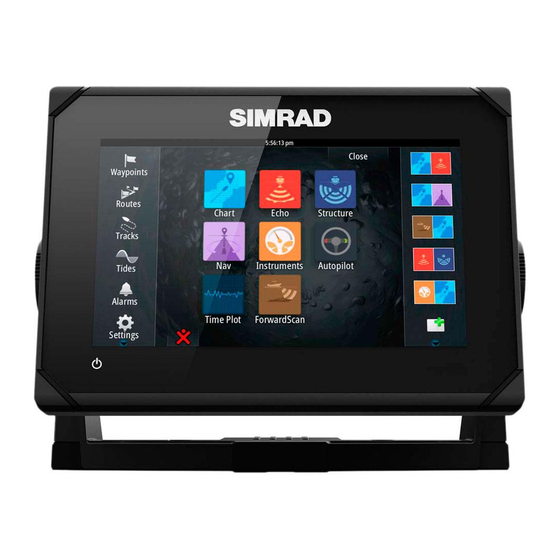
Page 15: Introduction
Select to exit the Home page and return to the previous active page. Favorites Select a button to display the panel combination. Press and hold a favorite button to enter edit mode for the Favorites panel. Introduction | GO XSE Operator Manual... -
Page 16: Application Pages
Display the dialog by a short press on the Power key or by swiping down from top of the screen. Status bar Dialog Information to or input from the user. Alarm message Displayed if dangerous situations or system faults occur. Introduction | GO XSE Operator Manual... - Page 17 All preconfigured favorite pages can be modified and deleted, and you can create your own. You can have a total of 12 favorite pages. For more information, refer to "Adding new favorite pages" on page 26. Introduction | GO XSE Operator Manual...
-
Page 18: Integration Of 3 Rd Party Devices
SmartCraft VesselView integration SmartCraft data can be displayed and interaction are enabled through the GO XSE when a VesselView 7 or VesselView 4 gateway device is present on the network. The engine supplier icon appears on the Home page when a device is available. -
Page 19: Remote Controllers
You can connect a remote controller to the network and remotely control the unit. To find out which remote controllers can be used, refer to the product web page at: simrad-yachting.com. A separate manual is included with the remote controller. Introduction | GO XSE Operator Manual... -
Page 20: Basic Operation
You turn the system on and off by pressing and holding the Power key. You can also turn the unit off from the System Controls dialog. If the Power key is released before the shut-down is completed, the power off process is cancelled. Basic operation | GO XSE Operator Manual... -
Page 21: Display Illumination
Using menus and dialogs Menus You display a page menu by selecting the MENU button in the upper right corner of the page. • Activate a menu item and toggle on/off an option by selecting it Basic operation | GO XSE Operator Manual... -
Page 22: Selecting Pages And Panels
Creating a Man Overboard waypoint If an emergency situation should occur, you can create a Man Overboard (MOB) waypoint at the vessel’s current position by selecting the MOB button on the Home page. Basic operation | GO XSE Operator Manual... -
Page 23: Screen Capture
When the function is activated, you can take a screenshot on a touch screen by double-selecting the title bar of an open dialog, or by double-selecting the status bar if no dialog is open. To view files, refer to "Files" on page 145. Basic operation | GO XSE Operator Manual... -
Page 24: Customizing Your System
Select the adjust splits option in the dialog Adjust the panel size by dragging the adjustment icon Confirm your changes by tapping one of the panels or selecting the save option in the menu. Customizing your system | GO XSE Operator Manual... -
Page 25: Password Protection
Files, activated from the Tools panel • GoFree Shop, activated from the Tools panel • Settings, activated from the Chart menu under Chart Options You set and remove password protection from the system Settings dialog. Customizing your system | GO XSE Operator Manual... -
Page 26: Adding New Favorite Pages
- Select the tool icon on a favorite icon to display the page editor dialog Add or remove panels in the page editor dialog Save or discard your changes to leave the favorite edit mode. Customizing your system | GO XSE Operator Manual... -
Page 27: Setting The Appearance Of The Instrument Bar
Select Edit to change an instrument gauge followed by the gauge you want to change Select the content you want to display from the Choose Data dialog Select Menu and then Finish editing to save your changes. Customizing your system | GO XSE Operator Manual... - Page 28 The more efficient you consume fuel, the more the outer blue dial creeps up towards the green portion of the scale. If you achieve the nominal efficiency of your vessel you will be at the green zone. If Customizing your system | GO XSE Operator Manual...
- Page 29 Economy button on the Fuel settings dialog. When you reset it, the system starts calculating the new average. Set the measurement units for the fuel economy gauge in the Economy field in the Units settings dialog. Customizing your system | GO XSE Operator Manual...
-
Page 30: Charts
Range rings* Track* Chart range scale Range rings interval (only displayed when Range rings are turned on) * Optional chart items. You turn the optional chart items on/off individually from the Chart settings dialog. Charts | GO XSE Operator Manual... -
Page 31: Chart Data
You can select a dual chart panel by pressing and holding the Chart application button on the Home page, or by creating a favorite page with two chart panels. Charts | GO XSE Operator Manual... -
Page 32: Vessel Symbol
Positioning the vessel on the chart panel Chart orientation Several options are available for how the chart is rotated in the panel. The chart orientation symbol in the panel’s upper right corner indicates the north direction. Charts | GO XSE Operator Manual... -
Page 33: Displaying Information About Chart Items
(photos) associated with the location or object. Note: Ú Pop-up information has to be enabled in chart settings to see basic item information. Charts | GO XSE Operator Manual... -
Page 34: Using The Cursor On The Chart Panel
Without removing your finger from the screen, drag the selection circle over the desired item to display item information. When you remove your finger from the screen the cursor reverts to normal cursor operation. Charts | GO XSE Operator Manual... -
Page 35: Creating Routes
Select New followed by New route in the menu Tap the chart panel to position the first routepoint Continue positioning the remaining routepoints Save the route by selecting the save option in the menu. Charts | GO XSE Operator Manual... -
Page 36: Find Objects On Chart Panels
You can move the chart in any direction by selecting the Pan icon and then panning in the desired direction. Select the Return to vessel menu option to stop panning, and to center the chart to vessel position. Charts | GO XSE Operator Manual... -
Page 37: Chart Overlay
When an overlay is selected, the chart menu expands to include basic menu functions for the selected overlay. For more information about the StructureMap menu functions, refer to "Structure options" on page 110. Charts | GO XSE Operator Manual... -
Page 38: Insight Charts
It is not intended to be sufficient for safe navigation. Insight chart categories Insight charts include several categories and sub-categories that you can turn on/off individually depending on which information you want to see. Charts | GO XSE Operator Manual... -
Page 39: Navionics Charts
Toggles on the chart layer including Navionics edits. These are user information or edits uploaded to Navionics Community by users, and made available in Navionics charts. For more information, refer to Navionics information included with your chart, or to Navionics website: www.navionics.com. Charts | GO XSE Operator Manual... -
Page 40: Navionics View Options
Note: Ú All numeric values are shown in the relevant system units (unit of measurement) set by user. Charts | GO XSE Operator Manual... -
Page 41: Easy View
With minimum transparency settings the chart details are almost hidden by the photo. Minimum transparency Maximum transparency Navionics Fish N' Chip The system supports Navionics Fish N' Chip (U.S. only) chart feature. For more information, see www.navionics.com. Charts | GO XSE Operator Manual... - Page 42 Highlights areas of shallow water. This allows you to highlight areas of water between 0 and the selected depth (up to 10 meters/30 feet). No shallow water highlighted Shallow water highlight: 0 m - 3 m Charts | GO XSE Operator Manual...
-
Page 43: Jeppesen Charts
Jeppesen charts All possible menu options for Jeppesen charts are described below. The Jeppesen features and menu options can vary depending on the Jeppesen charts you use. Charts | GO XSE Operator Manual... -
Page 44: Jeppesen Tides And Currents
(equal to or less than 1 knot), depending on the current in that location. If there is no current (0 knots) this will be shown as a white, square icon. Static Current and Tide icons Dynamic Current icons Charts | GO XSE Operator Manual... - Page 45 Removes contour lines from the chart. Raster charts Changes the view to that of a traditional paper chart. Raster transparency Controls the transparency of raster imagery. High resolution bathymetry Enables and disables higher concentration of contour lines. Charts | GO XSE Operator Manual...
- Page 46 No Photo overlay Photo overlay, land only Full Photo overlay Photo transparency The Photo transparency sets the opaqueness of the photo overlay. With minimum transparency settings the chart details are almost hidden by the photo. Charts | GO XSE Operator Manual...
- Page 47 Filters out depth values shallower than the selected depth filter limit. Shading Shades different areas of the seabed, depending on the selected Shading category. Note: Ú Composition and Vegetation shading are not applicable to Jeppesen charts. Charts | GO XSE Operator Manual...
- Page 48 Note: Ú This option is grayed out if the data is not available in the map card inserted. Charts | GO XSE Operator Manual...
-
Page 49: Chart Settings
Extension lines A: Heading B: Course Over Ground (COG) The lengths of the extension lines are either set as a fixed distance, or to indicate the distance the vessel moves in the selected time Charts | GO XSE Operator Manual... -
Page 50: Grid Lines
Turns on/off viewing of longitude and latitude grid lines on the chart. Waypoints, Routes, Tracks Turns on/off displaying of these items on chart panels. Also opens the Waypoints, Routes and Tracks dialogs you can use to manage them. Charts | GO XSE Operator Manual... -
Page 51: Waypoints, Routes, And Tracks
Activate the menu and select the waypoint in the menu Select the move option Select the new waypoint position Select Finish in the menu. The waypoint is now automatically saved at the new position. Waypoints, Routes, and Tracks | GO XSE Operator Manual... -
Page 52: Edit A Waypoint
The waypoint radius alarm must be toggled ON in the alarm dialog to activate an alarm when your vessel comes within the defined radius. For more information, refer to "Alarms dialog" on page 142. Waypoints, Routes, and Tracks | GO XSE Operator Manual... -
Page 53: Routes
Delete a route You can delete a route by selecting the Delete menu option when the route is activated. You can also delete routes from the Routes tool on the Home page. Waypoints, Routes, and Tracks | GO XSE Operator Manual... - Page 54 Navionics uses red (unsafe) and green (safe), while C-MAP uses red (unsafe), yellow (dangerous) and green (safe). Move any routepoints if required when the route is in preview mode. Waypoints, Routes, and Tracks | GO XSE Operator Manual...
- Page 55 Entire route option used when first and last route points are • selected. First and last routepoint Result after automatic routing Selection option used for autorouting part of a route. • Two routepoints selected Result after automatic routing Waypoints, Routes, and Tracks | GO XSE Operator Manual...
- Page 56 The Edit Tracks dialog can also be accessed by selecting the Tracks tool on the Home page. Waypoints, Routes, and Tracks | GO XSE Operator Manual...
-
Page 57: Tracks
The automatic tracking function can be turned off from the Tracks dialog. Creating new Tracks You can start a new track from the Tracks dialog, activated by using the Tracks tool on the Home page. Waypoints, Routes, and Tracks | GO XSE Operator Manual... -
Page 58: Tracks Settings
Note: Ú The Tracks option must also be turned ON in the chart settings to be visible. Waypoints, Routes, and Tracks | GO XSE Operator Manual... -
Page 59: Waypoints, Routes, And Tracks Dialogs
Waypoints, Routes, and Tracks dialogs The Waypoints, Routes, and Tracks dialogs give access to advanced edit functions and settings for these items. The dialogs are accessed from the Tools panel on the Home page. Waypoints, Routes, and Tracks | GO XSE Operator Manual... -
Page 60: Navigating
The Nav panels can be used to display information when you are navigating. The Nav panel The Nav panel is activated from the Home page, either as a full page panel or as part of a multiple panel page. Data fields Route information Vessel heading Navigating | GO XSE Operator Manual... -
Page 61: Edit Data Fields
You can start navigating a route from the chart panel or from the Route dialog. When route navigation is started, the menu expands and shows options for canceling the navigation, for skipping a waypoint, and for restarting the route from current vessel position. Navigating | GO XSE Operator Manual... -
Page 62: Navigating With The Autopilot
Rhumb lines are tracks of constant bearing. It is possible to travel between two locations using Rhumb line computation, but the distance would usually be greater than if Great circle is used. Arrival radius Sets an invisible circle around the destination waypoint. Navigating | GO XSE Operator Manual... -
Page 63: Arrival Alarm
Datum Most paper charts are made in the WGS84 format, which also is used by the GO XSE. If your paper charts are in a different format, you can change the datum settings accordingly to match your paper charts. - Page 64 For more information refer to your Loran system documentation. Navigating | GO XSE Operator Manual...
-
Page 65: Tripintel
Maximum speed • Fuel economy • Fuel used Automatic trip recording There is an automatic trip detection feature. When you start navigating you are prompted to start recording the trip if no trip is TripIntel | GO XSE Operator Manual... -
Page 66: Start And Stop Trip Recordings
Long-term statistics Select Long Term Statistics to view seasonal trip information such as engine running hours, total distance traveled, and fuel economy. TripIntel | GO XSE Operator Manual... -
Page 67: Estimated Fuel Range Ring
The Estimated fuel range ring is calculated from the Vessel Fuel Remaining only, not level sensors. When recording your refueling, you must 'Set to full' or 'Add fuel' for the range ring to be accurate. TripIntel | GO XSE Operator Manual... -
Page 68: Fuel Gauge
Tide stations on Chart cards provide tide information. Select the Tide button to view tide graphs and specify which Tide station provides tide information. If no tide station is chosen, tide information from the nearest tide station is used. TripIntel | GO XSE Operator Manual... -
Page 69: View Trip Recordings
History list and then select the name in the Trip History details dialog. This opens the Trip name dialog where you can change the trip name. TripIntel | GO XSE Operator Manual... - Page 70 TripIntel | GO XSE Operator Manual...
-
Page 71: Autopilot
You switch the autopilot to STBY mode from any automatic operation mode from the autopilot pop-up or the physical standby button. Note: Ú If the unit is connected to an EVC system via the SG05, you can take manual control of the steering Autopilot | GO XSE Operator Manual... -
Page 72: Autopilot Indication On The Pages 73 The Autopilot Panel
The pop-up has a fixed position on the page, and it is available for all pages except when an Autopilot panel is active. As long as the autopilot pop-up is active, you cannot operate the background panel or its menu. Autopilot | GO XSE Operator Manual... - Page 73 The autopilot panel is used to display navigation data. It can be shown as a full screen panel, or in a multi-panel page. The number of data fields included in the autopilot panel is dependent on available panel size. Autopilot | GO XSE Operator Manual...
-
Page 74: Data Fields
Moves the vessel automatically in pre-defined turn steering patterns. - Tacking Only available if the boat type is set to Sail in the Autopilot Commissioning dialog, and not available for NAC-1 autopilot computers. Tacking with a fixed angle. Autopilot | GO XSE Operator Manual... -
Page 75: Standby Mode
Activate NFU mode by selecting the port or starboard arrow button in the pop-up when the autopilot is in STBY or FU mode. You return to STBY mode by selecting the STBY mode button in the autopilot pop-up. Autopilot | GO XSE Operator Manual... -
Page 76: Follow-Up Steering (Fu)
Note: Ú FU mode is only available if you have an OP40 or similar included in the system. The GO XSE does not have a rotary knob. In FU mode you use the rotary knob to control the rudder angle. -
Page 77: Nodrift Mode
You use the port/starboard arrow panel buttons in the autopilot pop-up to reset the bearing line while in NoDrift mode. Autopilot | GO XSE Operator Manual... -
Page 78: Nav Mode
Navigation change limit, the autopilot automatically changes the course. If the required course change to next waypoint in a route is more than the set limit, you are prompted to verify that the upcoming course change is acceptable. Autopilot | GO XSE Operator Manual... - Page 79 Example: With the speed of 20 knots you should use a waypoint circle with radius 0.09 Nm. Note: Ú The distance between any waypoints in a route must not be smaller than the radius of the waypoint arrival circle. Autopilot | GO XSE Operator Manual...
-
Page 80: Wind Mode
The tack time is also controlled by the speed of the boat to prevent loss of speed during a tack. You can initiate the tack function from WIND mode. Autopilot | GO XSE Operator Manual... -
Page 81: Wind Nav Mode
WIND Nav mode Note: The WIND Nav mode is only available if the system Ú has been set up for sailboat in the Autopilot Commissioning dialog. This mode is not available for NAC-1 autopilot computers. Autopilot | GO XSE Operator Manual... -
Page 82: Turn Pattern Steering
The turn rate is identical to Rate limit settings. This cannot be changed during the turn. Note: Ú Refer to the separate GO XSE Installation manual for information about Rate limit settings. C-turn Steers the vessel in a circle. Autopilot... - Page 83 If the system has Echosounder input, the autopilot can be set to follow a depth contour. Warning: Do not use this feature unless the seabed is suitable. Do not use it in rocky waters where the depth is varying significantly over a small area. Autopilot | GO XSE Operator Manual...
- Page 84 If the value is too small, it takes a long time to compensate for drifting off the set depth contour, and the autopilot fails to keep the boat on the selected depth. Autopilot | GO XSE Operator Manual...
-
Page 85: Using The Go Xse In An Ap24/Ap28 System
You can only unlock the remote stations from the AP24/AP28 unit in command. Using the autopilot in an EVC system When the GO XSE is connected to an EVC system via the SG05, you can take manual control of the steering regardless of the autopilot mode. -
Page 86: Autopilot Settings
The lock function is not available on a unit which has autopilot control! If the GO XSE is part of an AP24/AP28 system, all other autopilot control units can be locked for autopilot control from the AP24/ AP28 control unit. -
Page 87: Sailing Parameters
When the boat is running, it is also surfing on the waves. This may lead to significant changes in boat speed, and thereby also changes in apparent wind angle. True wind steering is therefore used when Autopilot | GO XSE Operator Manual... - Page 88 A low response level reduces the rudder activity and provides a more “loose” steering. A high response level increases the rudder activity and provides a more “tight” steering. A too high response level causes the boat to start lazy-s movements. Autopilot | GO XSE Operator Manual...
-
Page 89: Automatic Steering
Ú Not available for NAC-1 autopilot computers. This option displays an overview of all autopilot steering parameters, and you can adjust parameters if required. For more details, refer to the separate GO XSE Installation manual. Installation Note: Ú Not available for NAC-1 autopilot computers. -
Page 90: Echosounder
The Echosounder image Depth Temperature Frequency and Zoom scale Bottom Zoom buttons Depth range scale Instrument panel Zoom column Fish arches * Optional Echosounder items. Zooming the image Echosounder | GO XSE Operator Manual... -
Page 91: Using The Cursor On The Image
Without removing your finger from the screen, drag the selection circle over the desired item to display item information. When you remove your finger from the screen the cursor reverts to normal cursor operation. Echosounder | GO XSE Operator Manual... -
Page 92: Saving Waypoints
Viewing history You can view echosounder history by panning the image. To resume normal scrolling, select the Clear cursor menu option. Echosounder | GO XSE Operator Manual... -
Page 93: Setting Up The Image
It is good for separating targets and for higher speed vessels. Gain The gain controls the sensitivity. The more you increase the gain, the more details are shown on the image. However, a higher gain Echosounder | GO XSE Operator Manual... -
Page 94: Downscan Options
2 elements on the image. The pause function stops the Echosounder from pinging the transducer. The system is not collecting Echosounder data when paused in this manner. Echosounder | GO XSE Operator Manual... -
Page 95: Advanced Options
You can start recording log data and save the file internally in the unit, or save it onto a card inserted into the unit’s card reader. The record function is activated from the Advanced menu option. Echosounder | GO XSE Operator Manual... - Page 96 If StructureScan is available on the network, you can convert the .sl2 logs to StructureMap format (.smf) when recording completes. The log file can also be converted to StructureMap format from the Files option. Echosounder | GO XSE Operator Manual...
-
Page 97: Stop Recording Log Data
The log file is displayed as a paused image, and you control the scrolling and display from the replay menu option. You can use the cursor on the replay image, and pan the image as on a normal echo image. Echosounder | GO XSE Operator Manual... -
Page 98: Echosounder View Options
You can select between several display palettes optimized for a variety of fishing conditions. Temperature graph The temperature graph is used to illustrate changes in water temperature. When toggled on, a colored line and temperature digits are shown on the Echosounder image. Echosounder | GO XSE Operator Manual... -
Page 99: Depth Line
You can also select if you want to be notified by a beep when a fish ID appears on the panel. Traditional fish echoes Fish symbols Fish symbols and depth indication Note: Ú Not all fish symbols are actual fish. Echosounder | GO XSE Operator Manual... -
Page 100: Echosounder Settings
Echosounder file, you can select which channel to display. You exit the view function by selecting the X in the upper right corner. Search depth Noise may cause the Echosounder to search for unrealistic depths. Echosounder | GO XSE Operator Manual... - Page 101 By setting the search depth manually the system displays echoes received from objects within the set depth range. Installation Used for installation and setup. See the separate GO XSE Installation manual. ForwardScan Installation Used for ForwardScan installation and setup. Refer to the "ForwardScan setup"...
-
Page 102: Structurescan
The StructureScan panel can be set up as a DownScan image, or showing left/right side scanning. The DownScan image can also be added as an overlay to the traditional Echosounder image. Depth Temperature Frequency Bottom StructureScan | GO XSE Operator Manual... -
Page 103: Zooming The Structurescan Image
Without removing your finger from the screen, drag the selection circle over the desired item to display item information. When you remove your finger from the screen the cursor reverts to normal cursor operation. StructureScan | GO XSE Operator Manual... -
Page 104: Saving Waypoints
Depending on the view selected, the scroll bar is on the far right side (SideScan) or at the top of the screen (DownScan). You can pan the image history by dragging up/down (SideScan) or left/right (DownScan). To resume normal StructureScan scrolling, press Clear cursor. StructureScan | GO XSE Operator Manual... -
Page 105: Setting Up The Structurescan Image
Drag the bar up or down to get the desired contrast setting or select Auto contrast. We recommend that you use Auto contrast. Note: Ú Palettes You can select between several display palettes optimized for a variety of fishing conditions. StructureScan | GO XSE Operator Manual... -
Page 106: Advanced Structurescan Settings
(Downscan) and distance (SideScan). Recording StructureScan data You can record StructureScan data and save the file internally in the GO XSE unit, or onto memory card as described in "Start Recording echosounder data" on page 95. StructureScan | GO XSE Operator Manual... -
Page 107: Structuremap
- Structure data starts to appear on the chart screen as soon as Structure overlay is enabled Select Structure source - Live data is default Note: Ú Structure overlay can also be activated by selecting a saved StructureMap file in the files browser. StructureMap | GO XSE Operator Manual... -
Page 108: Structuremap Sources
If there is more than one StructureMap of the same area, the images overlap and clutter the chart. If several logs of the same area are required, the maps should be put on separate memory cards. StructureMap | GO XSE Operator Manual... -
Page 109: Structuremap Tips
You can create standard or high resolution files. High resolution .smf files capture more detail, but take longer to convert and are larger than standard resolution files. To save disc space it is recommended to remove the StructureScan (.sl2) files after conversion. StructureMap | GO XSE Operator Manual... -
Page 110: Using Structuremap With Mapping Cards
If turned OFF schools of bait fish might not be seen on the SideScan image. If turned ON the accuracy of the SideScan image on the map might be affected by the water depth. StructureMap | GO XSE Operator Manual... - Page 111 Clear live history Clears existing live history data from the screen and begins showing only the most current data. Record data Records StructureScan data. Source Selects StructureMap source. StructureMap | GO XSE Operator Manual...
-
Page 112: Forwardscan
Do not use this equipment to gauge depth or other conditions for swimming or diving. The ForwardScan image Transducer location shown as the origin on the page Depth range scale and vessel position Forward range scale ForwardScan | GO XSE Operator Manual... -
Page 113: Setting Up The Forwardscan Image
Point data By default, ForwardScan only shows the bottom. Select the Point data menu option to specify to view no sonar data points, all sonar data points, or only points (Objects) in the water column. ForwardScan | GO XSE Operator Manual... -
Page 114: Heading Extension
Heading extension colors are based on the ForwardScan alarm values. ForwardScan extension Red - Critical Yellow - Warning Green - Safe Select ForwardScan in the Chart Settings dialog to view the ForwardScan heading extension on the chart panel. ForwardScan | GO XSE Operator Manual... -
Page 115: Forwardscan Setup
ForwardScan setup Specify the setup in the ForwardScan installation dialog. Critical forward range and Critical depth Critical Forward Range and Critical Depth are user-selected thresholds that define a critical zone forward of your vessel. ForwardScan | GO XSE Operator Manual... - Page 116 We recommend installing the transducer vertical to the waterline. In cases where that is not possible, the Transducer Angle setting helps offset the difference between the transducer angle and the waterline. The angle can be adjusted from 0 (vertical) to 20 degrees. ForwardScan | GO XSE Operator Manual...
-
Page 117: Depth Offset
Before setting the keel offset, measure the distance from the transducer to the bottom of the motor - see illustration. If, for example, the distance is 0.3 m (1 ft), it will be input as (minus) - 0.3 m (-1 ft). ForwardScan | GO XSE Operator Manual... -
Page 118: Wireless Connection
Disconnect. This changes the wireless mode to Access point mode. In this mode, you can connect a wireless device so that Apps such as GoFree Controller & Viewer can access the vessel's navigation information. Wireless connection | GO XSE Operator Manual... -
Page 119: Gofree Shop
Recorded log files can also be uploaded to Insight Genesis if you have specified Upload to Insight Genesis in the Record Echo dialog. For more information, refer to "Start Recording log data" on page 95. Wireless connection | GO XSE Operator Manual... -
Page 120: Wireless Settings
Wireless settings Provides configuration and setup options for the wireless functionality. For more information, refer to the GO XSE Installation Manual. Connect to a wireless hotspot Displays the Wireless device dialog that you can use to connect the wireless functionality to a wireless hotspot. - Page 121 Iperf and DHCP Probe are tools provided for diagnostic purposes by users familiar with network terminology and configuration. Navico is not the original developer of these tools, and does not provide support related to their use. Wireless connection | GO XSE Operator Manual...
-
Page 122: Ais
Moving and safe AIS target with course extension line. Dangerous AIS target, illustrated with bold line. A target is defined as dangerous based on the CPA and TCPA settings. Refer to "Defining dangerous vessels" on page 128. | GO XSE Operator Manual... -
Page 123: Viewing Information About Ais Targets
When you select an AIS icon on the chart panel the symbol changes to Selected target symbol, and the vessel's name is displayed. You can display detailed information for a target by selecting the AIS pop-up, or from the menu when the target is selected. | GO XSE Operator Manual... -
Page 124: Calling An Ais Vessel
If the system includes a VHF radio supporting DSC (Digital Select Calling) calls over NMEA 2000, you can initiate a DSC call to other vessels from the GO XSE. The call option is available in the AIS Vessel Details dialog, and in the Vessel status dialog activated from the Tools panel. - Page 125 MMSI number of the SART. For example, MOB AIS SART - 12345678. • Activate the MOB function - The display switches to a zoomed chart panel, centered on the AIS SART position - The system creates an active route to the AIS SART position | GO XSE Operator Manual...
-
Page 126: Vessel Alarms
Sets the range for lost vessels. If a vessel is lost within the set range, an alarm occurs. Note: Ú The check box controls whether the alarm pop-up box is displayed and if the siren goes on. The CPA and TCPA | GO XSE Operator Manual... -
Page 127: Vessel Settings
By default, all targets are shown on the panel if an AIS device is connected to the system. You can select not to show any targets, or to filter the icons based on security settings, distance, and vessel speed. | GO XSE Operator Manual... - Page 128 You can define an invisible guard zone around your vessel. When a target comes within this distance, the symbol changes to the “dangerous” target symbol. An alarm is triggered if activated in the Alarm settings panel. | GO XSE Operator Manual...
- Page 129 A different line style is used on the extension lines to indicate motion, as shown below. AIS vessels shown with Absolute motion AIS vessels shown with Relative motion AIS icon orientation Sets the orientation of the AIS icon, either based on heading or COG information. | GO XSE Operator Manual...
-
Page 130: Instrument Panels
You can also set limits for analog gauges. All edit options are available from the Instruments panel menu. Available editing options depend on which data sources are connected to your system. Instrument panels | GO XSE Operator Manual... - Page 131 Select the gauge you want to change. Selected gauge is indicated with a colored background Select information to be displayed, configure limits, and eventually change the source for the information Save your changes by selecting the save option in the menu Instrument panels | GO XSE Operator Manual...
-
Page 132: Audio
Audio If a SonicHub server or a FUSION marine entertainment system is connected to the NMEA 2000 network, you can use the GO XSE to control and customize the audio system on your vessel. When connected to a WM-3 Satellite module with an active subscription, you can include SiriusXM products on your system. -
Page 133: Sonichub 2 Supported
Periodic software updates may be available from the product website. Detailed instructions for how to install the software are included with the upgrade files. Factory Reset Resets the device to factory defaults. Audio | GO XSE Operator Manual... - Page 134 You can pair it to several devices but only one device can be connected at a time. You can manually disconnect and connect the SonicHub 2 to paired devices. To disconnect a paired device, select the paired device in the device list and then select Disconnect. Audio | GO XSE Operator Manual...
- Page 135 Android device (over Bluetooth) or IOS device (over USB and Bluetooth). Note: Ú You must be in a valid location to use Pandora. Refer to the Pandora website for more information. Use menu controls to run Pandora on the smart device. Audio | GO XSE Operator Manual...
-
Page 136: The Audio Panel
Playback Select to display the list of available sources Select to select previous/ Select to Select to next frequency select rewind/play Press and hold to tune in previous/ fast forward a channel next track Audio | GO XSE Operator Manual... -
Page 137: Audio Tools
Select to toggle on/off shuffle mode. The icon is colored when the function is active. Select to display menus used for setting up zones and master control Audio | GO XSE Operator Manual... -
Page 138: Setting Up The Audio System
Setting up the audio system The speakers Speaker zones The GO XSE can be set up to control different audio zones. The number of zones depends on the audio server connected to your system. You can adjust balance, volume and volume limit settings individually for each zone. -
Page 139: Operating The Audio System
You cannot add unsubscribed channels. Locking channels You can lock selected Sirius channels from being broadcasted. A 4- digit-code must be entered to lock channels and the same code entered to unlock the channels. Audio | GO XSE Operator Manual... -
Page 140: Time Plots
Time plots The GO XSE can present data history in different plots. The plots can be displayed in full page, or combined with other panels. The Time plot panel The Time plot panel consists of two predefined layouts. You switch between the layouts by selecting the left and right panel arrows. -
Page 141: Alarms
3 alarms. The alarms are listed in the order they occur with the alarm activated first at the top. The remaining alarms are available in the Alarms dialog. Alarms | GO XSE Operator Manual... -
Page 142: Acknowledging A Message
Alarms dialog All alarms are setup in the Alarms Settings dialog. The alarm dialogs can also be activated from the Tools panel. The alarm dialogs include information about active alarms and alarm history. Alarms | GO XSE Operator Manual... - Page 143 Alarms | GO XSE Operator Manual...
-
Page 144: Tools
Alarm settings List of all available alarm options in the system, with current settings. Settings Provides access to application and system settings. Vessels Status listing List of all AIS and DSC vessels with available information. Tools | GO XSE Operator Manual... -
Page 145: Sun, Moon
Opens the GoFree Shop web site. At the GoFree Shop you can browse, purchase, and download compatible charts for your system. You can also upload your Echosounder logs to be shared on Social Map charts. When you log on, the system automatically gives you a Tools | GO XSE Operator Manual... - Page 146 If an update is available, you can download it to a card slot or defer the download until later. Tools | GO XSE Operator Manual...
-
Page 147: Simulator
Demo mode is designed for retail/showroom demonstrations. Simulator source files You can select which data files are used by the simulator. A set of source files is included in your system, and you can import files by Simulator | GO XSE Operator Manual... -
Page 148: Advanced Simulator Settings
You can also use your own recorded log data files in the simulator. Advanced simulator settings The Advanced simulator settings allows for manually controlling the simulator. Simulator | GO XSE Operator Manual... -
Page 149: Maintenance
Software upgrades The latest software is available for download from our website, simrad-yachting.com. Detailed instructions for how to install the software are included in the upgrade files. Maintenance | GO XSE Operator Manual... -
Page 150: Service Assistant
There are no export file format options for the system settings file. The following output formats are available for exporting Waypoints, Routes, and Tracks files: Maintenance | GO XSE Operator Manual... - Page 151 The export region option allows you to select the area from where you want to export data. Select Export region Drag the boundary box to define the desired region Select the export option from the menu Select the appropriate file format Maintenance | GO XSE Operator Manual...
- Page 152 If you have numerous deleted, unpurged Waypoints, purging may improve the performance of your system. Note: Ú When user data is purged from the memory, it cannot be recovered. Maintenance | GO XSE Operator Manual...
-
Page 153: Touchscreen Operation
Scroll through a list of available options without activating any option. Flick to quickly scroll through e.g. the waypoint list. Tap the screen to stop the scrolling. Pan to position a chart or Echosounder image on the panel. Touchscreen operation | GO XSE Operator Manual... - Page 154 Icon Description Pinch to zoom out on the chart or on an image. Spread to zoom in on the chart or on an image. Touchscreen operation | GO XSE Operator Manual...
- Page 155 Index Panel 136 Audio tools 137 Active panel 22 Auto gain 94 Adjusting panel size 24 Autopilot 71 AIS 122 Activating 71 Calling a vessel 124 AP24/28 systems 85 DSC 124 AUTO mode 76 Icon filters 127 Autopilot pop-up 72 Icon orientation 129 Autopilot tile in Instrument Searching for AIS...
- Page 156 Selection 54, 55 Dynamic tides and currents 40 Easy view 41 Fish N' Chip 41 Backing up your system Presentation type 43 data 150 Rock filter 43 Bottom lock 98 Safety depth 43 Shallow water highlight 42 Card Orientation 32 Copying files to 145 Overlay 37 Charts 30...
- Page 157 Copying files to a card 145 Split Zoom 98 Critical Depth 115 Export region 151 Critical Forward Range 115 Extension lines 128 Critical Zone alarm 115 Cursor assist 34, 91, 103 Customizing your system 24 Favorite pages 17 CZone 18 Adding new 26 Edit 26 Files to a card, copying 145...
- Page 158 Home page background 24 Great circle 62 Rhumb lines 62 Panels 60 Routes 61 Illumination 21 To cursor position 61 Improving system With autopilot 62 performance 152 Navigation settings 62 Instrument bar 27 Noise rejection 95 Activity bar 27 Appearance 27 Edit the content 27 Fuel economy gauge 28 Operation...
- Page 159 Rhumb lines 62 Speed and course Routes 53 indication 129 Autorouting 54 Split pages 17 Converting tracks to Pre-configured 17 routes 56 Split zoom Creating a new route on the Echosounder 98 chart panel 53 StructureMap 96, 107 Creating a route from Activate 107 existing waypoints 56 Image 107...
- Page 160 Waypoints 51 Alarm settings 52 Temperature graph 98 Delete 52 Time plot panel 140 Dialog 59 Missing data 140 Edit 52 Time plots 140 Moving 51 Selecting data 140 Saving 51 Tools Waypoints, routes, trails and Tools trips Files 145 Export 151 Find items 145 Wireless hotspot...
- Page 162 0980...
Need help?
Do you have a question about the GO XSE and is the answer not in the manual?
Questions and answers