
Related Manuals for wtw Turb 555


Summary of Contents for wtw Turb 555
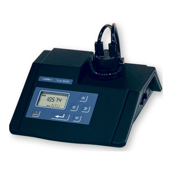
- Page 1 Operating Manual Turb 555 / Turb 555 IR Turbidity measuring instrument ba41113e07 04/2009...
- Page 2 Turb 555 / Turb 555 IR Accuracy when The use of advanced technology and the high quality stan- going to press dard of our instruments are the result of a continuous devel- opment. This may result in differences between this operating manual and your instrument.
-
Page 3: Table Of Contents
Contents Turb 555 / Turb 555 IR - Contents Overview ....... 5 1.1 Operation pad . - Page 4 Contents Turb 555 / Turb 555 IR 4.5 Setting up the instrument ..... 47 4.5.1 General information ....47 4.5.2...
-
Page 5: Overview
Turb 555 / Turb 555 IR Overview Overview The Turb 555 / Turb 555 IR lets you perform turbidity mea- surements easily and reliably. The measuring method used in the Turb 555 IR corresponds to the ISO 7027 / DIN 27027. The measuring method used in the Turb 555 follows the US EPA construction recommen- dations. -
Page 6: Operation Pad
Overview Turb 555 / Turb 555 IR Operation pad The Turb 555 / Turb 555 IR is operated via a 6 key touch pad and a display (LCD): Function Switch the measuring instrument on/off Confirm input Save/output measured value Increase values... -
Page 7: Display
Turb 555 / Turb 555 IR Overview Display The display is integrated in the touch pad. It has the follow- ing possible indications: Code symbol: Prompt to input the code Measured value User guidance symbols Unit (only active during calibration) -
Page 8: Sockets
Overview Turb 555 / Turb 555 IR Sockets Socket for plug-in power supply unit Dry air purge system inlet Dry air purge system outlet RS232 interface Plug-in power supply unit ba41113e07 04/2009... -
Page 9: Safety
Turb 555 / Turb 555 IR Safety Safety This operating manual contains basic instructions that you must follow during the commissioning, operation and main- tenance of the measuring instrument. Consequently, all re- sponsible personnel must read this operating manual before working with the measuring instrument. -
Page 10: Authorized Use
Safety Turb 555 / Turb 555 IR Authorized use This instrument is authorized exclusively for turbidity mea- surements in the laboratory. The technical specifications as given in chapter T ECHNICAL , must be observed. Only the operation and running of the measuring instrument according to the instructions given in this operating manual is authorized. - Page 11 Turb 555 / Turb 555 IR Safety Safe operation If safe operation is no longer possible, the instrument must be taken out of service and secured against inadvertent op- eration! Safe operation is no longer possible if the measuring instru-...
- Page 12 Safety Turb 555 / Turb 555 IR ba41113e07 04/2009...
-
Page 13: Commissioning
Turb 555 / Turb 555 IR Commissioning Commissioning Scope of delivery Turb 555 or Turb 555 IR laboratory measuring instrument with short instructions Operating manual Universal plug-in power supply unit with country-specific adapters Plastic box with 4 calibration standards (0.02 / 10 / 100 /... -
Page 14: Connecting The Plug-In Power Supply Unit
Turb 555 / Turb 555 IR Connecting the plug-in power supply unit 1 Plug the original WTW plug-in power supply unit (3) into the socket (1) of the measuring instrument. 2 Plug the suitable adapter (2) into the plug-in power supply unit. -
Page 15: Switching On The Measuring Instrument
Turb 555 / Turb 555 IR Commissioning Switching on the measuring instrument 1 Place the measuring instrument on a flat surface and protect it from intense light and heat. 2 Press the key. The measuring instrument automatically switches to the measuring mode: A measured value and the display appear. - Page 16 Commissioning Turb 555 / Turb 555 IR ba41113e07 04/2009...
-
Page 17: Operation
Turb 555 / Turb 555 IR Operation Operation Instructions for operating 4.1.1 Marking and aligning cuvettes Even completely clean quality cuvettes exhibit tiny direction- al differences in their light transmittance. Therefore, each cuvette should be marked - both the measuring cuvettes as well as the cuvettes with the calibration standards (refer to section 2130 of the "Standard Methods for the Examination... - Page 18 Operation Turb 555 / Turb 555 IR Note Always use the cuvette and the light protection cap together; only in this way is the cuvette marked. Aligning a marked A marked cuvette is aligned as follows: cuvette 1 Insert the cuvette in the cuvette shaft of the turbidi- meter.
-
Page 19: Venting The Sample
Turb 555 / Turb 555 IR Operation 4.1.2 Venting the sample Air bubbles in the sample affect the measuring result to a massive extent because they have a large scattering effect on the incident light. Larger air bubbles cause sudden changes in the measured values whereas smaller air bub- bles are recorded by the instrument as turbidity. -
Page 20: Measuring Turbidity
Operation Turb 555 / Turb 555 IR Measuring turbidity 4.2.1 Measuring methods of the Turb 555 and Turb 555 IR Measuring system The measuring system consists of a light source, the cuvette with the sample, a beam splitter and a total of four light de-... - Page 21 Turb 555 / Turb 555 IR Operation Measuring methods The Turb 555 /Turb 555 IR can measure with different mea- suring methods. To do so, the measuring signals of the four detectors are evaluated differently. Nephelometric The rays of the undissolved particles (90°...
- Page 22 Operation Turb 555 / Turb 555 IR You can select the following measuring units (see section 4.5.2 S ETTINGS Measuring units NTU = Nephelometric Turbidity Units (90°scattered light Turb 555 measurement). Nephelometric turbidity unit according to section 2130 of the "Standard Methods for the Examina- tion of Water and Wastewater", 19th edition.
-
Page 23: Single Measurements
Turb 555 / Turb 555 IR Operation 4.2.2 Single measurements Preparatory activi- Perform the following preparatory activities when you want ties to measure (see section 3.3 S WITCHING ON THE MEASURING INSTRUMENT 1 Switch on the measuring instrument. 2 Wait until the warm-up period is over. - Page 24 Operation Turb 555 / Turb 555 IR 5 Insert the cuvette in the cuvette shaft of the turbidi- meter. 6 Align the cuvette (see section 4.1.1 M ARKING AND ALI GNING CUVETTES 7 Wait for a stable measured value and read it.
-
Page 25: Measuring Turbidity Using The Pour-Through Vessel (Accessory)
4.2.3 Measuring turbidity using the pour-through vessel (accessory) The pour-through vessel (WTW order number 600600) fits any Turb 555 /Turb 555 IR instrument and enables you to measure several samples one after the other quickly and easily. Any interference effects caused by air bubbles are reduced. - Page 26 Operation Turb 555 / Turb 555 IR Preparatory Switch on your instrument before installing the pour-through activities vessel. Thus, the warm-up period of your instrument will be over after the installation and you will be able to start mea- suring immediately (warm-up period, see section 3.3 S...
- Page 27 Turb 555 / Turb 555 IR Operation To install the pour-through vessel, proceed as follows: 1 Pull the white marker pin out of the locking collar (2) of the cuvette shaft. 2 Using the spanner wrench provided (8), unscrew and remove the locking collar (2).
- Page 28 Operation Turb 555 / Turb 555 IR Note The pour-through vessel can remain installed until the next calibration. Note If you use the pour-through vessel, you do not need to rinse the cuvette 3x with the sample. The sample rinses the cu- vette as it flows through.
-
Page 29: Measuring Turbidity Using The Flow-Through
4.2.4 Measuring turbidity using the flow-through vessel (accessory) The flow-through vessel (WTW order number 600605) fits to each Turb 555 /Turb 555 IR instrument and enables you to continuously measure a sample flowing through and to no- tice turbidity changes immediately. Using the periodical measured value output, you can output the current mea- sured values periodically to a printer or PC connected. - Page 30 Operation Turb 555 / Turb 555 IR Preparatory activi- Switch on your instrument before installing the flow-through ties vessel. Thus, the warm-up period of your instrument will be over after the installation and you will be able to start mea- suring immediately (warm-up period, see section 3.3 S...
- Page 31 Turb 555 / Turb 555 IR Operation To install your flow-through vessel, proceed as follows: 1 Pull the white marker pin out of the locking collar (2) of the cuvette shaft. 2 Using the spanner wrench provided (10), unscrew and remove the locking collar (2).
- Page 32 Operation Turb 555 / Turb 555 IR 15 Attach the tubes to the flow-through vessel by screw- ing the nuts to the threads of the flow-through vessel. When doing so, observe the marking of the threads: in = inlet, out = outlet.
- Page 33 Turb 555 / Turb 555 IR Operation Connecting the Proceed as follows: cuvette shaft purging 1 Connect the purging gas source to the fitting (1) on the back of the instrument using a suitable hose. 2 Turn on the purging gas.
-
Page 34: Access Codes
Turb 555 / Turb 555 IR Access codes 4.3.1 General information The Turb 555 /Turb 555 IR has a code function with two dif- ferent access codes: Calibration code to protect the calibration data Setup code to protect the instrument configuration Measured values that were determined while the code func- tion was active are given the "QC"... - Page 35 Turb 555 / Turb 555 IR Operation Entering the codes To enter the calibration or setup code, proceed as follows: 1 With the key set the first digit of the code. 2 Press 3 With the key set the second digit of the code.
-
Page 36: Calibration
4.4.1 Basic information on calibration Why calibrate? As for any measuring instrument, the measuring accuracy of the Turb 555 /Turb 555 IR has to be checked and adjusted at regular intervals. When to calibrate? Under normal conditions, we recommend to calibrate the measuring instrument at least every three months. -
Page 37: Calibration Procedures
Turb 555 / Turb 555 IR Operation 4.4.2 Calibration procedures You have the following possibilities to calibrate the Turb 555 /Turb 555 IR: Five-point calibration according to the preset calibration program (section 4.4.4). To achieve the accuracy speci- fied in the Technical Data in the whole measuring range you have to carry out this calibration. -
Page 38: Preparing The Calibration
Operation Turb 555 / Turb 555 IR If there are more possible calibration points between the start and end of the calibration interval, they must be used. Always carry out the calibration in the sequence from the highest to the lowest value. -
Page 39: Five-Point Calibration
Turb 555 / Turb 555 IR Operation 4.4.4 Five-point calibration Calibration For the five-point calibration according to the calibration pro- sequence gram, the instrument is calibrated with the following calibra- tion standards in the following sequence: 0.02 > 1750 > 10000 > 100 > 10 > 0.02 NTU... - Page 40 Operation Turb 555 / Turb 555 IR 4 Insert the 0.02 NTU calibration standard into the cu- vette shaft. 5 Align the cuvette. 6 Press the key. During the calibration step, the sym- bols flash. The lower display line shows the remain- ing measuring cycles until the end of the calibration step.
- Page 41 Turb 555 / Turb 555 IR Operation 9 Align the cuvette. 10 Press the key. During the calibration step, the sym- bols flash. The lower display line shows the remain- ing measuring cycles until the end of the calibration step.
- Page 42 Operation Turb 555 / Turb 555 IR 16 Insert the 100 NTU calibration standard into the cu- vette shaft. 17 Align the cuvette. 18 Press the key. During the calibration step, the sym- bols flash. The lower display line shows the remain- ing measuring cycles until the end of the calibration step.
- Page 43 Turb 555 / Turb 555 IR Operation 22 Press the key. During the calibration step, the sym- bols flash. The lower display line shows the remain- ing measuring cycles until the end of the calibration step. Then, the calibration step is carried out once more.
- Page 44 Operation Turb 555 / Turb 555 IR Terminating the To terminate the calibration process before the scheduled calibration end, proceed as follows: prematurely 1 Wait until the current calibration step is finished and the instrument asks you to insert the next calibration standard.
-
Page 45: User-Defined Calibration
Turb 555 / Turb 555 IR Operation 4.4.5 User-defined calibration Calibration This is how you calibrate your measuring instrument accord- ing to a procedure selected by you: 1 In the normal measuring mode, press the until the indicator appears on the left part of the display. - Page 46 Operation Turb 555 / Turb 555 IR 9 Wait until the calibration step is finished. The instrument asks you to insert the next calibration standard according to the calibration program. 10 Repeat the steps 5 to 9 until all required calibration standards have been measured.
-
Page 47: Setting Up The Instrument
Operation Setting up the instrument 4.5.1 General information In the normal measuring mode, you can adjust the Turb 555 /Turb 555 IR to your requirements using the setup function at any time. You can alter the following settings: Measuring procedure / measured unit... -
Page 48: Settings
4.2.1. 4 Press the key to select the required unit. Options: Turb 555: NTU -> EBC -> NEPHELO Turb 555 IR: NTU -> FNU -> FAU 5 Confirm your selection with ba41113e07 04/2009... - Page 49 Turb 555 / Turb 555 IR Operation Ratio In the following menu, you can select the measurement ac- cording to the Ratio method ( is displayed). For more detailed information on the Ratio method, see section 4.2.1. 6 Press the key to switch the measurement ac- cording to the Ratio method on or off.
- Page 50 Operation Turb 555 / Turb 555 IR Code function In the following menu, you can activate/deactivate the code function and change the calibration or setup code (Code is displayed in the upper display line). Note When the code function is activated, all measured values output to the printer/PC are given the "QC"...
- Page 51 Turb 555 / Turb 555 IR Operation Changing the You can change the calibration code in the following menu calibration code (C is displayed): 12 With the key change the first digit of the code. 13 Press 14 With the key change the second digit of the code.
- Page 52 Operation Turb 555 / Turb 555 IR 20 Repeat the steps 12 to 18. 21 Confirm the setup code with The next setup menu appears ( Periodical measured In the following menu, you can switch the periodical mea- value output...
- Page 53 Turb 555 / Turb 555 IR Operation Setting the baud To select the baud rate proceed as follows: rate 24 With the key select the required baud rate. Options: 1200 -> 2400 -> 4800 -> 9600 25 Confirm your selection with...
- Page 54 Operation Turb 555 / Turb 555 IR 26 To change the calibration interval, press until the required number of days is displayed. Options: 0.0 ... 180 If you do not want to be automatically reminded when a calibration is due, select 0.0.
- Page 55 Turb 555 / Turb 555 IR Operation Day and month In the following menu, you can set the day and month is displayed). The month display flashes. OFFSET SCALE AUTO mg/l NEPH SETUP MEMORY TIME DAY:MONTH YEAR BAUD ERROR STORE...
- Page 56 Operation Turb 555 / Turb 555 IR Time In the following menu, you can set the time ( is dis- played). The hour display flashes. 34 To change the hour, press 35 Confirm your selection with . The minute display flashes.
- Page 57 Turb 555 / Turb 555 IR Operation End of the After the time has been input, the END display appears in setup program the lower display line. 38 Terminate the setup program with . The instru- ment saves the new settings and returns to the nor- mal measuring mode.
-
Page 58: Resetting To Default Settings (Reset)
Operation Turb 555 / Turb 555 IR 4.5.3 Resetting to default settings (Reset) Default settings In a reset, the following functions are reset to the default set- tings (initialized): Setting point Default setting Unit Ratio method Resolution 0.01 NTU Code function... -
Page 59: Documentation
Turb 555 / Turb 555 IR Operation Documentation When the instrument is connected to a printer or PC as an output device, you can record measured values. Information on suitable cables or the printer can be found in chapter 8... - Page 60 Operation Turb 555 / Turb 555 IR Time base The output times always refer to a full hour of the selected time. Samples: Current time Calibration First measured interval value at 11:59 30 min 12:00 12:02 30 min 12:30 12:02...
-
Page 61: Calibration Record
Turb 555 / Turb 555 IR Operation 4.6.3 Calibration record If a printer or PC is connected and switched on, a calibration record is automatically output at the end of the calibration. Sample printout: Date: 29 Mar 2000 14:04:37 Calibration... - Page 62 Operation Turb 555 / Turb 555 IR ba41113e07 04/2009...
-
Page 63: Maintenance, Cleaning, Disposal
Turb 555 / Turb 555 IR Maintenance, cleaning, disposal Maintenance, cleaning, disposal Replacing the lamp module The lamp module can easily be replaced if it is defective. You will find the order number for the spare lamp module in chapter 8 A . -
Page 64: Cleaning
Maintenance, cleaning, disposal Turb 555 / Turb 555 IR 6 Insert the new lamp module (lamp symbol must be vertical), so that it locks into place and a click can be heard. 7 Connect the instrument to the mains supply and switch it on. -
Page 65: Disposal
Turb 555 / Turb 555 IR Maintenance, cleaning, disposal Disposal Packing This measuring instrument is sent out in a protective trans- port packing. We recommend: Keep the packing material in case you have to send the measuring instrument back for service. - Page 66 Maintenance, cleaning, disposal Turb 555 / Turb 555 IR ba41113e07 04/2009...
-
Page 67: What To Do If
Turb 555 / Turb 555 IR What to do if... What to do if... "- - - - -" display Cause Remedy – The instrument is – Wait for a stable measuring but the measured value measured value is not yet stable –... - Page 68 What to do if... Turb 555 / Turb 555 IR Measured values Cause Remedy that are obviously – Cuvette contaminated – Clean the cuvette too high – Cuvette scratched – Replace the cuvette – Cuvette misted up – Regulate the temperature...
- Page 69 Turb 555 / Turb 555 IR What to do if... Warning message Cause Remedy W-02, – Wrong or erroneous – Repeat the calibration W-03, calibration standards using the correct W-04, used, or calibration standards W-05, – Instrument error – Check the lamp or WNG –...
- Page 70 What to do if... Turb 555 / Turb 555 IR Error message Cause Remedy E-01 or SFE – Severe instrument error – Have the instrument repaired by the WTW service department The instrument does Cause Remedy not react on key- –...
-
Page 71: Technical Data
Turb 555 / Turb 555 IR Technical data Technical data Ambient Storage - 25 °C ... + 65 °C temperature Operation +10 °C ... + 50 °C Power supply Plug-in power supply Friwo FW7207/15 unit Friwo Part-No. 1812285 Input: 100 - 240 V 10% / ~ ±... - Page 72 Technical data Turb 555 / Turb 555 IR Measuring ranges Unit Turb 555 Turb 555 IR 0 - 10 000 0 - 10 000 0 - 10 000 0 - 2 450 0 - 2 450 NEPHELO 0 - 67 000...
- Page 73 Turb 555 / Turb 555 IR Technical data Test certificates CE, cETLus Other data Automatic self-check Integrated real-time clock GLP function (calibration interval monitoring) Safety access codes for calibration and instrument setup ba41113e07 04/2009...
- Page 74 Technical data Turb 555 / Turb 555 IR ba41113e07 04/2009...
-
Page 75: Accessories, Options
Turb 555 / Turb 555 IR Accessories, Options Accessories, Options Turb 555 Description Model Order Set of calibration Kal. Kit P Turb 555 600545 standards for Turb 555 0.02 / 10.0 / 100 / 1750 NTU 10000 NTU calibra- Kal.-Std. 10000 NTU... - Page 76 Accessories, Options Turb 555 / Turb 555 IR General accessories Description Model Order Pour-through vessel D-Turb 600600 Flow-through vessel Flow-Turb 600605 Empty cuvettes, set Cell Turb/SET 600601 of 3 pieces Cuvette holder for KS-Turb 600602 6 cuvettes, collaps- ible Cable to connect to a...
-
Page 77: Lists
Turb 555 / Turb 555 IR Lists Lists This chapter provides additional information and orientation aids. Abbreviations The list of abbreviations explains abbreviations that appear on the display or when dealing with the instrument. Index The index helps you to find the topics that you are looking for. - Page 78 Lists Turb 555 / Turb 555 IR Abbreviations Auto Automatic measuring mode Calibration Measuring range exceeded European Brewery Convention Units Nephelometric turbidity units Formazin turbidity units Nephelometric Formazin units Formazin attenuation units W01 - W05 Warning message (see W ...)
- Page 79 Turb 555 / Turb 555 IR Index Index Adapter Date ..........14 ............47 Air bubbles Day and month setting ...........19 ....... 55 Authorized use Default condition ........10 ......... 58 Default settings ........58 DIN/ISO measurements ....37 Background illumination Dry air purge system .......7...
- Page 80 Index Turb 555 / Turb 555 IR system ..........33 Nephelo ..........22 ............22 Target group .......... 9 Time ............. 47 Obligations of the operator ....11 Operating safety ......... 10 Warm-up period ......15, 23 Options ..........75 Output device ........
- Page 82 Wissenschaftlich-Technische Werkstätten GmbH Dr.-Karl-Slevogt-Straße 1 D-82362 Weilheim Germany Tel: +49 (0) 881 183-0 +49 (0) 881 183-100 Fax: +49 (0) 881 183-420 E-Mail: Info@WTW.com Internet: http://www.WTW.com...
Need help?
Do you have a question about the Turb 555 and is the answer not in the manual?
Questions and answers