
Related Manuals for wtw Turb 550


Summary of Contents for wtw Turb 550
- Page 1 Operating Manual Turb 550 / Turb 550 IR Turbidity Measuring Instrument ba41112e03 04/2003...
- Page 2 Copyright Weilheim 2002, WTW GmbH & Co. KG © Reprinting - even in the form of excerpts - is only allowed with the explicit written authorization of WTW GmbH &...
-
Page 3: Table Of Contents
List of contents Overview ....... 5 1.1 Keypad ....... .6 1.2 Display . - Page 4 List of contents 5.2.2 Cleaning the cells ....40 5.3 Disposal .......41 What to do if ...
-
Page 5: Overview
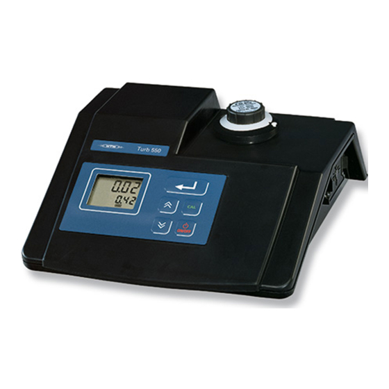
Overview Overview The Turb 550 / Turb 550 IR lets you perform turbidity mea- surements rapidly and reliably. The measuring method used in the Turb 550 IR corresponds to the ISO 7027 / DIN 27027. The measuring method used in the Turb 550 follows the US EPA construction recommen- dations. -
Page 6: Keypad
Overview Keypad Store/output the measured value Increase values; Select settings Reduce values; Select settings Call up/terminate calibra- tion procedure Switch measuring instru- ment on/off... -
Page 7: Display
Overview Display Upper display line: Meas. value display in NTU / operating guide Lower display line: Stored meas. value / operating guide / error messages Status displays Operating guide on setting up LoBat: Request to change the battery Sockets RS232 interface Socket for plug-in power supply Plug-in power supply... - Page 8 Overview...
-
Page 9: Safety
Safety Safety This operating manual contains basic instructions that you must follow during the commissioning, operation and main- tenance of the instrument. Consequently, all responsible personnel must read this operating manual before working with the instrument. The operating manual must always be available within the vicinity of the instrument. -
Page 10: Authorized Use
Safety Authorized use This instrument is authorized exclusively for use in measur- ing turbidity in the laboratory. The technical specifications as given in the chapter, T ECHNI , must be observed. Only the operation and run- ning of the measuring instrument according to the instructions given in this operating manual is authorized. - Page 11 Safety In you are in any doubt, please contact the supplier of the in- strument. Obligations of the The operator of this measuring instrument must ensure that operator the following laws and guidelines are observed when using dangerous substances: EEC directives for protective labor legislation National protective labor legislation Safety regulations Safety datasheets of the chemical manufacturer...
- Page 12 Safety...
-
Page 13: Commissioning
Commissioning Commissioning Scope of delivery Turb 550 or Turb 550 IR laboratory measuring instrument with short instructions card Operating manual Universal plug-in power supply with country-specific adapter ZBK accessory case with 3 calibration standards, 2 empty cells, 5 marker rings, cell cleaning cloths... -
Page 14: Connecting The Plug-In Power Supply
Commissioning Connecting the plug-in power supply 1 Plug the original WTW plug-in power supply (1) into the socket (3) of the measuring instrument 2 Plug in the appropriate adapter (2) to the plug-in pow- er supply 3 Connect the plug-in power supply to an easily acces-... -
Page 15: Switching On The Measuring Instrument
Commissioning Switching on the measuring instrument 1 Place the measuring instrument on a flat surface and protect it against intensive light and heat 2 Press the key. All the display elements appear briefly on the display. The measuring instrument then switches automati- cally to the measuring mode: A measured value and the Auto display appear 3 Set the date and time, if necessary (see 4.4.1 C... - Page 16 Commissioning...
-
Page 17: Operation
Operation Operation Instructions for operating 4.1.1 Marking and aligning cells Even completely clean quality cells exhibit tiny differences in their light transmittance. Therefore, we recommend marking each cell (both measuring cells as well as cells with the cal- ibration standard). Consequently, each cell can always be inserted in the correct position and you can achieve precise measuring results. - Page 18 Operation Aligning a marked A marked cell is aligned as follows: cell 1 Insert the cell in the cell shaft on the turbidity measur- ing instrument 2 Align the marked cell so that the arrow on the marker ring points to the marker pin on the casing of the cell shaft.
-
Page 19: Venting The Sample
Operation 4.1.2 Venting the sample Air bubbles in the sample affect the measuring result to a massive extent because they have a large scattering effect on the incident light. Larger air bubbles cause sudden changes in the measured values whereas smaller air bub- bles are recorded by the instrument as turbidity. -
Page 20: Measuring Turbidity
Operation Measuring turbidity 4.2.1 Standard measurement Preparatory Perform the following preparatory activities when you want activities to begin measuring: Switch on the instrument 2 Wait for at least 30 minutes to allow for the warm-up time. Note Incorrect calibration of the turbidity measuring instrument re- sults in incorrect measured values. - Page 21 Operation 6 Align the cell (see 4.1.1 M ARKING AND ALIGNING CELLS 7 The turbidity value appears in nephelometric turbidity units (NTU) on the display. The instrument automati- cally selects the measuring range and resolution 8 If you want to measure and compare more than one sample, press the key.
- Page 22 Operation If the print function is switched on and a printer or PC is con- nected and switched on, the time, date and measured value will be output by pressing Sample printout 13:17 15 JAN 1999 19.09 NTU 13:18 15 JAN 1999 756 NTU...
-
Page 23: Measuring Turbidity Using The Flow-Through Vessel (Accessory)
4.2.2 Measuring turbidity using the flow-through vessel (accessory) The flow-through vessel (WTW order number 600 600) fits any Turb 550 instrument and enables you to measure sev- eral samples one after another quickly and easily. Any inter- ference effects caused by air bubbles are reduced. Besides, you do not have to use balanced cells for comparative mea- surements as always the same cell is used. - Page 24 Operation Installing a flow- To install the flow-through vessel, proceed as follows: through vessel 1 Pull the white marker pin out of the casing (2) of the cell shaft 2 Unscrew and remove the casing (2) using the tighten- ing key (8) provided 3 Place the fixing ring (1) on the cell shaft 4 Reattach the casing (2) and tighten it up using the tightening key (8)
- Page 25 Operation Note The flow-through vessel can remain installed until the next calibration.
- Page 26 Operation Note If you use the flow-through vessel, you do not need to rinse the cell 3x with the sample. The sample rinses the cell as it flows through. Even the forming of air bubbles is consider- ably reduced. Measuring 1 Remove the cover from the flow-through vessel 2 Slowly pour approximately 500 ml sample into the container of the flow-through vessel.
-
Page 27: Calibration
Operation Calibration Why calibrate? As with every measuring instrument, the measuring accura- cy of the turbidity measuring instrument must be checked and adjusted at regular intervals. For this purpose, 3 calibration standards (1000 NTU, 10 NTU, 0.02 NTU) that were specially developed for this in- strument are supplied with the instrument. - Page 28 Operation Calibration How to calibrate your measuring instrument: 1 Press the key. The Ident display and the Cal dis- play appear. The number 1000 appears in the lower display line 2 Insert the 1000 NTU calibration standard in the cell shaft 3 Align the cell and wait for a stable measured value 4 Press the...
- Page 29 Operation 7 Press the key. The Store display flashes for approximately 3 sec- onds. The number 10.0 (NTU) appears in the upper display line. The number 0.02 (NTU).appears in the lower display line 8 Insert the 0.02 NTU calibration standard in the cell shaft 9 Align the cell and wait for a stable measured value 10 Press the...
- Page 30 Operation the immediate vicinity of the calibration point. For a 2 point calibration, you must use 2 calibration stan- dards next to each other. Measuring is then possible with a reduced accuracy between the calibration points. To achieve the precision specified in the technical data, you must perform the calibration using all 3 calibration standards in the specified sequence.
-
Page 31: Configuring The Instrument
Operation Configuring the instrument 4.4.1 Changing settings You can perform the following settings: Date (YYYY/MM/DD) Time (min/sec) Calibration interval (1 - 99 days) After the set calibration interval expires, the Cal message appears on the display until the measuring instrument has been recalibrated). - Page 32 Operation 2 To change the year, press 3 Confirm by pressing . The instrument automati- cally shows the next possible setting, the date. The Day.Month message appears and the number of the month flashes 4 To change the month, press and confirm by pressing The number of the day flashes...
- Page 33 Operation 7 To change the calibration intervals, press til the required number of days is displayed 8 Confirm by pressing . The Prt (printing) mes- sage appears 9 To switch the print function to on (On) or off (OFF), press until the required setting is displayed 10 Confirm by pressing .
-
Page 34: Reset
Operation 4.4.2 Reset Basic settings The following functions are reset to the delivery status (ini- tialized) if a Reset is performed: Setting point Delivery status Calibration interval 30 days Printing Baud 4800 To reset the settings, proceed as follows: 1 Press the key and hold it down 2 Press the key. -
Page 35: Documentation
Operation Documentation If the instrument is connected to a printer or PC, the mea- sured values can be documented via the printer or PC. In- formation on suitable cables and the printer is given in 8 CCESSORIES OPTIONS 4.5.1 Connecting the printer 1 Plug the printer cable into the RS232 interface (1) of the instrument 2 Connect the printer cable to the printer... - Page 36 Operation Sample printout 13:17 15 JAN 1999 19.09 NTU 13:18 15 JAN 1999 756 NTU Note After calibration, if the print function is switched on and a printer is connected, the calibration protocol is printed out automatically. Sample printout DATE: 15 JAN 1999 13:20 Current date...
-
Page 37: Maintenance, Cleaning, Disposal
Maintenance, cleaning, disposal Maintenance, cleaning, disposal Maintenance The measuring instrument is largely maintenance-free. The maintenance required consists merely of changing the lamp module and replacing the batteries. 5.1.1 Changing the lamp module 1 Switch off the measuring instrument and disconnect it from the mains 2 Take out the lamp module (1): Press the two grips gently together and carefully pull out the lamp mod-... -
Page 38: Changing The Batteries
Maintenance, cleaning, disposal 5 Stow the wires in the opening (3) of the measuring in- strument again. Make sure that the wires are not placed in front of the lamp and that they are not in the way of the lamp module 6 Insert the new lamp module (lamp symbol must be vertical) so that it locks into place and a click can be heard... - Page 39 Maintenance, cleaning, disposal 7 Remove the underside of the housing and lay it to one side 8 Remove the two old batteries (1) and dispose of them (see 5.3 D ISPOSAL 9 Insert two new batteries (CR3032 lithium batteries) so that the positive poles point towards the clip of the battery holder 10 Reattach the underside of the housing and guide the plug-in connector for the lamp module through the...
-
Page 40: Cleaning
Maintenance, cleaning, disposal 15 Calibrate the instrument (see 4.4 C ). The ALIBRATION instrument is now ready for operation again. Cleaning 5.2.1 Cleaning the measuring instrument Occasionally wipe the outside of the measuring instrument with a damp, lint-free cloth. Disinfect the housing with iso- propanol as required. -
Page 41: Disposal
Maintenance, cleaning, disposal Disposal Packing The measuring instrument is sent out in a protective trans- port packing. We recommend: Keep the packing material in case you have to send the measuring instrument back for service. The original packing prevents the measuring instrument from being damaged during transport. - Page 42 Maintenance, cleaning, disposal...
-
Page 43: What To Do If
What to do if ... What to do if ... Error message Cause Remedy E-01 – Wrong calibration – Use the correct calibration standard used standard – The lamp is defective – Replace the lamp module Error message Cause Remedy E-02 or E-03 –... - Page 44 What to do if ... “LoBat” display Cause Remedy flashes – The backup batteries – Change the batteries (see are almost empty 5.1.2 C HANGING THE BATTERIES Cause Remedy “Cal” display flashes – The calibration interval – Calibrate the instrument set up has expired (see 4.3 C ALIBRATION...
- Page 45 Cause Remedy does not react to – No energy supply – Connect the plug-in power pressing the keys supply with the measuring instrument and the mains power supply Note If a fault cannot be remedied, send the instrument to WTW.
- Page 46 What to do if ...
-
Page 47: Technical Data
Width 252 mm instrument Height 100 mm Weight 1 kg Sample temperature 10 - 40 °C Measuring principle Nephelometric Light source Turb 550 Tungsten lamp Turb 550 IR IR LED Measuring range NTU (= FTU = FNU) 0 - 1000... - Page 48 Technical data For the range, Resolution 0.01 - 9.99 NTU 0.01 NTU For the range, 10.0 - 99.9 NTU 0.1 NTU For the range, 100 - 1000 NTU 1 NTU ± 2% of the measured value or ± 0.01 NTU Accuracy (±...
-
Page 49: Accessories (Options)
Cell Turb/SET 600601 suring instrument, 3 pieces Cell holder for 6 cells KS-Turb 600602 Spare lamp module for Lamp Turb 550 600603 Turb 550 Spare lamp module for Lamp Turb 550- 600604 Turb 550 IR Cable to connect to a printer... - Page 50 Accessories (options)
-
Page 51: Abbreviations And Index
Abbreviations and index Abbreviations and index This chapter contains additional information and orientation aids. Abbreviations The list of abbreviations describes displays and abbrevia- tions that may be encountered when using the measuring in- strument. Index The index helps you find specific information. - Page 52 Abbreviations and index List of abbreviations ARng AutoRange: Automatic range switching; Measuring instrument measures at the highest possible resolution Auto Automatic measuring mode Calibration E1 - E5 Error message (see W ...) HAT TO DO IF Nephelometric turbidity units Formazin turbidity units Nephelometric formazin units LoBat Low Battery:...
- Page 53 Abbreviations and index Index adapter mark a cell air bubbles measuring accuracy adjustment aligning a marked cell measuring accuracy check aligning an unmarked cell measuring range selection authorized use operational safety balancing cells options basic settings baud rate print function 22, 31, 35 printing calibration interval...
- Page 54 Abbreviations and index...
Need help?
Do you have a question about the Turb 550 and is the answer not in the manual?
Questions and answers