
Related Manuals for wtw Turb 2000


Summary of Contents for wtw Turb 2000
- Page 1 Operating manual Turb 2000 Series: Turb 2000 Turb 2020 Turb 2100 Turb 2110 Turb 2120 Process Turbidimeter ba75695e03 10/2013...
- Page 2 The latest version of the present operating manual can be found on the Internet under www.WTW.com. Copyright © Weilheim 2013, WTW GmbH Reprinting - even as excerpts - is only allowed with the explicit written authorization of WTW GmbH, Weilheim.
-
Page 3: Table Of Contents
Turb 2000 Series Overview Contents Overview ............................5 The Turb 2000 Series ......................5 Unpacking and inspection of the instrument and accessories ..........5 The display ..........................6 Keypad ........................... 6 Vapor purge ..........................7 Safety .............................. 8 Installation and commissioning ......................10 Mounting and site selection .................... - Page 4 Overview Turb 2000 Series 6.18 Saving configuration settings ....................32 Additional features and options ....................33 Ultrasonic cleaning (Turb 2020 and 2120) ................33 RS-485 outputs ........................34 7.2.1 Simple communication ....................34 7.2.2 Modbus communication .................... 34 Flow alarm ..........................34 Flow controller ........................
-
Page 5: Overview
The Turb 2000 Series process turbidimeter allows for the measurement of the turbidity of drinking water and process water on-line. The White Light Turb 2000 and 2020 has been designed to meet the design criteria specified by the US EPA 180.1 on turbidity measurement. The infrared Turb 2100 and 2120 was designed to meet the design criteria specified in ISO 7027 and DIN 27027 for the measurement of the turbidity of a sample. -
Page 6: The Display
Overview Turb 2000 Series The display Figure 1 illustrates all the items that can appear on the display. The upper row of the display (1) is used for reporting the turbidity levels and to provide user guidance in the customer setting routine. The lower row of the display (2) is used to communicate error messages and provide user guidance. -
Page 7: Vapor Purge
Overview Vapor purge The Turb 2000 series is equipped with a continuous vapor purge system. A replaceable desiccant pouch in the lower portion of the instrument dries the air. System heat is used to warm the air. A fan inside the instrument continuously circulates heated dry air around the optical well and the flow through cuvette. -
Page 8: Safety
Safety Turb 2000 Series Safety This operating manual contains basic instructions that you must follow during the commissioning, operation and maintenance of the turbidimeter. Consequently, all responsible personnel must read this operating manual before working with the sampler. The operating manual must always be available within the vicinity of the turbidimeter. - Page 9 Turb 2000 Series Safety Technical data. Safe operation If safe operation is no longer possible, the instrument must be taken out of service and secured against inadvertent operation! Safe operation is no longer possible if the turbidimeter • has been damaged in transport •...
-
Page 10: Installation And Commissioning
The installation dimensions of the instrument are given in figure 3. The following screws are required for installation: M6 for the housing, M4 for the field terminal box. The Turb 2000 series is designed to have the field terminal box cradled under the sensor portion of the instrument. It is recommended that the field terminal box be mounted first, and then the rest of the instrument be mounted on top. -
Page 11: Plumbing
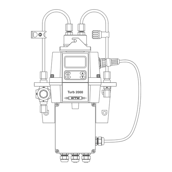
Turb 2000 Series Installation and commissioning Plumbing Figure 4 shows the plumbing recommended for the instrument. The instrument requires only a very low minimum pressure for operation. A flow controller and backpressure valve are integrated in the instrument. For details, see chapter Technical data. -
Page 12: Drain Vent
Turb 2000 Series 2.2.1 Drain vent The Turb 2000 series has been fitted with a drain vent (Pos.9) in the “OUT” bulkhead fitting. This fitting allows for atmospheric equalization, thus helping to alleviate bubble formation in the cuvette. Refer to Figure 4. -
Page 13: Electrical Connections
Turb 2000 Series Installation and commissioning Electrical connections WARNING • Only qualified electricians should be allowed to perform the installation of the instrument as it involves a line voltage that could endanger life. • The electrician must have read and understood this manual and must follow the instructions in this manual. -
Page 14: Power Supply
Installation and commissioning Turb 2000 Series Figure 5: Electrical connections for the instrument Power supply terminal block Power cable strain relief Power cable bulkhead Alarms terminal block 240 V AC, 2A 4 – 20 mA / RS485 plug with screw terminals Sensor wiring 4 –... -
Page 15: Rs-485
2A. Please note that the relays are labeled NO (Normally Open), NC (Normally Closed) and C (Common). As these alarms are configured fail-safe, the normal condition is with power applied to the Turb 2000 series and in a non-alarm condition. Operation of these alarms is covered in section 6.5 C... -
Page 16: Operation
Operation Turb 2000 Series Operation This process turbidimeter allows for the on-line measurement of the turbidity of process water, swimming pool water and drinking water. The turbidity of the water is usually reported in Nephelometric Turbidity Units (NTU), but may be reported in Formazin Nephelometric Units (FNU). Readings above 1100 NTU will cause the display to flash indicating an over range condition.Readings above 1100 NTU... - Page 17 Turb 2000 Series Operation The security code (333) must be entered to gain access to CAL or CONFIG menus. Notice that the first number in the code is flashing; the flashing indicates that this is the number to be changed. Use the ...
-
Page 18: Instrument Calibration
Calibration standards If the Turb 2000 series will be used over the entire range of 0.02 to 1000 NTU a complete calibration as described below will be required. If instrument accuracy is only required below 10 NTU (below 1 NTU for Turb 2110), such as potable water, a calibration may be performed using only a 10 NTU and a 0.02 NTU standard (1.0 NTU and... -
Page 19: Calibration Procedures
Calibration procedures Note The displays in this chapter demonstrate the calibration procedure for Turb 2000, Turb 2020, Turb 2100 and Turb 2120. When calibrating Turb 2110 the displays for the first two steps show the corresponding values for the 10.0 NTU and 1.0 NTU calibration standards. -
Page 20: Calibration Error
Instrument calibration Turb 2000 Series 12. Insert the requested 0.02 NTU standard. Index the standard to the lowest value on the upper display. 13. Press the OK button to accept the calibration. 14. The lower display will count down the progress of the calibration step. -
Page 21: Instrument Offset
7. If the option was turned On, the upper row will display the offset required. This will add or subtract the value of the offset to the measured NTU value. As an example if the Turb 2000 series measures the sample at 0.16 NTU but the laboratory instrument reads the sample at 0.12 NTU, adding an offset of –0.04 would result in the instrument displaying 0.12 NTU. -
Page 22: Indexing Calibration Cuvettes
Note Restoring the factory settings allows the use of the Turb 2000 series with reduced accuracy. The original problem still exists and must be determined and corrected before accurate operation of the instrument will be resumed. -
Page 23: Instrument Configuration (Config Mode)
Turb 2000 Series Instrument configuration (CONFIG mode) Instrument configuration (CONFIG mode) The instrument has been designed to provide the ability to customize the instrument according to needs at any time during normal operation. This mode has been split into submenus to facilitate instrument configuration. -
Page 24: Configuring The Error Level
Configuring the Error Level In case of an error in the Turb 2000 series, the 4-20 mA reading can be used to indicate a problem by sending the current to either 4.00 mA, 2.00 mA or 0 mA or OFF. In the case of OFF, the 4-20 mA is unaffected by any error condition. -
Page 25: Configuring The Rs 485 Port
Turb 2000 Series Instrument configuration (CONFIG mode) Configuring the RS 485 port To connect the interface, see section 2.3.3. If the instrument is equipped with this option, and the I/O selection is changed to 485, prompts will appear for setting the baud rate and the address. -
Page 26: Configuring The Alarms
Instrument configuration (CONFIG mode) Turb 2000 Series Configuring the alarms To connect the relay, see section 2.3.4. Two relays are provided that are designed to operate as two independent programmable alarms. Three types of information must be input to fully program each alarm: 1. -
Page 27: Alarm 1
Turb 2000 Series Instrument configuration (CONFIG mode) 6.5.1 Alarm 1 Alarm 1 Function: The ALM1 is displayed and the display indicates the current function of alarm 1 (HI, LO, OFF or Error). Use the or buttons to cycle through and select the desired function. Press the OK button to accept the selection. -
Page 28: Offset Calibration
Instrument configuration (CONFIG mode) Turb 2000 Series Offset calibration Refer to section 5 for more information on this selection. Enabling the security access The instrument is equipped with a security access. If this option is turned on, the user is required to input the access code into the instrument to get to any mode other than AUTO. -
Page 29: Speed Of Response
Turb 2000 Series Instrument configuration (CONFIG mode) Speed of response The speed of response for both displayed and output values of NTU can be adjusted in this menu. The default setting is 10, however 100 response speeds are available. Although the displayed number is a relative speed, the approximate response time, in seconds, is the displayed number multiplied by 5. -
Page 30: Setting The Units
Instrument configuration (CONFIG mode) Turb 2000 Series Change the brightness by pressing the or button. Once the desired brightness has been set, press the OK button to accept it. 6.12 Setting the units The most common unit is NTU (Nephelometric Turbidity Units) however the instrument can display in FNU (Formazin Nephelometric Units). -
Page 31: Desiccant Alarm
Instrument configuration (CONFIG mode) 6.15 Desiccant alarm When the humidity detector in the Turb 2000 series indicates that the internal environment is close to the point where humidity could cause condensation, the instrument will display DESC as a screen warning. -
Page 32: Ma Adjustment
and buttons. This adjustment will allow the operator to make the Turb 2000 series agree with a PLC or SCADA system. The adjustment limits are ± 200 counts or about ± 0.2 mA. -
Page 33: Additional Features And Options
Turb 2000 Series Additional features and options Additional features and options Ultrasonic cleaning (Turb 2020 and 2120) This factory installed option is used to continuously keep clean the flow through cuvette. It is not intended to clean cuvettes that are already dirty, or replace manual cleaning entirely. The system will increase the time between cleanings dramatically. -
Page 34: Rs-485 Outputs
Turb 2000 Series RS-485 outputs The Turb 2000 series has the capability to operate in three different RS-485 modes for all models. A simple communication mode is included. Another operating mode is the Modbus communications. All modes will automatically configure and do not require any changes or selections. -
Page 35: Error Elimination
Error elimination Trouble shooting The Turb 2000 series performs continuous diagnostic monitoring. In the Turb 2000 series there are three levels of fault detection; warnings, errors and failures. Any faults are displayed in a queue form in the bottom row of the LCD. How these faults are indicated depends on the settings made in sections 6.3 C... -
Page 36: Error Messages
Error elimination Turb 2000 Series Error messages Symptom Cause Remedy Lower display shows CAL Instrument cannot be See sections 4.3 and 5.2 calibrated Lower display shows MA 4-20 mA loop open Check wiring. See sections 2.3.2 and 6.2 Lower display shows CLN No contact to ultrasonic See section 7.1... -
Page 37: Routine Maintenance
For commissioning remove the transport protection (square-shaped plastic well with yellow flag) from the sensor bottom. The Turb 2000 continuously checks the condition of the desiccant. Replace the desiccant if the instrument displays DESC in the lower display part (see section 6.14 D ESICCANT ALARM Proper use of the supplied desiccant is essential in maintaining the performance of the instrument. -
Page 38: Replacing The Source Lamp
Once the bag is opened, install the desiccant pouch immediately to prevent premature degradation of the desiccant. Replacing the source lamp The source lamps in the Turb 2000 series are designed for very long life. If the lamp should need replacement, we recommend calling WTW service department for assistance. ba75695e03 10/2013... -
Page 39: Technical Data
Turb 2000 Series Technical data Technical data Measuring range 0 … 1000,0 NTU (Turb 2000, Turb 2020, Turb 2100 and Turb 2120) 0 ... 10 NTU (Turb 2110) Accuracy ±2 % of reading or ±0.02 NTU below 40 NTU whichever is greater ±5 % of reading above 40 NTU... -
Page 40: Replacement Parts And Accessories
Replacement parts and accessories Replacement parts and accessories Here you find the recommended accessories and spare parts that can be ordered from WTW. If for any reason technical assistance is needed regarding this instrument please do not hesitate to contact the WTW technical services department. -
Page 41: Mounting Template
Turb 2000 Series Mounting template Mounting template All dimensions are in mm (inches). ba75695e03 10/2013... - Page 42 Turb 2000 Series Mounting template ba75695e03 10/2013...
- Page 44 For more information on how Xylem can help you, go to xyleminc.com. ® Service address: Xylem Analytics Germany Sales GmbH & Co. KG Dr.-Karl-Slevogt-Str. 1 82362 Weilheim Germany Tel.: +49 881 183-325 Fax: +49 881 183-414 E-Mail wtw.rma@xyleminc.com Internet: www.WTW.com Xylem Analytics Germany GmbH Dr.-Karl-Slevogt-Str. 1 82362 Weilheim Germany...
Need help?
Do you have a question about the Turb 2000 and is the answer not in the manual?
Questions and answers