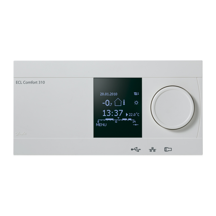
Danfoss ECL Comfort 310 Operating Manual
Application a333
Hide thumbs
Also See for ECL Comfort 310:
- Installation manual (167 pages) ,
- Operating manual (163 pages) ,
- Mounting manual (32 pages)
Table of Contents
Advertisement
Operating Guide
ECL Comfort 310, application A333
1.0 Table of Contents
1.0 Table of Contents ............................................... 1
1.1
Important safety and product information. . . . . . . . . . . . . . . . . . . . . 2
2.0 Installation ........................................................ 5
2.1
Before you start . . . . . . . . . . . . . . . . . . . . . . . . . . . . . . . . . . . . . . . . . . . . . . . . . . . . . 5
2.2
Identifying the system type . . . . . . . . . . . . . . . . . . . . . . . . . . . . . . . . . . . . . . 10
2.3
Mounting . . . . . . . . . . . . . . . . . . . . . . . . . . . . . . . . . . . . . . . . . . . . . . . . . . . . . . . . . . . 15
2.4
Placing the temperature sensors. . . . . . . . . . . . . . . . . . . . . . . . . . . . . . . . 18
2.5
Electrical connections. . . . . . . . . . . . . . . . . . . . . . . . . . . . . . . . . . . . . . . . . . . . . 20
2.6
Inserting the ECL Application Key . . . . . . . . . . . . . . . . . . . . . . . . . . . . . . 50
2.7
Check list . . . . . . . . . . . . . . . . . . . . . . . . . . . . . . . . . . . . . . . . . . . . . . . . . . . . . . . . . . . . 56
2.8
Navigation, ECL Application Key A333 . . . . . . . . . . . . . . . . . . . . . . . . . 57
3.0 Daily use ......................................................... 62
3.1
How to navigate . . . . . . . . . . . . . . . . . . . . . . . . . . . . . . . . . . . . . . . . . . . . . . . . . . . 62
3.2
Understanding the controller display . . . . . . . . . . . . . . . . . . . . . . . . . . 63
3.3
A general overview: What do the symbols mean? . . . . . . . . . . . 65
3.4
Monitoring temperatures and system
components . . . . . . . . . . . . . . . . . . . . . . . . . . . . . . . . . . . . . . . . . . . . . . . . . . . . . . . . 66
3.5
Influence overview . . . . . . . . . . . . . . . . . . . . . . . . . . . . . . . . . . . . . . . . . . . . . . . . 67
3.6
Manual control . . . . . . . . . . . . . . . . . . . . . . . . . . . . . . . . . . . . . . . . . . . . . . . . . . . . . 68
3.7
Schedule . . . . . . . . . . . . . . . . . . . . . . . . . . . . . . . . . . . . . . . . . . . . . . . . . . . . . . . . . . . . 69
4.0 Settings overview ............................................ 70
5.0 Settings........................................................... 73
5.1
Introduction to Settings . . . . . . . . . . . . . . . . . . . . . . . . . . . . . . . . . . . . . . . . . . 73
5.2
Flow temperature. . . . . . . . . . . . . . . . . . . . . . . . . . . . . . . . . . . . . . . . . . . . . . . . . . 74
5.3
Return limit . . . . . . . . . . . . . . . . . . . . . . . . . . . . . . . . . . . . . . . . . . . . . . . . . . . . . . . . . 76
5.4
Flow / power limit . . . . . . . . . . . . . . . . . . . . . . . . . . . . . . . . . . . . . . . . . . . . . . . . . 79
5.5
Optimization. . . . . . . . . . . . . . . . . . . . . . . . . . . . . . . . . . . . . . . . . . . . . . . . . . . . . . . . 82
5.6
Control parameters 1. . . . . . . . . . . . . . . . . . . . . . . . . . . . . . . . . . . . . . . . . . . . . . 87
5.7
Control parameters, refill pump(s) . . . . . . . . . . . . . . . . . . . . . . . . . . . . . . 92
5.8
Control parameters, circulation pump(s) . . . . . . . . . . . . . . . . . . . . . . 97
5.9
Pump control . . . . . . . . . . . . . . . . . . . . . . . . . . . . . . . . . . . . . . . . . . . . . . . . . . . . . 100
5.10 Refill water . . . . . . . . . . . . . . . . . . . . . . . . . . . . . . . . . . . . . . . . . . . . . . . . . . . . . . . . 103
5.11 Refill tank. . . . . . . . . . . . . . . . . . . . . . . . . . . . . . . . . . . . . . . . . . . . . . . . . . . . . . . . . . 110
5.12 Application . . . . . . . . . . . . . . . . . . . . . . . . . . . . . . . . . . . . . . . . . . . . . . . . . . . . . . . 113
5.13 Water meter . . . . . . . . . . . . . . . . . . . . . . . . . . . . . . . . . . . . . . . . . . . . . . . . . . . . . . 117
5.14 Flow meter . . . . . . . . . . . . . . . . . . . . . . . . . . . . . . . . . . . . . . . . . . . . . . . . . . . . . . . . 118
5.15 S7, S8, S9, S10 pressure . . . . . . . . . . . . . . . . . . . . . . . . . . . . . . . . . . . . . . . . . 121
5.16 Alarm . . . . . . . . . . . . . . . . . . . . . . . . . . . . . . . . . . . . . . . . . . . . . . . . . . . . . . . . . . . . . . 124
© Danfoss | 2017.09
6.0 Common controller settings............................ 129
6.1
Introduction to 'Common controller settings' . . . . . . . . . . . . . . 129
6.2
Time & Date. . . . . . . . . . . . . . . . . . . . . . . . . . . . . . . . . . . . . . . . . . . . . . . . . . . . . . . 130
6.3
Holiday . . . . . . . . . . . . . . . . . . . . . . . . . . . . . . . . . . . . . . . . . . . . . . . . . . . . . . . . . . . . 131
6.4
Input overview . . . . . . . . . . . . . . . . . . . . . . . . . . . . . . . . . . . . . . . . . . . . . . . . . . . 133
6.5
Log . . . . . . . . . . . . . . . . . . . . . . . . . . . . . . . . . . . . . . . . . . . . . . . . . . . . . . . . . . . . . . . . . 134
6.6
Output override. . . . . . . . . . . . . . . . . . . . . . . . . . . . . . . . . . . . . . . . . . . . . . . . . . 135
6.7
Key functions . . . . . . . . . . . . . . . . . . . . . . . . . . . . . . . . . . . . . . . . . . . . . . . . . . . . . 136
6.8
System . . . . . . . . . . . . . . . . . . . . . . . . . . . . . . . . . . . . . . . . . . . . . . . . . . . . . . . . . . . . . 138
7.0 Miscellaneous ................................................ 145
7.1
ECA 30 / 31 setup procedures . . . . . . . . . . . . . . . . . . . . . . . . . . . . . . . . . 145
7.2
Override function. . . . . . . . . . . . . . . . . . . . . . . . . . . . . . . . . . . . . . . . . . . . . . . . 153
7.3
Several controllers in the same system . . . . . . . . . . . . . . . . . . . . . . 156
7.4
Frequently asked questions. . . . . . . . . . . . . . . . . . . . . . . . . . . . . . . . . . . . 159
7.5
Definitions . . . . . . . . . . . . . . . . . . . . . . . . . . . . . . . . . . . . . . . . . . . . . . . . . . . . . . . . 162
7.6
Type (ID 6001), overview . . . . . . . . . . . . . . . . . . . . . . . . . . . . . . . . . . . . . . . 165
7.7
Parameter ID overview. . . . . . . . . . . . . . . . . . . . . . . . . . . . . . . . . . . . . . . . . . 166
VI.GU.T2.02 | 1
Advertisement
Table of Contents

Related Manuals for Danfoss ECL Comfort 310


Summary of Contents for Danfoss ECL Comfort 310
-
Page 1: Table Of Contents
Operating Guide ECL Comfort 310, application A333 1.0 Table of Contents 1.0 Table of Contents ..........1 6.0 Common controller settings......129 Important safety and product information..... 2 Introduction to ‘Common controller settings’... -
Page 2: Important Safety And Product Information
1.1.1 Important safety and product information This Installation Guide is associated with ECL Application Key A333 (order code no. 087H3818). The functions are realized in ECL Comfort 310 for advanced solutions, e.g. M-bus, Modbus and Ethernet (Internet) communication. The application A333 complies with ECL Comfort controllers 310 as of software version 1.11 (visible at start-up of the controller and in... - Page 3 Operating Guide ECL Comfort 310, application A333 Safety Note To avoid injury of persons and damages to the device, it is absolutely necessary to read and observe these instructions carefully. Necessary assembly, start-up, and maintenance work must be performed by qualified and authorized personnel only.
- Page 4 Operating Guide ECL Comfort 310, application A333 Parameters indicated with an ID no. like "1x607" mean a universal parameter. x stands for circuit / parameter group. Disposal Note This product should be dismantled and its components sorted, if possible, in various groups before recycling or disposal.
-
Page 5: Installation
Operating Guide ECL Comfort 310, application A333 2.0 Installation 2.1 Before you start The A333 application key contains 3 subtypes: A333.1, A333.2 Application A333.1: and A333.3 which are almost identical. Different and extra functions are described additionally. The application A333.1 is very flexible. - Page 6 Operating Guide ECL Comfort 310, application A333 If an acceptable pressure difference is not detected, the ECL controller activates the alarm and shifts the operating command to the opposite circulation pump. The heating can be switched OFF automatically when the outdoor temperature is higher than a selectable value.
- Page 7 Operating Guide ECL Comfort 310, application A333 The application A333.2 is very flexible and works like A333.1, Application A333.2: and with these additional features: * The circulation pumps P1 / P2 can, as an alternative to ON-OFF control, be speed controlled by means of a 0 - 10 volt signal.
- Page 8 Operating Guide ECL Comfort 310, application A333 The application A333.3 is very flexible and works like A333.2, Application A333.2: but with this feature: * The motorized control valve M1 is controlled by means of a 0 - 10 volt signal.
- Page 9 Operating Guide ECL Comfort 310, application A333 Application A333 in general: Up to two Remote Control Units, the ECA 30 can be connected to one ECL controller in order to control the ECL controller remotely. Exercise of circulation pumps and control valve in periods without heating demand can be arranged.
-
Page 10: Identifying The System Type
Operating Guide ECL Comfort 310, application A333 2.2 Identifying the system type Sketch your application The ECL Comfort controller series is designed for a wide range of heating, domestic hot-water (DHW) and cooling systems with different configurations and capacities. If your system differs from the diagrams shown here, you may want to make a sketch of the system about to be installed. - Page 11 Operating Guide ECL Comfort 310, application A333 A333.1, ex. a Heating system with control of up to 2 circulation pumps and up to 2 refill water pumps A333.1, ex. b Basic heating system VI.GU.T2.02 © Danfoss | 2017.09 | 11...
- Page 12 Operating Guide ECL Comfort 310, application A333 A333.1, ex. c Heating system with circulation pump feedback A333.1, ex. d Heating system with refill water system VI.GU.T2.02 12 | © Danfoss | 2017.09...
- Page 13 Operating Guide ECL Comfort 310, application A333 A333.1, ex. e Heating system with refill water and excess pressure system A333.2, ex. a Heating system with ON / OFF and speed control of up to 2 circulation pumps and up to 2 refill water pumps. Refill water storage control.
- Page 14 Operating Guide ECL Comfort 310, application A333 A333.3, ex. a Heating system with ON / OFF and speed control of up to 2 circulation pumps and up to 2 refill water pumps. Refill water storage control. Control valve M1 is controlled by 0 - 10 volt signal.
-
Page 15: Mounting
ECL Comfort 296 can be mounted • in a panel cut-out ECL Comfort 210 can be mounted in an ECL Comfort 310 base part (for future upgrade). Screws, PG cable glands and rawlplugs are not supplied. Locking the ECL Comfort 210 / 310 controller In order to fasten the ECL Comfort controller to its base part, secure the controller with the locking pin. - Page 16 Operating Guide ECL Comfort 310, application A333 The easy way to lock the controller to its base or unlock it is to use a screw driver as lever. Mounting on a wall Mount the base part on a wall with a smooth surface. Establish the electrical connections and position the controller in the base part.
- Page 17 Operating Guide ECL Comfort 310, application A333 Before removing the ECL Comfort controller from the base part, ensure that the supply voltage is disconnected. 2.3.2 Mounting the Remote Control Units ECA 30 / 31 Select one of the following methods: •...
-
Page 18: Placing The Temperature Sensors
Flow temperature sensor (ESMU, ESM-11 or ESMC) Place the sensor max. 15 cm from the mixing point. In systems with heat exchanger, Danfoss recommends that the ESMU-type to be inserted into the exchanger flow outlet. Make sure that the surface of the pipe is clean and even where the sensor is mounted. - Page 19 Operating Guide ECL Comfort 310, application A333 Pt 1000 temperature sensor (IEC 751B, 1000 Ω / 0 °C) Relationship between temperature and ohmic value: VI.GU.T2.02 © Danfoss | 2017.09 | 19...
-
Page 20: Electrical Connections
Operating Guide ECL Comfort 310, application A333 2.5 Electrical connections 2.5.1 Electrical connections 230 V a.c. The common ground terminal is used for connection of relevant ECL 210 / 310 components (pumps, motorized control valves). ECL 296 VI.GU.T2.02 20 | © Danfoss | 2017.09... - Page 21 Operating Guide ECL Comfort 310, application A333 2.5.2 Electrical connections, 230 V a.c., power supply, pumps, dampers, motorized control valves etc. Connections for A333.1 and A333.2, in general: See also the Mounting Guide (delivered with the application key) for application specific connections.
- Page 22 Operating Guide ECL Comfort 310, application A333 Wire cross section: 0.5 - 1.5 mm² Incorrect connection can damage the electronic outputs. Max. 2 x 1.5 mm² wires can be inserted into each screw terminal. VI.GU.T2.02 22 | © Danfoss | 2017.09...
- Page 23 Operating Guide ECL Comfort 310, application A333 2.5.3 Electrical connections, 230 V a.c., power supply, pumps, dampers, motorized control valves etc. Connections for A333.3, in general: See also the Mounting Guide (delivered with the application key) for application specific connections.
- Page 24 Operating Guide ECL Comfort 310, application A333 Wire cross section: 0.5 - 1.5 mm² Incorrect connection can damage the electronic outputs. Max. 2 x 1.5 mm² wires can be inserted into each screw terminal. VI.GU.T2.02 24 | © Danfoss | 2017.09...
- Page 25 Operating Guide ECL Comfort 310, application A333 2.5.4 Electrical connections ECA 32 Connections for A333.2 and A333.3, in general: See also the Mounting Guide (delivered with the application key) for application specific connections. Terminal Description Max. load Relay 10, not used 4 (2) A / 230 V a.c.*...
- Page 26 Operating Guide ECL Comfort 310, application A333 2.5.5 Electrical connections, ON / OFF valve V3 controlled from relay output in ECA 32 Connections for A333.2 and A333.3, in general: See also the Mounting Guide (delivered with the application key) for application specific connections.
- Page 27 Operating Guide ECL Comfort 310, application A333 2.5.7 Electrical connections, 230 V a.c., power supply, control of 2 or 3 phase powered pumps Connections for A333.1, in general: See also the Mounting Guide (delivered with the application key) for application specific connections.
- Page 28 Operating Guide ECL Comfort 310, application A333 2.5.9 Electrical connections, 230 V a.c., power supply, 0 - 10 volt for speed control of 1 phase powered pumps Connections for A333.2 and A333.3, in general: See also the Mounting Guide (delivered with the application key) for application specific connections.
- Page 29 Operating Guide ECL Comfort 310, application A333 2.5.11 Electrical connections, 230 V a.c., power supply, ON / OFF control and speed control (via Frequency Converter) of 1 phase powered pumps Connections for A333.2 and A333.3, in general: See also the Mounting Guide (delivered with the application key) for application specific connections.
- Page 30 Operating Guide ECL Comfort 310, application A333 2.5.13 Electrical connections, example with external Start / Stop control of a Frequency Converter for circulation pumps P1 / P2 Application A333.2 / A333.3 FC = Frequency Converter 2.5.14 Electrical connections, example with external Start / Stop control of a Frequency Converter for refill water pumps P3 / P4 Application A333.2 / A333.3...
- Page 31 Operating Guide ECL Comfort 310, application A333 2.5.15 Electrical connections, safety thermostats, 230 V a.c. or 24 V a.c. With safety thermostat, 1–step closing: Motorized control valve without safety function With safety thermostat, 1–step closing: Motorized control valve with safety function With safety thermostat, 2–step closing:...
- Page 32 Operating Guide ECL Comfort 310, application A333 When ST is activated by a high temperature, the safety circuit in the motorized control valve closes the valve immediately. When ST1 is activated by a high temperature (the TR temperature), the motorized control valve is closed gradually. At a higher temperature (the ST temperature), the safety circuit in the motorized control valve closes the valve immediately.
- Page 33 Operating Guide ECL Comfort 310, application A333 2.5.16 Electrical connections, 24 V a.c. (ECL 310 only), power supply, pumps, motorized valves etc. Connections for A333.1 and A333.2, in general: See also the Mounting Guide (delivered with the application key) for application specific connections.
- Page 34 Operating Guide ECL Comfort 310, application A333 Wire cross section: 0.5 - 1.5 mm² Incorrect connection can damage the electronic outputs. Max. 2 x 1.5 mm² wires can be inserted into each screw terminal. Do not connect 230 V a.c. powered components to a 24 V a.c. power supplied controller directly.
- Page 35 Operating Guide ECL Comfort 310, application A333 2.5.17 Electrical connections, 24 V a.c. (ECL 310 only), power supply, pumps, motorized valves etc. Connections for A333.3, in general: See also the Mounting Guide (delivered with the application key) for application specific connections.
- Page 36 Operating Guide ECL Comfort 310, application A333 Wire cross section: 0.5 - 1.5 mm² Incorrect connection can damage the electronic outputs. Max. 2 x 1.5 mm² wires can be inserted into each screw terminal. Do not connect 230 V a.c. powered components to a 24 V a.c. power supplied controller directly.
- Page 37 Operating Guide ECL Comfort 310, application A333 2.5.18 Electrical connections ECA 32 Connections for A333.2 and A333.3, in general: See also the Mounting Guide (delivered with the application key) for application specific connections. Terminal Description Max. load Relay 10, not used 4 (2) A / 24 V a.c.*...
- Page 38 See also the Mounting Guide (delivered with the application key) for application specific connections. Application A333.3 The transformer for supplying the actuator must be a double-isolated version. The ECL Comfort 310 and the actuator for the control valve M1 must have separate transformers. VI.GU.T2.02 38 | © Danfoss | 2017.09...
- Page 39 Operating Guide ECL Comfort 310, application A333 2.5.21 Electrical connections, 24 V a.c., power supply, control of 2 or 3 phase powered pumps Connections for A333.1, in general: See also the Mounting Guide (delivered with the application key) for application specific connections.
- Page 40 Operating Guide ECL Comfort 310, application A333 2.5.23 Electrical connections, 24 V a.c., power supply, ON / OFF control and speed control (via Frequency Converter) of 1, 2 or 3 phase powered pumps Connections for A333.2 and A333.3, in general: See also the Mounting Guide (delivered with the application key) for application specific connections.
- Page 41 Operating Guide ECL Comfort 310, application A333 2.5.24 Electrical connections, Pt 1000 temperature sensors and signals Connections for A333, in general: See also the Mounting Guide (delivered with the application key) for application specific connections. Type Terminal Sensor / description (recomm.)
- Page 42 Operating Guide ECL Comfort 310, application A333 2.5.25 Electrical connections, pressure transmitters, 0 - 10 volt types S7, S8, S9, S10 2.5.26 Electrical connections, pressure transmitters, 4 - 20 mA types S7, S8, S9, S10 4 - 20 mA through a resistor of 500 ohm gives a voltage of 2 - 10 volt.
- Page 43 Operating Guide ECL Comfort 310, application A333 2.5.27 Electrical connections ECA 32 Connections for A333.2 and A333.3, in general: See also the Mounting Guide (delivered with the application key) for application specific connections. Terminal Sensor / description 50 and 49 S11 Position signal from M1, 0 - 10 volt...
- Page 44 Operating Guide ECL Comfort 310, application A333 2.5.28 Electrical connections, ECA 32, flow meters, pulse types A333.2 / A333.3 F1 and F2, pulse input 2.5.29 Electrical connections, ECA 32, flow meter, 0 - 10 volt type A333.2 / A333.3 F2 to input S13 (0 - 10 volt input) VI.GU.T2.02...
- Page 45 Operating Guide ECL Comfort 310, application A333 2.5.30 Electrical connections, ECA 32, pressure transmitter, 0 - 10 volt type A333.2 / A333.3 S12, level in refill water storage tank 2.5.31 Electrical connections, ECA 32, pressure transmitter, 4 - 20 mA type A333.2 / A333.3...
- Page 46 ECA 30 / 31 to each circuit. The electrical connections are done in parallel. Max. 2 ECA 30 / 31 can be connected to an ECL Comfort 310 controller or to ECL Comfort 210 / 296 / 310 controllers in a master-slave system.
- Page 47 Operating Guide ECL Comfort 310, application A333 ECA information message: ‘Application req. newer ECA’: The software (firmware) of your ECA does not comply with the software (firmware) of your ECL Comfort controller. Please contact your Danfoss sales office. Some applications do not contain functions related to actual room temperature.
- Page 48 Operating Guide ECL Comfort 310, application A333 2.5.34 Electrical connections, master / slave systems The controller can be used as master or slave in master / slave systems via the internal ECL 485 communication bus (2 x twisted pair cable).
- Page 49 Operating Guide ECL Comfort 310, application A333 2.5.35 Electrical connections, communication Electrical connections, Modbus Electrical connections, M-bus Example, M-bus connections VI.GU.T2.02 © Danfoss | 2017.09 | 49...
-
Page 50: Inserting The Ecl Application Key
Operating Guide ECL Comfort 310, application A333 2.6 Inserting the ECL Application Key 2.6.1 Inserting the ECL Application Key The ECL Application Key contains ECL Comfort 210 / 310 • the application and its subtypes, • currently available languages, •... - Page 51 Operating Guide ECL Comfort 310, application A333 Automatic update of controller software (firmware): The software of the controller is updated automatically when the key is inserted (as of controller version 1.11 (ECL 210 / 310) and version 1.58 (ECL 296)). The following animation will be shown when the...
- Page 52 Operating Guide ECL Comfort 310, application A333 Application Key: Situation 1 The controller is new from the factory, the ECL Application Key is not inserted. An animation for the ECL Application Key insertion is displayed. Insert the Application Key .
- Page 53 Operating Guide ECL Comfort 310, application A333 Application Key: Situation 2 The controller already runs an application. The ECL Application Key is inserted, but the application needs to be changed. To change to another application on the ECL Application Key, the current application in the controller must be erased (deleted).
- Page 54 Operating Guide ECL Comfort 310, application A333 Application Key: Situation 3 A copy of the controllers settings is needed for configuring another controller. This function is used • for saving (backup) of special user and system settings • when another ECL Comfort controller of the same type (210, 296 or 310) must be configured with the same application but user / system settings differ from the factory settings.
- Page 55 Operating Guide ECL Comfort 310, application A333 2.6.2 ECL Application Key, copying data General principles When the controller is connected and operating, you can check and adjust all or some of the basic settings. The new settings can be stored on the Key.
-
Page 56: Check List
Operating Guide ECL Comfort 310, application A333 2.7 Check list Is the ECL Comfort controller ready for use? Make sure that the correct power supply is connected to terminals 9 and 10 (230 V or 24 V). Make sure the correct phase conditions are connected:... -
Page 57: Navigation, Ecl Application Key A333
Operating Guide ECL Comfort 310, application A333 2.8 Navigation, ECL Application Key A333 Parameter list, application A333, Heating Sub-menu A333 Home MENU ID nos. A333.1 A333.2 A333.3 Heating Function Schedule Schedule Settings Flow Heat curve temperature 11178 Temp. max. 11179 Temp. - Page 58 Operating Guide ECL Comfort 310, application A333 Parameter list, application A333, Heating, continued Sub-menu A333 Home MENU Heating ID nos. Function A333.1 A333.2 A333.3 Settings 11321 Pressure, des. Control par., P refill 13184 13185 13187 13197 13165 V.out, max. 13167 V.out, min.
- Page 59 Operating Guide ECL Comfort 310, application A333 Parameter list, application A333, Heating, continued Sub-menu A333 Home MENU Heating ID nos. Function A333.1 A333.2 A333.3 Settings Level Refill tank 16113 Filter constant 16607 Low X 16608 High X 16602 Level, desired...
- Page 60 Operating Guide ECL Comfort 310, application A333 Parameter list, application A333, Heating, continued Sub-menu A333 Home MENU Heating ID nos. Function A333.1 A333.2 A333.3 Holiday Holiday Alarm Temp. monitor 11147 Upper diff 11148 Lower diff 11149 Delay 11150 Lowest temp.
- Page 61 Operating Guide ECL Comfort 310, application A333 Parameter list, application A333, Common controller Sub-menu A333 Home MENU Common controller ID nos. Function A333.1 A333.2 A333.3 Time & date Input overview Output override Key functions New application Application Factory setting Copy...
-
Page 62: Daily Use
Operating Guide ECL Comfort 310, application A333 3.0 Daily use 3.1 How to navigate You navigate in the controller by turning the dial left or right to the desired position ( The dial has a built-in accellerator. The faster you turn the dial, the faster it reaches the limits of any wide setting range. -
Page 63: Understanding The Controller Display
Operating Guide ECL Comfort 310, application A333 3.2 Understanding the controller display This section describes the function in general for the ECL Comfort 210 / 296 / 310 series. The shown displays are typical and not application related. They might differ from the displays in your application. - Page 64 Operating Guide ECL Comfort 310, application A333 If the temperature value is displayed as "- -" the sensor in question is not connected. "- - -" the sensor connection is short-circuited. Setting the desired temperature Depending on the chosen circuit and mode, it is possible to enter all daily settings directly from the overview displays (see also the next page concerning symbols).
-
Page 65: A General Overview: What Do The Symbols Mean
Operating Guide ECL Comfort 310, application A333 3.3 A general overview: What do the symbols mean? Symbol Description Symbol Description Alarm Outdoor temp. Letter Relative humidity indoor Temperature Event Room temp. Monitoring temperature sensor connection DHW temp. Display selector Position indicator Max. - Page 66 Operating Guide ECL Comfort 310, application A333 3.4 Monitoring temperatures and system components This section describes the function in general for the ECL Comfort 210 / 296 / 310 series. The shown displays are typical and not application related. They might differ from the displays in your application.
-
Page 67: Influence Overview
Operating Guide ECL Comfort 310, application A333 3.5 Influence overview This section describes the function in general for the ECL Comfort 210 / 296 / 310 series. The shown displays are typical and not application related. They might differ from the displays in your application. -
Page 68: Manual Control
Operating Guide ECL Comfort 310, application A333 3.6 Manual control This section describes the function in general for the ECL Comfort 210 / 296 / 310 series. The shown displays are typical and not application related. They might differ from the displays in your application. -
Page 69: Schedule
Operating Guide ECL Comfort 310, application A333 3.7 Schedule 3.7.1 Set your schedule This section describes the schedule in general for the ECL Comfort 210 / 296 / 310 series. The shown displays are typical and not application related. They might differ from the displays in your application. -
Page 70: Settings Overview
Operating Guide ECL Comfort 310, application A333 4.0 Settings overview For factory settings and setting range, see appendix “Parameter ID overview”. Parameters indicated with an ID no. like "1x607" mean a universal parameter. x stands for circuit / parameter group. - Page 71 Operating Guide ECL Comfort 310, application A333 Page Setting Factory settings in circuit(s) 13187 Nz (neutral zone) (A333.2 / A333.3) 13197 Td (Time derivative) (A333.2 / A333.3) 13322 Pressure diff. 15615 Alarm low 15617 Alarm time-out 16113 Filter constant 16194 Stop difference (A333.2 / A333.3)
- Page 72 Operating Guide ECL Comfort 310, application A333 Page Setting Factory settings in circuit(s) 1x113 Filter constant 1x113 Filter constant (S7, S8, S9, S10) Units 1x115 High limit Y2 (flow / power limitation, high limit, Y-axis) 1x116 1x117 Low limit Y1 (flow / power limitation, low limit, Y-axis)
-
Page 73: Settings
Operating Guide ECL Comfort 310, application A333 5.0 Settings 5.1 Introduction to Settings Descriptions of settings (parameter's functions) are divided into groups as used in the ECL Comfort 210 / 296 / 310 controller's menu structure. Examples: "Flow temperature", "Room limit" and so on. -
Page 74: Flow Temperature
Operating Guide ECL Comfort 310, application A333 5.2 Flow temperature The ECL Comfort controller determines and controls the flow temperature related to the outdoor temperature. This relationship Desired flow temperature is called the heat curve. The heat curve is set by means of 6 coordinate points. The desired flow temperature is set at 6 pre-defined outdoor temperature values. - Page 75 Operating Guide ECL Comfort 310, application A333 Choosing a heat curve slope The heat curves represent the desired flow temperature at different outdoor temperatures and at a desired room temperature of 20 °C. The small arrows ( ) indicate 6 different outdoor temperature values at which you can change the heat curve.
-
Page 76: Return Limit
Operating Guide ECL Comfort 310, application A333 5.3 Return limit The return temperature limitation is based on the outdoor Return temperature limitation temperature. Typically in district heating systems a higher return temperature is accepted at a decrease in outdoor temperature. The relationship between the return temperature limits and outdoor temperature is set in two coordinates. - Page 77 Operating Guide ECL Comfort 310, application A333 MENU > Settings > Return limit 1x034 High limit Y2 (return temp. limitation, high limit, Y-axis) Set the return temperature limitation referring to the outdoor temperature value set in 'Low T out X2' .
- Page 78 Operating Guide ECL Comfort 310, application A333 MENU > Settings > Return limit Example The return limit is active below 50 °C. Infl. - min. (return temp. limitation - min. influence) 1x036 The influence is set to -3.0. The actual return temperature is 2 degrees too low.
-
Page 79: Flow / Power Limit
Operating Guide ECL Comfort 310, application A333 5.4 Flow / power limit A flow or energy meter can be connected (M-bus signal) to the ECL Flow / power limitation controller in order to limit the flow or consumed power. The flow / power limitation can be based on the outdoor temperature. - Page 80 Operating Guide ECL Comfort 310, application A333 MENU > Settings > Flow / power limit 1x119 High T out X1 (flow / power limitation, high limit, X-axis) Set the outdoor temperature value for the low flow / power limitation. See Appendix “Parameter ID overview”...
- Page 81 Input type 11109 Choice of M-bus signal from energy meter number 1 ... 5. Only possible in ECL Comfort 310. Flow or power limitation is based on M-bus signal (ECL Comfort 310 controllers only). OFF: No M-bus signal acquired. EM1 ... EM5: Energy meter number.
-
Page 82: Optimization
Operating Guide ECL Comfort 310, application A333 5.5 Optimization MENU > Settings > Optimization Auto saving (saving temp. dependent on outdoor temp.) 1x011 Below the set value for the outdoor temperature, the saving temperature setting has no influence. Above the set value for the outdoor temperature, the saving temperature relates to the actual outdoor temperature. - Page 83 Operating Guide ECL Comfort 310, application A333 MENU > Settings > Optimization Boost 1x012 Shortens the heating-up period by increasing the desired flow temperature by the percentage you set. See Appendix “Parameter ID overview” OFF: The boost function is not active.
- Page 84 Operating Guide ECL Comfort 310, application A333 MENU > Settings > Optimization Table I: 1x014 Optimizer (optimizing time constant) System type Left digit Heat accumulation of the Optimizes the start and stop times for the comfort temperature period to building obtain the best comfort at the lowest energy consumption.
- Page 85 Operating Guide ECL Comfort 310, application A333 MENU > Settings > Optimization Example: Optimization of Comfort from 07:00 - 22:00 1x026 Pre-stop (optimized stop time) Disable the optimized stop time. See Appendix “Parameter ID overview” OFF: The optimized stop time is disabled.
- Page 86 Operating Guide ECL Comfort 310, application A333 MENU > Settings > Optimization Summer, cut-out 1x179 Summer, cut-out (limit for heating cut-out) See Appendix “Parameter ID overview” The heating can be switched OFF when the outdoor temperature is higher than the set value. The valve closes and after the post-run time, the heating circulation pump stops.
-
Page 87: Control Parameters 1
Operating Guide ECL Comfort 310, application A333 5.6 Control parameters 1 The applications A333.1 and A333.2 control the motorized control valve M1 by means of 3-point control. The application A333.3 controls the M1 by means of a 0 - 10 volt control signal. - Page 88 Operating Guide ECL Comfort 310, application A333 MENU > Settings > Control parameters 1 Position (A333.2 / A333.3) Read-out Circuit Setting range Factory setting Position of the motorized control valve M1 is indicated as a % value. A 0 - 10 volt signal comes from a position measuring in M1 and is applied to input S11 (ECA 32).
- Page 89 Operating Guide ECL Comfort 310, application A333 MENU > Settings > Control parameters 1 Low X 1x607 Definition of which voltage value corresponds to which position value. The voltage (as a 0 - 10 volt signal) comes from a position measuring in M1 and is applied to input S11 (ECA 32).
- Page 90 Operating Guide ECL Comfort 310, application A333 MENU > Settings > Control parameters 1 11174 Motor pr. (motor protection) — only A333.1, A333.2 Circuit Setting range Factory setting Recommended for heating systems with variable load. OFF / 10 ... 59 m Prevents the controller from unstable temperature control (and resulting actuator oscillations).
- Page 91 Operating Guide ECL Comfort 310, application A333 MENU > Settings > Control parameters 1 Nz (neutral zone) 11187 Circuit Setting range Factory setting The neutral zone is symmetrical around the desired flow temperature 1 ... 9 K value, i.e. half the value is above and half the value is below this temperature.
-
Page 92: Control Parameters, Refill Pump(S)
Operating Guide ECL Comfort 310, application A333 5.7 Control parameters, refill pump(s) Control parameters for refill water pump(s), applications A333.2 / A333.3 The refill water pumps P3 / P4 can be speed controlled by means of a 0 - 10 volt signal. The speed control signal comes from the output M2 (terminals 60 and 56) on the ECA 32 module. - Page 93 Operating Guide ECL Comfort 310, application A333 MENU > Settings > Control parameters, refill pump(s) Pressure des. (A333.2 / A333.3) 11321 Circuit Setting range Factory setting 0.2 . . . 25.0 bar 3.0 bar Setting of desired pressure at S10 in order to speed control the refill pump(s) P3 / P4.
- Page 94 Operating Guide ECL Comfort 310, application A333 MENU > Settings > Control parameters, refill pump(s) Tn (integration time ) (A333.2 / A333.3) 13185 Circuit Setting range Factory setting 1 . . . 999 sec 25 sec Set the integration time for the control of the pressure at S10.
- Page 95 Operating Guide ECL Comfort 310, application A333 MENU > Settings > Control parameters, refill pump(s) Example: V out min. (A333.2 / A333.3) 13167 Circuit Setting range Factory setting A setting of 15 % means that the output voltage will be 1.5 volt as a minimum.
- Page 96 Operating Guide ECL Comfort 310, application A333 MENU > Settings > Control parameters, refill pump(s) Wake up level (A333.2 / A333.3) 11330 Circuit Setting range Factory setting 0 . . . 100 % 40 % After elapse of the "Sleep mode" time and a continued refill demand, the refill water pump restarts with a speed level as the set value.
-
Page 97: Control Parameters, Circulation Pump(S)
Operating Guide ECL Comfort 310, application A333 5.8 Control parameters, circulation pump(s) Control parameters for circulation pump(s), applications A333.2 / A333.3 The circulation pumps P1 / P2 can be speed controlled by means of a 0 - 10 volt signal. The speed control signal comes from the output M3 (terminals 61 and 56) on the ECA 32 module. - Page 98 Operating Guide ECL Comfort 310, application A333 MENU > Settings > Control parameters, circulation pump(s) Xp (proportional band) 1x184 See Appendix “Parameter ID overview” Set the proportional band. A higher value will result in a stable but slow control of the flow temperature.
- Page 99 Operating Guide ECL Comfort 310, application A333 MENU > Settings > Control parameters, circulation pump(s) Example: V out max. (A333.2 / A333.3) 12165 Circuit Setting range Factory setting A setting of 60 % means that the output voltage will be 6 volt as a maximum.
-
Page 100: Pump Control
Operating Guide ECL Comfort 310, application A333 5.9 Pump control The A333 application can operate with one or two circulation pumps, P1 or P1 / P2. When operating with two circulation pumps, the pumps are controlled alternately, according to a time set-up. - Page 101 Operating Guide ECL Comfort 310, application A333 MENU > Settings > Pump control Retry time 11310 Circuit Setting range Factory setting OFF / 1... 99 m If an alarm has been generated for the pump or alarms have been generated for both pumps, this setting will determine the time between the time of the alarm and the retry time for repeated pump start.
- Page 102 Operating Guide ECL Comfort 310, application A333 MENU > Settings > Pump control Change time 11312 Circuit Setting range Factory setting 0 ... 23 The exact time of the day, where the shift must take place. The day is divided into 24 hours.
-
Page 103: Refill Water
Operating Guide ECL Comfort 310, application A333 5.10 Refill water Leaks on the consumers side (secondary side) will result in falling static pressure and thereby a poor supply of heating. A refill water function can inject water to increase the static pressure. - Page 104 Operating Guide ECL Comfort 310, application A333 MENU > Settings > Refill water Change duration 12311 Circuit Setting range Factory setting OFF / 1 . . . 60 days 7 days The number of days between refill water pump change-over.
- Page 105 Operating Guide ECL Comfort 310, application A333 MENU > Settings > Refill water 13322 Pressure diff. Circuit Setting range Factory setting 0.1 . . . 5.0 bar 1.5 bar Setting of the switching difference for the measured pressure at S10.
- Page 106 Operating Guide ECL Comfort 310, application A333 MENU > Settings > Refill water 11319 Max. pressure diff. Circuit Setting range Factory setting -5.0 . . . -0.1 bar -0.5 bar Setting of the pressure difference below "Max. pressure" to ensure an acceptable pressure in the heating system.
- Page 107 Operating Guide ECL Comfort 310, application A333 MENU > Settings > Refill water Time-out 11323 Circuit Setting range Factory setting 1 . . . 1000 sec 100 sec Setting of the max. time for refill. The pressure, measured by S10, must be OK within the set time.
- Page 108 Operating Guide ECL Comfort 310, application A333 MENU > Settings > Refill water P exercise (pump exercise) 11022 Circuit Setting range Factory setting OFF / 1 ... 200 s The time the pump is activated during exercise. Exercise takes place every day (at 12:00).
- Page 109 Operating Guide ECL Comfort 310, application A333 MENU > Settings > Refill water Alarm handling 12316 Circuit Setting range Factory setting OFF / ON Choose whether the controller must react on an unacceptable pressure at S10. OFF: Alarm function is disabled. Refill water pump is not stopped although the pressure is too low.
-
Page 110: Refill Tank
Operating Guide ECL Comfort 310, application A333 5.11 Refill tank A refill water storage tank can be controlled. The water level at S12 is measured by means of a pressure transmitter (giving a 0 - 10 volt signal in relation to the measured pressure). - Page 111 Operating Guide ECL Comfort 310, application A333 MENU > Settings > Refill tank Filter constant 16113 Circuit Setting range Factory setting 1 - 250 The filter constant dampens the water level signal from the pressure transmitter in order to make a stable read-out and related functions.
- Page 112 Operating Guide ECL Comfort 310, application A333 MENU > Settings > Refill tank Level, desired (A333.2 / A333.3) 16602 Circuit Setting range Factory setting 0.2 . . . 25.0 m 3.0 m Setting of desired water level (measured by S12) in the refill water storage tank.
-
Page 113: Application
Operating Guide ECL Comfort 310, application A333 5.12 Application MENU > Settings > Application Temp. Setting in ‘Demand offset’ 1x017 Demand offset The desired flow temperature in heating circuit 1 can be influenced by the demand for a desired flow temperature from another controller (slave) or Des. - Page 114 Operating Guide ECL Comfort 310, application A333 MENU > Settings > Application 1x052 DHW priority (closed valve / normal operation) The heating circuit can be closed when the controller acts as slave and when This setting must be considered if this controller is a slave.
- Page 115 Operating Guide ECL Comfort 310, application A333 MENU > Settings > Application Frost pr. T (frost protection temp.) 1x093 The frost protection temperature can also be set in your favorite Set the desired flow temperature at temperature sensor S3 to protect the display when the mode selector is in frost protection mode.
- Page 116 Operating Guide ECL Comfort 310, application A333 MENU > Settings > Application Ext. mode (external override mode) 11142 Circuit Setting range Factory setting See also ‘Ext. input’ . COMFORT / SAVING COMFORT Choose external override mode. The mode override can be activated for saving or comfort mode.
-
Page 117: Water Meter
Operating Guide ECL Comfort 310, application A333 5.13 Water meter Applications A333.2 / A333.3 A water meter, F1, can measure the amount of refill water injected into the heating installation. The water flow at F1 is measured by means of: a flow meter, giving pulses to "Pulse 1"... -
Page 118: Flow Meter
Operating Guide ECL Comfort 310, application A333 5.14 Flow meter Applications A333.2 / A333.3 A flow meter, F2, can measure the circulating water flow in the heating installation. The flow at F2 is measured by means of: a flow meter, giving a 0 - 10 volt signal and applied to S13 on the ECA 32 module or a flow meter, giving pulses and applied to "Pulse 2"... - Page 119 Operating Guide ECL Comfort 310, application A333 MENU > Settings > Flow meter Low X (A333.2 / A333.3) 17607 Circuit Setting range Factory setting 0.0 . . . 10.0 V 2.0 V Definition of which voltage value corresponds to which water flow value.
- Page 120 Operating Guide ECL Comfort 310, application A333 MENU > Settings > Flow meter 17114 Pulse (A333.2 / A333.3) Circuit Setting range Factory setting OFF / 1 . . . 9999 l Choice of flow meter type. Setting of the value of each pulse from the flow meter. This parameter is used when the flow meter is connected to the "Pulse 2"...
-
Page 121: S7, S8, S9, S10 Pressure
Operating Guide ECL Comfort 310, application A333 5.15 S7, S8, S9, S10 pressure Pressure measuring The pressures at S7, S8, S9 and S10 are measured by means of pressure transmitters, all giving a 0 - 10 volt signal in relation to the measured pressure. - Page 122 Operating Guide ECL Comfort 310, application A333 MENU > Settings > S7, S8, S9, S10 pressure Pressure (S7, S8, S9, S10) Read-out Circuit Setting range Factory setting The pressure is indicated as a value measured in bar. A 0 - 10 volt signal comes directly from a pressure transmitter (voltage output) or converted by means of a resistor from a pressure transmitter (current output).
- Page 123 Operating Guide ECL Comfort 310, application A333 MENU > Settings > S7, S8, S9, S10 pressure 1x607 Low X (S7, S8, S9, S10) Factory setting Circuit Setting range 0.0 . . . 10.0 V 2.0 V Definition of which voltage value corresponds to which pressure value.
-
Page 124: Alarm
Operating Guide ECL Comfort 310, application A333 5.16 Alarm The alarm function activates A1 (relay 6). The alarm relay can activate a lamp, a horn, an input to an alarm transmitting device etc. The alarm relay is activated • as long as the alarm reason is present (automatic reset) or •... -
Page 125: Danfoss | 2017.09
Operating Guide ECL Comfort 310, application A333 MENU > Settings > Alarm Lower difference 1x148 Lower difference The alarm is activated if the actual flow / duct temperature decreases more than the set difference (acceptable temperature difference below the desired flow / duct temperature). -
Page 126: Danfoss | 2017.09
Operating Guide ECL Comfort 310, application A333 MENU > Settings > Alarm Alarm high (A333.2 / A333.3) 16614 Circuit Setting range Factory setting When the "Alarm high" or "Alarm Low" alarm is activated: 0.0 . . . 25.0 m 25.0 m... -
Page 127: Danfoss | 2017.09
Operating Guide ECL Comfort 310, application A333 MENU > Settings > Alarm Alarm time-out (A333.2 / A333.3) 16617 Circuit Setting range Factory setting 0 . . . 250 s 15 s If an alarm condition from either 'Alarm high' or 'Alarm low' is present for a longer time than the set Alarm time-out (in seconds), the alarm function is activated. -
Page 128: Danfoss | 2017.09
Operating Guide ECL Comfort 310, application A333 MENU > Settings > Alarm Alarm time-out 1x617 Circuit Setting range Factory setting 0 . . . 100 m 10 m If an alarm condition from either 'Alarm high' or 'Alarm low' is present for a longer time than the set Alarm time-out (in minutes), the alarm function is activated. -
Page 129: Common Controller Settings
Operating Guide ECL Comfort 310, application A333 6.0 Common controller settings 6.1 Introduction to ‘Common controller settings’ Some general settings which apply to the entire controller are Circuit selector located in a specific part of the controller. To enter ‘Common controller settings’:... -
Page 130: Time & Date
Operating Guide ECL Comfort 310, application A333 6.2 Time & Date It is only necessary to set the correct date and time in connection with the first use of the ECL Comfort controller or after a power break of more than 72 hours. -
Page 131: Holiday
Operating Guide ECL Comfort 310, application A333 6.3 Holiday This section describes the function in general for the ECL Comfort 210 / 296 / 310 series. The shown displays are typical and not application related. They might differ from the displays in your application. - Page 132 Operating Guide ECL Comfort 310, application A333 Holiday, specific circuit / Common Controller Example 1: When setting one holiday program in specific circuit and another Circuit 1: holiday program in Common Controller, a priority will be taken Holiday set to "Saving"...
-
Page 133: Input Overview
Operating Guide ECL Comfort 310, application A333 6.4 Input overview This section describes the function in general for the ECL Comfort 210 / 296 / 310 series. The shown displays are typical and not application related. They might differ from the displays in your application. -
Page 134: Log
Operating Guide ECL Comfort 310, application A333 6.5 Log This section describes the function in general for the ECL Comfort 210 / 296 / 310 series. The shown displays are typical and not application related. They might differ from the displays in your application. -
Page 135: Output Override
Operating Guide ECL Comfort 310, application A333 6.6 Output override This section describes the function in general for the ECL Comfort 210 / 296 / 310 series. The shown displays are typical and not application related. They might differ from the displays in your application. -
Page 136: Key Functions
Operating Guide ECL Comfort 310, application A333 6.7 Key functions New application Erase application: Removes the existing application. As soon as the ECL key is inserted, another application can be chosen. Application Gives an overview over the actual application in the ECL controller. Push the dial again to exit the overview. - Page 137 Operating Guide ECL Comfort 310, application A333 The “Key overview” does not inform — through ECA 30 / 31 — about the subtypes of the application key. Key inserted / not inserted, description: ECL Comfort 210 / 310, controller versions lower than 1.36: Take out the application key;...
-
Page 138: System
Operating Guide ECL Comfort 310, application A333 6.8 System 6.8.1 ECL version In ‘ECL version’ you will always be able to find an overview of the Example, ECL version data related to your electronic controller. Please have this information available if you need to contact your Danfoss sales organization concerning the controller. - Page 139 See MENU > Common controller > System > M-bus config. Technical info: • The M-bus data are based on standard EN-1434. • Danfoss recommends AC supplied energy meters in order to avoid battery draining. MENU > Common controller > System > M-bus config. State Read-out...
- Page 140 Operating Guide ECL Comfort 310, application A333 MENU > Common controller > System > M-bus config. Command 5998 Scan time can take up to 12 minutes. Circuit Setting range Factory setting When all energy meters are found, the command can be changed to INIT or NONE.
- Page 141 Operating Guide ECL Comfort 310, application A333 MENU > Common controller > System > M-bus config. Scan time 6002 Energy meter 1 (2, 3, 4, 5) If the energy meter is battery powered, the scan time should be set to a high value to prevent a too fast battery draining.
- Page 142 Operating Guide ECL Comfort 310, application A333 6.8.8 Sensor offset (new functionality as from firmware 1.59) The measured temperature can be offset adjusted in order to compensate for cable resistance or a not-optimum place for the temperature sensor. The adjusted temperature can be seen in "Raw input overview"...
- Page 143 Operating Guide ECL Comfort 310, application A333 2048 ECL 485 addr. (master / slave address) Factory setting Circuit Setting range The total cable length of max. 200 m (all devices incl. the internal ECL 0 ... 15 485 communication bus) should not be exceeded.
- Page 144 Operating Guide ECL Comfort 310, application A333 6.8.11 Language Language 2050 Circuit Setting range Factory setting Local language is selected during installation. If you want to change to English / ‘Local’ English another local language, the application must be reinstalled. However, it is always possible to change between the local language and English.
-
Page 145: Miscellaneous
Operating Guide ECL Comfort 310, application A333 7.0 Miscellaneous 7.1 ECA 30 / 31 setup procedures ECA 30 (code no. 087H3200) is a remote control unit with built-in room temperature sensor. ECA 31 (code no. 087H3201) is a remote control unit with built-in room temperature sensor and humidity sensor (relative humidity). - Page 146 Operating Guide ECL Comfort 310, application A333 The ECL menus are as described for the ECL controller. Most of the settings done directly in the ECL controller can be done via the ECA 30 / 31 too. All settings can be seen even if the application key is not inserted in the ECL controller.
- Page 147 Operating Guide ECL Comfort 310, application A333 When ECA 30 / 31 is in ECA MENU mode, the date and measured room temperature is displayed. ECA MENU > ECA settings > ECA sensor Room T Offset Example: Setting range Factory setting Room T offset: 0.0 K...
- Page 148 Operating Guide ECL Comfort 310, application A333 ECA MENU > ECA system > ECA display Contrast (display contrast) Setting range Factory setting 0 ... 10 Adjust the contrast of the display. Low contrast. High contrast. ECA MENU > ECA system > ECA display...
- Page 149 Operating Guide ECL Comfort 310, application A333 ECA MENU > ECA system > ECA communication Connection addr. (Connection address) Setting range Factory setting 1 … 9 / 15 An ECA 30 / 31 can in an ECL 485 bus system (master – slave) be set to communicate, one by one, with all addressed ECL controllers.
- Page 150 Operating Guide ECL Comfort 310, application A333 ECA MENU > ECA system > ECA override Override circuit Setting range Factory setting OFF / 1 … 4 The circuit in question for override in the ECL controller must be in scheduled mode.
- Page 151 Operating Guide ECL Comfort 310, application A333 ECA MENU > ECA factory > ECA clear apps. Erase all apps. (Erase all applications) Erase all applications which are in the ECA 30 / 31. After erasing, the application can be uploaded again.
- Page 152 Operating Guide ECL Comfort 310, application A333 ECA MENU > ECA factory > Reset ECL addr. Reset ECL addr. (Reset ECL address) If none of the connected ECL Comfort controllers has the address 15, the ECA 30 / 31 can set all connected ECL controllers on the ECL 485 bus back to address 15.
-
Page 153: Override Function
Operating Guide ECL Comfort 310, application A333 7.2 Override function Example, override switch connected to S8: The ECL 210 / 296 / 310 controllers can receive a signal in order to override the existing schedule. The override signal can be a switch or a relay contact. - Page 154 Operating Guide ECL Comfort 310, application A333 Example 1 ECL in Saving mode, but in Comfort mode at override. Choose an unused input, for example S8. Connect the override switch or override relay contact. Settings in ECL: 1. Select circuit > MENU > Settings > Application > Ext. input: Select the input S8 (the wiring example) 2.
- Page 155 Operating Guide ECL Comfort 310, application A333 Example 3 The week schedule for the building is set with comfort periods Monday - Friday: 07.00 - 17.30. Sometimes, a team meeting takes place in the evening or in the week-end. An override switch is installed and heating must be ON (Comfort mode) as long as the switch is ON.
-
Page 156: Several Controllers In The Same System
Operating Guide ECL Comfort 310, application A333 7.3 Several controllers in the same system When ECL Comfort controllers are interconnected by means of the ECL 485 communication bus (cable type: 2 x twisted pair), the master controller will broadcast the following signals to the slave controllers: •... - Page 157 Operating Guide ECL Comfort 310, application A333 Situation 2: SLAVE controller: How to react on a DHW tank heating / charging activity sent from the MASTER controller The slave receives information about a DHW tank heating / charging activity in the master controller and can be set to close the selected heating circuit.
- Page 158 Operating Guide ECL Comfort 310, application A333 Situation 3: SLAVE controller: How to make use of the outdoor temperature signal and send information about the desired flow In the MASTER controller, the address in ‘ECL 485 addr. (master / slave temperature back to the MASTER controller address)’...
-
Page 159: Frequently Asked Questions
A266.1) or go to 'Common controller settings' >'Key functions' > 'Application' . The system type (e.g. TYPE A266.1) and the system diagram is displayed. Order a replacement from your Danfoss representative (e.g. ECL Application Key A266). Insert the new ECL Application Key and copy your personal settings from the controller to the new ECL Application Key, if required. - Page 160 Operating Guide ECL Comfort 310, application A333 How to restore the factory settings? Please read the chapter concerning ‘Inserting the ECL Application Key’ . Why can’t the settings be changed? The ECL Application Key has been removed. Why can’t an application be selected when inserting the ECL...
- Page 161 Operating Guide ECL Comfort 310, application A333 How to set a correct heat curve? Short answer: Set the heat curve to the lowest possible value, but still having comfortable room temperature. The table shows some recommendations: House with Recommen- Needed flow temp.
-
Page 162: Definitions
Operating Guide ECL Comfort 310, application A333 7.5 Definitions The definitions apply to the ECL Comfort 210 / 296 / 310 series. Consequently, you might come across expressions that are not mentioned in your guide. Accumulated temperature value A filtered (dampened) value, typically for room and outdoor temperatures. - Page 163 Operating Guide ECL Comfort 310, application A333 DHW circuit The circuit for heating the domestic hot water (DHW). Duct temperature Temperature measured in the air duct where the temperature is to be controlled. ECL Portal A supervisory system for remote control and monitoring, locally and via Internet.
- Page 164 Operating Guide ECL Comfort 310, application A333 Optimization The controller optimizes the start time of the scheduled temperature periods. Based on the outdoor temperature, the controller automatically calculates when to start in order to reach the comfort temperature at the set time. The lower the outdoor temperature, the earlier the start time.
-
Page 165: Type (Id 6001), Overview
Operating Guide ECL Comfort 310, application A333 7.6 Type (ID 6001), overview Type 0 Type 1 Type 2 Type 3 Type 4 Address ✔ ✔ ✔ ✔ ✔ Type ✔ ✔ ✔ ✔ ✔ Scan time ✔ ✔ ✔ ✔... -
Page 166: Parameter Id Overview
Operating Guide ECL Comfort 310, application A333 7.7 Parameter ID overview A333.x — x refers to the subtypes listed in the column. Parameter Name A333.x Setting range Factory Unit Own settings 11010 ECA addr. 2, 3 0 ... 0 11011... - Page 167 Operating Guide ECL Comfort 310, application A333 Parameter Name A333.x Setting range Factory Unit Own settings 11148 Lower difference 1, 2, 3 OFF, 1 ... 30 11149 Delay 1, 2, 3 0 ... 250 11150 Lowest temp. 1, 2, 3 10 ...
- Page 168 Operating Guide ECL Comfort 310, application A333 Parameter Name A333.x Setting range Factory Unit Own settings 12184 2, 3 5 ... 250 12185 2, 3 1 ... 999 12187 2, 3 0.0 ... 2.0 12197 2, 3 0 ... 250...
- Page 169 Operating Guide ECL Comfort 310, application A333 Parameter Name A333.x Setting range Factory Unit Own settings 15608 High X 2, 3 0.0 ... 10.0 10.0 15609 Low Y 2, 3 0 ... 100 15610 High Y 2, 3 0 ... 100...
- Page 170 Operating Guide ECL Comfort 310, application A333 Installer: Date: VI.GU.T2.02 170 | © Danfoss | 2017.09...
- Page 171 Operating Guide ECL Comfort 310, application A333 *087H9148* *VIGUT202* VI.GU.T2.02 2017.09 | © Danfoss | 171...