Table of Contents
Advertisement
Quick Links
Advertisement
Table of Contents

Subscribe to Our Youtube Channel
Related Manuals for Philips 64331


Summary of Contents for Philips 64331
-
Page 2: Strand Lighting Offices
Website: www.strandlighting.com The material in this manual is for information purposes only and is subject to change without notice. Philips Strand Lighting assumes no responsibility for any errors or omissions which may appear in this manual. For comments and suggestions regarding corrections and/or updates to this manual, please visit the Philips Strand Lighting web site at www.strandlighting.com or contact your nearest Philips Strand Lighting office. -
Page 3: Important Information
Philips Strand Lighting Limited Two-Year Warranty Philips Strand Lighting offers a two-year limited warranty of its products against defects in materials or workmanship from the date of delivery. A copy of Philips Strand Lighting two-year limited warranty containing specific terms and conditions can be obtained from the Philips Strand Lighting web site at www.strandlighting.com... -
Page 4: Table Of Contents
TABLE OF CONTENTS Strand Lighting Offices ....................... Inside Front Cover IMPORTANT INFORMATION Warnings and Notices............................1 Additional Resources for DMX512......................... 1 Philips Strand Lighting Limited Two-Year Warranty..................1 TABLE OF CONTENTS PREFACE About this Guide..............................4 Product Descriptions............................... 4 Compliance Information............................4 Included Items ................................ - Page 5 200 Plus Series Console Memory Lock..............................35 LED Mode ................................36 Setting up LED Lights........................... 36 Programming LEDs............................38 Further ML Functions available in the Menu Setting ................... 45 List LED................................ 45 Auto DMX..............................45 Memory Lock..............................46 MEMORY PLAYBACK Memory Playback Mode ............................
-
Page 6: Preface
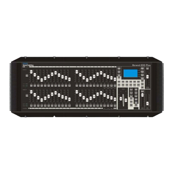
1. About this Guide The document provides installation and operation instructions for the following products: • 200 Plus 12/24 Control Console (LBE) - Strand Lighting Part Number 64331 • 200 Plus 24/48 Control Console (LBE) - Strand Lighting Model Number 64341 Please read all instructions before using this product. -
Page 7: 200 Plus Series Console Layout
200 Plus Series Console INTRODUCTION 1. 200 Plus Series Console Layout 12/24 Version Figure 2 illustrates the layout of the control features of the 200 Plus Series Console (12/24 version). See Detail A Channel Fader (1 - 24) Channel Expansion Keys Fader Flash Button (1 - 24) Detail A... -
Page 8: 24/48 Version
Operations Manual 24/48 Version Figure 3 illustrates the layout of the control features of the 200 Plus Series Console (24/48 version). See Detail A Channel Fader (1 - 48) Channel Expansion Keys Fader Flash Button (1 - 48) Detail A LCD Display Softkeys (A - D) Blackout Button LCD Display... -
Page 9: Glossary Of Terms
200 Plus Series Console 2. Glossary of Terms This section covers some of the common terms used throughout this manual. Channel Expansion Keys: Key 1-48 & Key 49-96 (Key 12-24 & Key 25- 48) Used to Page up/down for faders allowing the 24/48 console to control up to a maximum of 96 fader channels (maximum of 48 faders on the 12/24). -
Page 10: Getting Started
Operations Manual FD/ST TIME The Fader Time is available when the indicator is red. The Step Time is available when the indicator is yellow. Moving the Step Rate fader allows for a time to be set and stored in an FX stack. It is also possible to set times manually for all functions at any time. -
Page 11: Console Rear Panel Connections And Controls
200 Plus Series Console Console Rear Panel Connections and Controls Figure 4 identifies all the connections and controls on the rear panel of the 200 Plus Control Console. Detailed information is contained throughout the manual for each connection. Below is a list of connections and their purpose. Power Switch Power Input... -
Page 12: Connecting Dmx512
Operations Manual Step 2. Connect DC connector from power supply to DC IN on console. 200 Plus Series Console Rear Panel Power Input Connector Pinout 9 to 12 Volts DC 0.5 Amps (min.) Console On / Off Switch Power Input Connector Figure 5: 200 Plus Series Control Console Power Connection Step 3. -
Page 13: Video Monitor Connection
200 Plus Series Console 4. Video Monitor Connection The 200 plus series console comes equipped with a VGA monitor output card and drives any standard VGA monitor*. 200 Plus Series Console Rear Panel VGA Monitor Output (15-pin connector) Figure 7: 200 Plus Series Control Console VGA Connection. * Video monitor sold separately. -
Page 14: Console Basic Operation
Operations Manual CONSOLE BASIC OPERATION Naming Conventions When a key is referred to in the manual it will be in capital letters. For instance RECORD would refer to the record button. A softkey command on the LCD screen will be written contained inside "". So for instance the "Enter" would refer to a softkey option available on the LCD screen. - Page 15 200 Plus Series Console The monitor displays information (as shown in Figure 8) about Channel levels and the position of the A/B MASTER faders. REV1.00 Strand Lighting 2*48 GM: FL 01 02 03 04 05 06 07 08 09 10 11 12 13 14 15 16 17 18 19 20 21 22 23 24 25 26 27 28 29 30 31 32 33 34 35 36 37 38 39 40 41 42 43 44 45 46 47 48 49 50 51 52 53 54 55 56 57 58 59 60 61 62 63 64 65 66 67 68 69 70 71 72 73 74 75 76 77 78 79 80 81 82 83 84 85 86 87 88 89 90 91 92 93 94 95 96...
-
Page 16: Timed Operation
Operations Manual Example: 1) Make sure that the PRESET A MASTER and PRESET B MASTER faders are at the top. 2) Set PRESET A faders 1, 2 and 3 to 100%. (as you move these faders to 100% you will see the intensities of these channels turn on) 3) Set PRESET B faders 10, 11, 12 to 100%. -
Page 17: Flashing Channels
200 Plus Series Console 3) Set PRESET B faders 10, 11, 12 to 100%. 4) Ensure that the PRESET A and PRESET B faders have been selected in the LCD window. 5) Use the STEP RATE fader to set the desired time, 5 secs. 6) Move the PRESET A MASTER and PRESET B MASTER FADERS to the bottom quickly. -
Page 18: Entering Single Scene Operation Mode
Operations Manual If the video (VGA) display card is disconnected or a video monitor is not used, you can still view information on the LCD screen. Single Scene Menu A Fade Release DMX Base B Fade Master XXX Figure 12: Single Scene Operation - LCD Display Entering Single Scene Operation Mode There are two ways of entering Single Scene mode: If the SINGLE SCENE button is not lit at all:... -
Page 19: Timed Fades
200 Plus Series Console Example: 1) Press the NEXT button to select the crossfade mode for single scene operation. 2) Make sure that the PRESET A MASTER and PRESET B MASTER faders are at the top. 3) Set the faders 1, 2, 3, 22, 23 and 24 to 100%. (as you move these faders to 100% you will see the intensities of these channels come on) 4) Press the A STORE button. -
Page 20: Submaster Operation
Operations Manual To leave the crossfade function in Single Preset mode press the NEXT button when the PRESET A and PRESET B MASTER faders are at the top. This will turn out the red light and the A STORE and B STORE buttons will be inactive. -
Page 21: Changing Submaster Pages
200 Plus Series Console To set the time for a Submaster when recording it set the channels levels as described in recording submasters section. Press the RECORD button, set the time using the STEP RATE fader. The time will be shown in the lower left window of the LCD screen. -
Page 22: Playing Back Submasters Sequentially
Operations Manual To change pages, hold down the SUBMASTER button. The LCD screen will show the following: Submaster Mode Menu Assign Fade Fade Release Fade DMX Base P:01 Select 1 - 24 Figure 14: Submaster Mode - LCD Display The display in the lower left window shows that the console is on Page 1 (P:01) and that there are 24 pages available. To select a different page the Flash buttons 1 to 24 are used (1 to 12 on the 12/24 version). -
Page 23: Using Time To Playback Submasters Sequentially
200 Plus Series Console 2) Move PRESET A and PRESET B MASTERS to the bottom. 3) Press the NEXT key. It will turn blue. The flash button under Submaster 1 will flash yellow. 4) Raise the PRESET A and PRESET B MASTER faders. This will output Submaster 1 and its flash button will turn yellow. -
Page 24: Deleting Submasters
Operations Manual The LCD will show the time in the bottom Left window. Submaster Mode Menu Assign Fade Fade Release Fade DMX Base Fade Time: 1.90 Figure 16: Using Time to Playback Submasters Sequentially - LCD Display Deleting Submasters It is possible to delete individual Submasters, a complete page of Submasters, or all the recorded Submasters. To access any of these functions you need to be in Submaster mode and to have pressed the RECORD button. - Page 25 200 Plus Series Console Delete a Submaster Page To delete a whole page of Submasters press SOFTKEY B . You will need to select the Page required by holding down the SUBMASTER button and using the Flash button associated with the page you want to select it. The example of the LCD screen below shows that you are going to delete Page 01.
-
Page 26: Console Advanced Operation
Operations Manual CONSOLE ADVANCED OPERATION 1. Moving Light (ML) Mode It is possible to control up to 12 moving lights on the 12/24 console and 24 on the 24/48 console. Please be aware that this is a basic moving light console with limited features and control interface. It is seen as suitable for smaller shows that use moving lights occasionally and moving lights whose parameter set is limited. - Page 27 200 Plus Series Console • SOFTKEY B "Down" will lower the value • SOFTKEY C ">" is used to navigate between fields. To rapidly change values hold down the Softkey or use the SOLO fader to change the values extremely quickly. To store your changes use the SOFTKEY D for "Enter"...
-
Page 28: Using Your Moving Lights
Operations Manual • Use SOFTKEY D to select the fixture that you want. The LCD screen will change to allow you to set the start address for the fixture you have selected. Fixture Patch Other Menu Release Pat. ELA36LTB1 to DMX [215] Press Bump DMX Base Button To Patch... - Page 29 200 Plus Series Console REV1.00 Strand Lighting Moving Light GM: FL 01: STRPirouete 02: STRPirouete 03: STRPirouete 04: STRPirouete 05: STRPirouete 06: STRPirouete Pan: Pan: Pan: Pan: Pan: Pan: Tilt: 000 Tilt: Tilt: Tilt: Tilt: Tilt: Colour: Colour: Colour: Colour: Colour: Colour: Dimmer:...
- Page 30 Operations Manual Record Playback Menu Pan: Release Tilt: Color: Open Dimmer: DMX Base Gobo: Open Master: 255 Figure 26: Recording a Scene in a Moving Light - LCD Display 3) The Preset B Flash Buttons are used to store the look or sequence you wish to program. If a button has nothing recorded in it, it will flash.
- Page 31 200 Plus Series Console 6) The MENU Key can be used to return you to the ML home page. 7) You can now select an alternative moving light and set it as you require. It is possible to select multiple moving lights and control them at the same time.
- Page 32 Operations Manual Fixture Menu Modify Menu Playbk Release Invert Memory DMX Base Lock Back Master: xxx Figure 29: Editing a ML Scene or Chase - LCD Display Select SOFTKEY A "Modify Playbk" . You will get the information as shown in Figure 30 on the LCD display. Hit a Playbck Menu Pan:...
- Page 33 200 Plus Series Console To change which Scene you are editing you will need to use SOFTKEY D "Next" to move to the next Menu screen as illustrated in Figure 32. Modify Playback Menu Pan: Down Release Tilt: Color: Open Dimmer: Delete DMX Base...
- Page 34 Operations Manual Recording Groups To record a Group follow this sequence: 1) Select the fixture you want put it into the group using the fixture select buttons. 2) Press MENU button, then Press SOFTKEY C "Record Group" . 3) The Flash Buttons 1~24 (1-12 on the 12/24 version) will flash blue to indicate that no groups is stored in that button.
- Page 35 200 Plus Series Console Select the Master Focus Group you want by pressing the relevant softkey. This will allow you access to the Palettes associated with that fixture. Pressing the relevant softkey will select that palette. Figure 35 shows the LCD display screen for the Master Focus Group for Gobos.
-
Page 36: Further Ml Functions Available In The Menu Function
Operations Manual Use SOFTKEY D "Next" to access further functions. • SOFTKEY A "Speed" allows the user to set the speed at which the effect will run. To change the speed press and hold SOFTKEY A "Speed" key and then use the Step Rate Fader to set the speed that you require. •... -
Page 37: List Ml
200 Plus Series Console Deleting Fixtures To delete fixtures press SOFTKEY A "Delete Fix" . To delete all the fixtures select SOFTKEY B . You will be prompted to confirm this decision by pressing SOFTKEY A for "Yes" or SOFTKEY C for "No" . To select a single fixture select SOFTKEY A . -
Page 38: Led Mode
Operations Manual Note: To unlock the console either press the MENU or RECORD keys. This will prompt you to enter the password and unlock the console. 2. LED Mode It is possible to control up to 12 LEDs on the 12/24 console and 24 LEDs on the 24/48 console. A maximum of 20 Playbacks (8 Playbacks on the 12/24 version) can be recorded. - Page 39 200 Plus Series Console • To store your changes use SOFTKEY D "Enter" . Note: If you wish to leave this screen without storing any changes press the MENU button. It will return you to the previous screen. LED Patch First you need to allocate each LED fixture in your rig to a preset fader on the console.
-
Page 40: Programming Leds
Operations Manual It is possible to assign more than one fixture at the same time. If you wish to assign 4 fixtures of the same type, press and hold the flash button where you wish to store the first fixture. Then press the flash button representing the fourth fixture from the first fixture. -
Page 41: Record Playback
200 Plus Series Console REV1.00 Strand Lighting LED Mode GM: FL 01: XBandDA 02: XBandDA 03: XBandDA 04: XBandDA 05: XBandDA 06: XBandDA Red: Red: Pan: Pan: Pan: Pan: Green: Green: Green Green: Green: Green: Blue: Blue: Blue: Blue: Blue: Blue: 07: PLBlaze 08: PLBlaze... - Page 42 Operations Manual 7) Once you have set all the LEDs you require press the Playback button you had previously selected. (It is the one that is flashing on the Preset B row of flash buttons.) 8) This will store the first scene. If you only wish to have a single scene, press the RECORD key. This will save the scene.
- Page 43 200 Plus Series Console You will need to go to the third page of the LED menus. To do this, use the SOFTKEY D "Next" after pressing the MENU key. This will take you to the LCD display as shown in Figure 43. Led Menu Mode Modify Menu...
- Page 44 Operations Manual The bottom left of the LCD screen shows which playback you are editing, which scene you are in and the total number of scenes. In the example above we are editing Playback 1, we are in Scene 8 and there are a Total of 11 scenes.
- Page 45 200 Plus Series Console Recording Groups To record a Group, follow this sequence: 1) Select the LEDs you want put it into the group using the fixture select buttons. 2) Press MENU button, then Press SOFTKEY C "Record Group" . 3) The Flash Buttons 1~24 (1-12 on the 12/24 version) will flash blue to indicate that no groups are stored in a button.
- Page 46 Operations Manual • SOFTKEY D "Run!" will start the rainbow. • To change the number of colors, the color size or the speed SOFTKEY A "Item Set" allows you to select the rele- vant field. The FX keys can then be used to enter a value of between 1 and 10 for the Color Number or size. The Speed can be set using the STEP RATE fader.
-
Page 47: Further Ml Functions Available In The Menu Setting
200 Plus Series Console Note: Anytime you are in a menu and wish to leave it please use the MENU key to go back to the previous menu screen. Further ML Functions available in the Menu Setting Delete The Delete function allows you to delete a scene or chase or a LED from the patch. To access Delete you need to Press the MENU key while in LED mode. -
Page 48: Memory Lock
Operations Manual Memory Lock This allows the user to lock the console using a password to stop any changes being made to the console. The password is entered using the FX keys. (See section in Setup chapter on setting passwords). Memory Lock is accessed by pressing the MENU key and then going to the third page of menus using the SOFTKEY D "Next"... -
Page 49: Memory Playback
200 Plus Series Console MEMORY PLAYBACK 1. Memory Playback Mode Memory playback mode is entered by pressing the MEM PLAYBACK key. You will be prompted to use SOFTKEY A "Yes" to enter this mode. If you do not wish to enter use SOFTKEY C "No". Memory Playback Mode allows you to combine Submasters with the LED and ML scenes or chases that you have recorded. -
Page 50: Fx Mode
Operations Manual FX MODE FX mode allows you to program channels, MLs and LEDs into a single cue stack. These stacks can have a time for each scene and also a wait time for each scene if you want them to run automatically. If the cue stack is recorded with the Step Time set to Manual then it can be run using the GO/STEP button to trigger each step. - Page 51 200 Plus Series Console REV1.00 Strand Lighting 1*96 GM: FL 01 02 03 04 05 06 07 08 09 10 11 12 13 14 15 16 17 18 19 20 21 22 23 24 75 75 75 75 25 26 27 28 29 30 31 32 33 34 35 36 37 38 39 40 41 42 43 44 45 46 47 48 49 50 51 52 53 54 55 56 57 58 59 60 61 62 63 64 65 66 67 68 69 70 71 72 73 74 75 76 77 78 79 80 81 82 83 84 85 86 87 88 89 90 91 92 93 94 95 96 Submaster...
-
Page 52: Combining Mls, Leds And Channels
Operations Manual 7) Press Flash Button 1 . It will go out. The first scene is now stored in this button. 8) Set channels 5 to 8 at FL . 9) Set the FD/ST TIME button to Step mode (it will be yellow). Set the STEP RATE Fader to 2.00, you can see the step time changing in the lower left window of the LCD. -
Page 53: Copying A Scene
200 Plus Series Console Copying a Scene It is possible to copy a scene from one scene to another in an FX stack. 1) To access this function press RECORD and then the FX you wish to work with. The FX button will flash blue. -
Page 54: Editing A Scene
Operations Manual 5) Set the scene you require in the normal way by setting Channels, MLs and LEDs. 6) Hold down the flash button where you wish to store the scene. 7) Press SOFTKEY D "Cover" to store the scene. 8) Exit by pressing SOFTKEY C "Record FXBase"... -
Page 55: Deleting An Fx
200 Plus Series Console 4) The scene previously stored in that button will be deleted and the flash button will flash red to show it is empty. 5) Exit by pressing SOFTKEY C "Record FXBase" to update the FX stack. 5. - Page 56 Operations Manual 8) To exit preview press SOFTKEY A "Preview" . It will go back to normal. 9) Use SOFTKEY D "Exit" to leave the function. FX MODE...
-
Page 57: Set Up Functions
200 Plus Series Console SET UP FUNCTIONS All the set up functions are accessed by pressing the MENU key when in Single Scene, Two Scene or Submaster modes. 1. DMX Settings When you press Menu the LCD display will appear as shown in Figure 59. Menu Chan Menu... -
Page 58: Channel Patch
Operations Manual In DMX Patch, you have three options: • Channel Patch. This allows you to allocate the DMX addresses you wish to control to any of the 96 channel faders available (48 on the 12/24 version). • DMX Patch. This function is similar to the above but allows you to work in the opposite way by assigning a spe- cific DMX address to a channel fader. -
Page 59: Dmx Patch (Associate An Address With A Channel)
200 Plus Series Console • To exit without saving the changes press MENU . DMX Patch (Associate an Address with a Channel) This function allows you to associate a DMX address with a channel. Use SOFTKEY B "DMX Patch" to select the function. The LCD display will appear as shown in Figure 63. address Patch Menu Patch By Dimmer... -
Page 60: Update Vga
Operations Manual 4) The Software will begin loading. 4. Update VGA In the future there may be updates of the VGA screens. It is on the second page of the Menu screens. You also need to insert the USB key (preloaded with the software) into the USB port on the rear panel of the console. To access VGA update: 1) Press MENU key. - Page 61 200 Plus Series Console Note: If you want to create your own show or edit one of the ones provided with the console, you will need Strand 200 Flash Tools. You can also download Strand 200 Flash Tools from the Strand Web Site at www.strandlighting.com.
-
Page 62: Dmx In Show
Operations Manual The show will run in the preview window. Figure 66 illustrates the preview screen. Figure 66: Preview Screen You can change the number of fixtures that the show is applied to by selecting the Point window on the top left of the screen. - Page 63 200 Plus Series Console 4) You have two choices for recording. BBT Record will record the incoming DMX stream until all channel are set to "Zero:" This mode has two options ( Auto Record and Manual Record ). a. Auto Record . This mode will stop recording the DMX stream as soon as it sees a Blackout . b.
- Page 64 Operations Manual BBT Record You will need to be in DMX Base mode. You will need to have an external DMX512 source plugged into the DMX In connection in the rear panel of the console. BBT Auto Record To perform a BBT Auto Record: 1) Press RECORD .
- Page 65 200 Plus Series Console 6) The timer will begin as soon as the console sees a DMX change happening and recording will start. 7) The recording will stop as soon as the console sees a blackout on the incoming DMX stream. 8) To play back your show press the FX Key it is stored in.
-
Page 66: Vga Set
Operations Manual 3) Select SOFTKEY D "DelALL" . 4) Select SOFTKEY A "Yes" to delete or SOFTKEY C "No" to exit without deleting. Delete Single DMX Base You will need to be in DMX Base mode. To delete a single DMX base: 1) Press RECORD . -
Page 67: Upload Library
200 Plus Series Console 4) SOFTKEY A "OpPoll" will pole the network for ArtNet Devices. 5) SOFTKEY B "View Device" will allow you to view all the ArtNet Devices on the network. 6) SOFTKEY C "ArtNet Config" is used to configure the ArtNet Network. The LCD display will appear as shown in Figure 76. -
Page 68: System Files
Operations Manual • SOFTKEY B "Fix Upload" will upload only the Fixture Information. • SOFTKEY C "SubMst Upload" will upload only the Submaster information. • SOFTKEY D "Next" will bring up further options as shown in Figure 78. Upload Lib Menu Upload Release... -
Page 69: Change Password
200 Plus Series Console • SOFTKEY B "Fix DwLoad" will load all the fixture information to the console. • SOFTKEY C "SubMst DwLoad" will load all the submaster information to the console. • SOFTKEY D "Next" will bring up further options as shown in Figure 81. System Files System Menu... -
Page 70: Master Password
Operations Manual 6) Your new password is stored in the console. Please store your new password in a safe location. Strand Lighting does not keep a record of user-defined passwords. 11. Master Password For any reason, should the user no longer remember the user assigned password, there is a Master Password that is 861861 available that will allow access in order to reset the password. -
Page 71: Unlocking The Console
200 Plus Series Console Unlocking the Console To unlock the console: 1) Press MENU or RECORD . The LCD display will appear as shown in Figure 82. Memory Lock Unlock Menu Memory Release Memory Locked DMX Base Exit GM xxx Figure 82: Memory Unlock - LCD Display 2) Use SOFTKEY A "Unlock Memory"... -
Page 72: Creating Moving Light (Ml) And Led Fixture Libraries
Operations Manual CREATING MOVING LIGHT (ML) AND LED FIXTURE LIBRARIES Strand makes every effort to provide up to date fixture libraries but as manufacturers regularly launch new fixtures you may not always have a fixture profile when you need it. We have provided a tool to allow you to create your own fixture as you require. - Page 73 200 Plus Series Console 7) Once you have set all the channels it is possible to use the Channel Traits screen to set the steps for a channel. For instance, the moving light may have a colour wheel where the DMX value for each colour is given.
-
Page 74: Technical Specifications Electrical
200 plus 24/48 21.0 lbs / 9.5 kg Dimensions (LxWxH): 200 plus 12/24 (64331): 22.4 x 12.5 x 3.1 in / 568.0 x 318.0 x 79.4 mm 200 plus 24/48 (64341): 31.7 x 12.5 x 3.1 in / 804.0 x 318.0 x 79.4 mm 200 Plus 12/24 Console 3.1 in. - Page 75 200 Plus Series Console Notes Mechanical...
Need help?
Do you have a question about the 64331 and is the answer not in the manual?
Questions and answers