
Related Manuals for Mitsubishi Electric MR-JE-_A


Summary of Contents for Mitsubishi Electric MR-JE-_A
- Page 1 General-Purpose AC Servo General-Purpose Interface AC Servo MODEL MR-JE-_A SERVO AMPLIFIER INSTRUCTION MANUAL...
-
Page 2: Safety Instructions
Safety Instructions Please read the instructions carefully before using the equipment. To use the equipment correctly, do not attempt to install, operate, maintain, or inspect the equipment until you have read through this Instruction Manual, Installation guide, and appended documents carefully. Do not use the equipment until you have a full knowledge of the equipment, safety information and instructions. - Page 3 1. To prevent electric shock, note the following WARNING Before wiring and inspections, turn off the power and wait for 15 minutes or more until the charge lamp turns off. Otherwise, an electric shock may occur. In addition, when confirming whether the charge lamp is off or not, always confirm it from the front of the servo amplifier.
- Page 4 4. Additional instructions The following instructions should also be fully noted. Incorrect handling may cause a malfunction, injury, electric shock, fire, etc. (1) Transportation and installation CAUTION Transport the products correctly according to their mass. Stacking in excess of the specified number of product packages is not allowed. Do not hold the lead of the built-in regenerative resistor, cables, or connectors when carrying the servo amplifier.
- Page 5 (2) Wiring CAUTION Before removing the CNP1 connector of MR-JE-40A to MR-JE-100A, disconnect the lead wires of the regenerative resistor from the CNP1 connector. Wire the equipment correctly and securely. Otherwise, the servo motor may operate unexpectedly. Make sure to connect the cables and connectors by using the fixing screws and the locking mechanism. Otherwise, the cables and connectors may be disconnected during operation.
- Page 6 CAUTION Never adjust or change the parameter values extremely as it will make operation unstable. Do not get close to moving parts during the servo-on status. (4) Usage CAUTION When it is assumed that a hazardous condition may occur due to a power failure or product malfunction, use a servo motor with an external brake to prevent the condition.
- Page 7 CAUTION Configure an electromagnetic brake circuit which is interlocked with an external emergency stop switch. Contacts must be opened when ALM Contacts must be opened (Malfunction) or MBR (Electromagnetic with the emergency stop switch. brake interlock) turns off. Servo motor 24 V DC Electromagnetic brake To prevent an electric shock, injury, or fire from occurring after an earthquake or other natural disasters,...
- Page 8 Manual No. MELSERVO-JE Servo Amplifier Instruction Manual (Troubleshooting) SH(NA)030166ENG MELSERVO MR-JE-_A Servo Amplifier Instruction Manual (Positioning Mode) SH(NA)030150ENG MELSERVO MR-JE-_A Servo Amplifier Instruction Manual (Modbus RTU Protocol) SH(NA)030177ENG MELSERVO HG-KN/HG-SN Servo Motor Instruction Manual SH(NA)030135ENG MELSERVO EMC Installation Guidelines IB(NA)67310ENG «Cables used for wiring»...
- Page 9 MEMO A - 8...
-
Page 10: Table Of Contents
CONTENTS 1. FUNCTIONS AND CONFIGURATION 1- 1 to 1-14 1.1 Summary ............................1- 1 1.2 Function block diagram ........................1- 2 1.3 Servo amplifier standard specifications .................... 1- 4 1.4 Combinations of servo amplifiers and servo motors ................ 1- 6 1.5 Function list ............................ - Page 11 3.8.2 When you do not use the forced stop deceleration function ............. 3-52 3.9 Interfaces ............................3-53 3.9.1 Internal connection diagram ...................... 3-53 3.9.2 Detailed explanation of interfaces ..................... 3-55 3.9.3 Source I/O interfaces ........................ 3-59 3.10 Servo motor with an electromagnetic brake .................. 3-61 3.10.1 Safety precautions ........................
- Page 12 5.1.1 Basic setting parameters ([Pr. PA_ _ ]) ..................5- 2 5.1.2 Gain/filter setting parameters ([Pr. PB_ _ ]) ................5- 2 5.1.3 Extension setting parameters ([Pr. PC_ _ ]) ................5- 4 5.1.4 I/O setting parameters ([Pr. PD_ _ ]) ..................5- 5 5.1.5 Extension setting 2 parameters ([Pr.
- Page 13 11.9 Noise reduction techniques ......................11-22 11.10 Earth-leakage current breaker ....................11-28 11.11 EMC filter (recommended) ......................11-30 12. COMMUNICATION FUNCTION (MITSUBISHI ELECTRIC GENERAL-PURPOSE AC SERVO PROTOCOL) 12- 1 to 12-34 12.1 Structure ............................12- 1 12.1.1 Configuration diagram ......................12- 1...
- Page 14 12.2 Communication specifications ...................... 12- 3 12.2.1 Outline of communication ...................... 12- 3 12.2.2 Parameter setting ........................12- 3 12.3 Protocol ............................12- 4 12.3.1 Transmission data configuration .................... 12- 4 12.3.2 Character codes ........................12- 5 12.3.3 Error codes ..........................12- 6 12.3.4 Checksum ..........................
- Page 15 MEMO...
-
Page 16: Functions And Configuration
1. FUNCTIONS AND CONFIGURATION 1.1 Summary The Mitsubishi Electric general-purpose AC servo MELSERVO-JE series have limited functions with keeping high performance based on MELSERVO-J4 series. The servo amplifier has position, speed, and torque control modes. In the position control mode, the maximum pulse train of 4 Mpulses/s is supported. -
Page 17: Function Block Diagram
1. FUNCTIONS AND CONFIGURATION 1.2 Function block diagram The function block diagram of this servo is shown below. (1) MR-JE-100A or less Regenerative option Servo motor Diode Dynamic stack Relay brake circuit (Note 1) MCCB (Note 2) Current Power Regene- encoder supply rative... - Page 18 1. FUNCTIONS AND CONFIGURATION (2) MR-JE-200A or more Regenerative option Servo motor Diode Dynamic stack brake circuit Relay MCCB (Note) Current Power encoder Regene- supply rative CHARGE lamp Cooling fan Electromagnetic 24 V DC brake Control circuit Base Voltage Current power Overcurrent amplifier...
-
Page 19: Servo Amplifier Standard Specifications
Speed limit Set by parameter setting or external analog input (0 V DC to 10 V DC/rated speed) Refer to section 1.1 of "MR-JE-_A Servo Amplifier Instruction Manual (Positioning Mode)" Positioning mode The positioning mode is available with servo amplifiers with software version B7 or later. - Page 20 1. FUNCTIONS AND CONFIGURATION Model: MR-JE- 100A 200A 300A Operation 0 °C to 55 °C (non-freezing) Ambient temperature Storage -20 °C to 65 °C (non-freezing) Operation Ambient 5 %RH to 90 %RH (non-condensing) humidity Storage Environment Indoors (no direct sunlight), Ambience free from corrosive gas, flammable gas, oil mist, dust, and dirt Altitude...
-
Page 21: Combinations Of Servo Amplifiers And Servo Motors
1. FUNCTIONS AND CONFIGURATION 1.4 Combinations of servo amplifiers and servo motors Servo amplifier Servo motor MR-JE-10A HG-KN13_ MR-JE-20A HG-KN23_ MR-JE-40A HG-KN43_ MR-JE-70A HG-KN73_ HG-SN52_ MR-JE-100A HG-SN102_ MR-JE-200A HG-SN152_ HG-SN202_ MR-JE-300A HG-SN302_ 1 - 6... -
Page 22: Function List
Section 3.6.6 mode control. MR-JE-_A Servo In this mode, MR-JE-_A servo amplifiers are used in with point table or program Amplifier method. For details, refer to "MR-JE-_A Servo Amplifier Instruction Manual Positioning mode Instruction (Positioning Mode)." The positioning mode is available with servo amplifiers with Manual software version B7 or later. - Page 23 This is used with servo amplifiers with software version C5 or Section 7.5 function later. Check the software version of the servo amplifier using MR Configurator2. MR-JE-_A Servo The Modbus protocol uses dedicated message frames for the serial communication Amplifier Modbus RTU communication between a master and slaves.
-
Page 24: Model Designation
1. FUNCTIONS AND CONFIGURATION 1.6 Model designation (1) Rating plate The following shows an example of rating plate for explanation of each item. AC SERVO Serial number SER. S4Y001001 Model MR-JE-10A Capacity POWER : 100W Applicable power supply INPUT : 3AC/200-240V 0.9A/1.5A 50/60Hz Rated output current OUTPUT : 3PH170V 0-360Hz 1.1A... -
Page 25: Structure
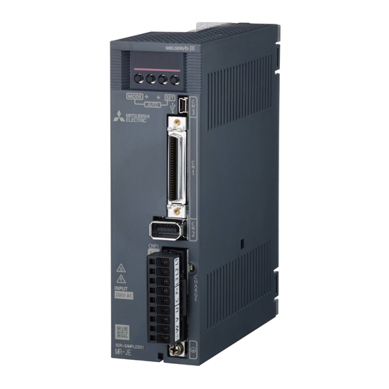
1. FUNCTIONS AND CONFIGURATION 1.7 Structure 1.7.1 Parts identification (1) MR-JE-100A or less Detailed Name/Application explanati Display Section The 5-digit, 7-segment LED shows the servo status and the alarm number. Operation section Used to perform status display, diagnostic, alarm, and parameter setting operations. Push the "MODE" and "SET"... - Page 26 1. FUNCTIONS AND CONFIGURATION (2) MR-JE-200A or more Detailed Name/Application explanati Display Section The 5-digit, 7-segment LED shows the servo status and the alarm number. Operation section Used to perform status display, diagnostic, alarm, and parameter setting operations. Push the "MODE" and "SET"...
-
Page 27: Configuration Including Peripheral Equipment
1. FUNCTIONS AND CONFIGURATION 1.8 Configuration including peripheral equipment Connecting a servo motor of the wrong axis to U, V, W, or CN2 of the servo CAUTION amplifier may cause a malfunction. POINT Equipment other than the servo amplifier and servo motor are optional or recommended products. - Page 28 1. FUNCTIONS AND CONFIGURATION (2) MR-JE-200A or more The diagram shows MR-JE-200A. R S T (Note 1) Power supply Molded-case circuit breaker Personal computer MR Configurator2 (Note 2) Magnetic contactor (MC) Power factor improving AC reactor (FR-HAL) Line noise filter (FR-BSF01) Junction terminal block Servo motor...
- Page 29 1. FUNCTIONS AND CONFIGURATION MEMO 1 - 14...
-
Page 30: Installation
2. INSTALLATION 2. INSTALLATION WARNING To prevent electric shock, ground each equipment securely. Stacking in excess of the specified number of product packages is not allowed. Do not hold the lead of the built-in regenerative resistor, cables, or connectors when carrying the servo amplifier. Otherwise, it may drop. Install the equipment on incombustible material. -
Page 31: Installation Direction And Clearances
2. INSTALLATION 2.1 Installation direction and clearances The equipment must be installed in the specified direction. Otherwise, it may cause a malfunction. CAUTION Leave specified clearances between the servo amplifier and the cabinet walls or other equipment. Otherwise, it may cause a malfunction. MR-JE-40A to MR-JE-100A have a regenerative resistor on their back face. -
Page 32: Keep Out Foreign Materials
2. INSTALLATION (b) Installation of two or more servo amplifiers POINT Close mounting is possible depending on the capacity of the servo amplifier. Refer to section 1.3 for availability of close mounting. Leave a large clearance between the top of the servo amplifier and the cabinet walls, and install a cooling fan to prevent the internal temperature of the cabinet from exceeding the environment. -
Page 33: Encoder Cable Stress
2. INSTALLATION 2.3 Encoder cable stress (1) The way of clamping the cable must be fully examined so that bending stress and cable's own weight stress are not applied to the cable connection. (2) For use in any application where the servo motor moves, fix the cables (encoder, power supply, and brake) with having some slack from the connector connection part of the servo motor to avoid putting stress on the connector connection part. -
Page 34: Parts Having Service Life
2. INSTALLATION 2.5 Parts having service life Service life of the following parts is listed below. However, the service life varies depending on operating methods and environment. If any fault is found in the parts, they must be replaced immediately regardless of their service life. -
Page 35: Restrictions When Using This Product At Altitude Exceeding 1000 M And Up To 2000 M Above Sea Level
2. INSTALLATION 2.6 Restrictions when using this product at altitude exceeding 1000 m and up to 2000 m above sea level (1) Effective load ratio and regenerative load ratio As heat dissipation effects decrease in proportion to the decrease in air density, use the product within the effective load ratio and regenerative load ratio shown in the following figure. -
Page 36: Signals And Wiring
3. SIGNALS AND WIRING 3. SIGNALS AND WIRING Any person who is involved in wiring should be fully competent to do the work. Before wiring, turn off the power and wait for 15 minutes or more until the charge lamp turns off. Otherwise, an electric shock may occur. In addition, when confirming whether the charge lamp is off or not, always confirm it from the front of the servo amplifier. -
Page 37: Input Power Supply Circuit
3. SIGNALS AND WIRING Connecting a servo motor of the wrong axis to U, V, W, or CN2 of the servo amplifier may cause a malfunction. CAUTION Before wiring, switch operation, etc., eliminate static electricity. Otherwise, it may cause a malfunction. 3.1 Input power supply circuit Always connect a magnetic contactor between the power supply and the power supply (L1/L2/L3) of the servo amplifier, in order to configure a circuit that shuts... - Page 38 3. SIGNALS AND WIRING (1) Using 3-phase 200 V AC to 240 V AC power supply for MR-JE-10A to MR-JE-100A Emergency stop switch Malfunction Servo amplifier Servo motor (Note 5) MCCB CNP1 3-phase (Note 4, 7) Built-in 200 V AC to Motor regenerative 240 V AC...
- Page 39 3. SIGNALS AND WIRING (2) Using 1-phase 200 V AC to 240 V AC power supply for MR-JE-10A to MR-JE-100A POINT Connect the 1-phase 200 V AC to 240 V AC power supply to L1 and L3. One of the connecting destinations is different from MR-JE-200A Servo Amplifier's. You can use the neutral point of a 3-phase 400 V AC class power supply to input a 1-phase 200 V AC class power supply to the servo amplifier.
- Page 40 3. SIGNALS AND WIRING (3) Using 3-phase 200 V AC to 240 V AC power supply for MR-JE-200A or MR-JE-300A Emergency stop switch Malfunction Servo amplifier Servo motor (Note 5) MCCB CNP1 3-phase CNP2 (Note 4, 7) 200 V AC to Motor 240 V AC Unassigned...
- Page 41 3. SIGNALS AND WIRING (4) Using 1-phase 200 V AC to 240 V AC power supply for MR-JE-200A POINT Connect the 1-phase 200 V AC to 240 V AC power supply to L1 and L2. One of the connecting destinations is different from MR-JE-100A or less Servo Amplifier's.
-
Page 42: I/O Signal Connection Example
3. SIGNALS AND WIRING 3.2 I/O signal connection example 3.2.1 Position control mode (1) When you use a positioning module LD75D/QD75D/RD75D (a) For sink I/O interface Servo amplifier 24 V DC (Note 4) (Note 7) Positioning module 24 V DC (Note 4) LD75D/QD75D/RD75D (Note 7) DOCOM... - Page 43 3. SIGNALS AND WIRING Note 1. To prevent an electric shock, always connect the protective earth (PE) terminal (marked ) of the servo amplifier to the protective earth (PE) of the cabinet. 2. Connect the diode in the correct direction. If it is connected reversely, the servo amplifier will malfunction and will not output signals, disabling EM2 (Forced stop 2) and other protective circuits.
- Page 44 3. SIGNALS AND WIRING (b) For source I/O interface POINT For notes, refer to (1) (a) in this section. Servo amplifier 24 V DC (Note 4, 12) (Note 7) Positioning module 24 V DC (Note 4, 12) RD75D (Note 7) DOCOM (Note 2) DICOM...
- Page 45 3. SIGNALS AND WIRING (2) When you use a positioning module FX -_ _MT/ES (For sink I/O interface) 2 m or less (Note 8) Programmable controller -_ _MT/ES (Note 11) Servo amplifier (Note 7) (Note 7) 24 V DC 24 V DC (Note 4) Programmable (Note 4) DICOM...
- Page 46 3. SIGNALS AND WIRING Note 1. To prevent an electric shock, always connect the protective earth (PE) terminal (marked ) of the servo amplifier to the protective earth (PE) of the cabinet. 2. Connect the diode in the correct direction. If it is connected reversely, the servo amplifier will malfunction and will not output signals, disabling EM2 (Forced stop 2) and other protective circuits.
-
Page 47: Speed Control Mode
3. SIGNALS AND WIRING 3.2.2 Speed control mode (1) For sink I/O interface Servo amplifier (Note 7) 24 V DC (Note 4) DOCOM DOCOM (Note 2) 10 m or less (Note 7) Malfunction (Note 6) (Note 10) Power supply Zero speed detection (Note 3, 5) Forced stop 2 Servo-on... - Page 48 3. SIGNALS AND WIRING (2) For source I/O interface POINT For notes, refer to (1) in this section. Servo amplifier (Note 7) 24 V DC (Note 4, 11) DOCOM DOCOM (Note 2) 10 m or less Malfunction (Note 6) (Note 7) (Note 10) Power supply Zero speed detection...
-
Page 49: Torque Control Mode
3. SIGNALS AND WIRING 3.2.3 Torque control mode POINT EM2 has the same function as EM1 in the torque control mode. (1) For sink I/O interface Servo amplifier (Note 6) 24 V DC (Note 4) DOCOM DOCOM (Note 2) 10 m or less Malfunction (Note 6) (Note 6) (Note 8) - Page 50 3. SIGNALS AND WIRING (2) For source I/O interface POINT For notes, refer to (1) in this section. Servo amplifier (Note 6) 24 V DC (Note 4, 9) DOCOM DOCOM (Note 2) 10 m or less Malfunction (Note 5) (Note 6) (Note 8) Power supply Zero speed detection...
-
Page 51: Explanation Of Power Supply System
3. SIGNALS AND WIRING 3.3 Explanation of power supply system 3.3.1 Signal explanations POINT For the layout of connector and terminal block, refer to chapter 9 DIMENSIONS. Connection target Symbol Description (application) Supply the following power to L1/L2/L3. For 1-phase 200 V AC to 240 V AC, connect the power supply to L1 and L3. -
Page 52: Power-On Sequence
3. SIGNALS AND WIRING 3.3.2 Power-on sequence POINT The voltage of analog monitor output, output signal, etc. may be unstable at power-on. (1) Power-on procedure 1) Always wire the power supply as shown in above section 3.1 using the magnetic contactor with the power supply (L1/L2/L3). -
Page 53: Wiring Cnp1 And Cnp2
3. SIGNALS AND WIRING 3.3.3 Wiring CNP1 and CNP2 POINT For the wire sizes used for wiring, refer to section 11.5. When wiring, remove the power connectors from the servo amplifier. Insert only one wire or ferrule to each wire insertion hole. To wire to CNP1 and CNP2, use servo amplifier power connectors packed with the amplifier or optional connectors (refer to section 11.1.1). - Page 54 3. SIGNALS AND WIRING (2) Cable connection procedure (a) Fabrication on cable insulator Refer to table 3.1 and 3.2 for stripped length of cable insulator. The appropriate stripped length of cables depends on their type, etc. Set the length considering their status. Insulator Core Stripped length...
-
Page 55: Connectors And Pin Assignment
3. SIGNALS AND WIRING 3.4 Connectors and pin assignment POINT The pin assignment of the connectors is as viewed from the cable connector wiring section. For the CN1 connector, securely connect the external conductor of the shielded cable to the ground plate and fix it to the connector shell. Screw Cable Screw... - Page 56 3. SIGNALS AND WIRING The device assignment of CN1 connector pins changes depending on the control mode. For the pins which are given parameters in the related parameter column, their devices will be changed using those parameters. (Note 2) I/O signals in control modes (Note 1) Pin No.
- Page 57 3. SIGNALS AND WIRING (Note 2) I/O signals in control modes (Note 1) Pin No. Related parameter DOCOM DOCOM DOCOM DOCOM DOCOM DOCOM DOCOM DOCOM DOCOM DOCOM DOCOM DOCOM PD28 Note 1. I: input signal, O: output signal 2. P: position control mode, S: speed control mode, T: torque control mode, P/S: position/speed control switching mode, S/T: speed/torque control switching mode, T/P: torque/position control switching mode 3.
-
Page 58: Signal (Device) Explanations
3. SIGNALS AND WIRING 3.5 Signal (device) explanations For the I/O interfaces (symbols in I/O division column in the table), refer to section 3.9.2. In the control mode field of the table P: position control mode, S: speed control mode, T: torque control mode Torque control mode : devices used with initial setting status, : devices used by setting [Pr. - Page 59 3. SIGNALS AND WIRING Control Connector mode Device Symbol Function and application pin No. division Forward rotation CN1-43 To start operation, turn on LSP and LSN. Turn it off to bring the motor to a DI-1 stroke sudden stop and make it servo-locked. Setting [Pr.
- Page 60 3. SIGNALS AND WIRING Control Connector mode Device Symbol Function and application pin No. division Forward rotation Select a servo motor torque generation directions. DI-1 selection The following shows the torque generation directions. (Note) Input device Torque generation direction Torque is not generated. Reverse rotation Forward rotation in power selection...
- Page 61 3. SIGNALS AND WIRING Control Connector mode Device Symbol Function and application pin No. division Proportion Turn PC on to switch the speed amplifier from the proportional integral type DI-1 control to the proportional type. If the servo motor at a stop is rotated even one pulse due to any external factor, it generates torque to compensate for a position shift.
- Page 62 3. SIGNALS AND WIRING Control Connector mode Device Symbol Function and application pin No. division Control switching «Position/speed control switching mode» DI-1 Refer to Function This is used to select the control mode in the position/speed control switching mode. application. (Note) Control mode...
- Page 63 3. SIGNALS AND WIRING (b) Output device Control Connector mode Device Symbol Function and application pin No. division Malfunction CN1-48 When an alarm occurs, ALM will turn off. DO-1 When an alarm does not occur, ALM will turn on after 2.5 s to 3.5 s after power-on.
- Page 64 3. SIGNALS AND WIRING Control Connector mode Device Symbol Function and application pin No. division DO-1 Alarm code ACD0 (CN1-24) To use these signals, set " _ _ _ 1" in [Pr. PD34]. This signal is outputted when an alarm occurs. When an alarm is not occurring, respective ordinary signals are outputted.
- Page 65 3. SIGNALS AND WIRING (3) Output signal Control Connector mode Device Symbol Function and application pin No. division Encoder A- CN1-4 These devices output pulses of encoder output pulse set in [Pr. PA15] in DO-2 phase pulse the differential line driver type. CN1-5 (differential line In CCW rotation of the servo motor, the encoder B-phase pulse lags the...
- Page 66 3. SIGNALS AND WIRING (5) Power supply Control Connector mode Device Symbol Function and application pin No. division Digital I/F power DICOM CN1-20 Input 24 V DC (24 V DC ± 10% 300 mA) for I/O interface. The power supply input supply capacity changes depending on the number of I/O interface points CN1-21 to be used.
-
Page 67: Detailed Explanation Of Signals
Adjust the logic of a positioning module and command pulse as follows. MELSEC iQ-R series/MELSEC-Q series/MELSEC-L series positioning module Command pulse logic setting Signal type Positioning module MR-JE-_A servo amplifier Pr. 23 setting [Pr. PA13] setting Positive logic Positive logic (_ _ 0 _) Open-collector type... - Page 68 3. SIGNALS AND WIRING The following section explains about the case where the negative logic and the forward/reverse rotation pulse trains are set to "_ _ 1 0" in [Pr. PA13]. (ON) (ON) (ON) (OFF) (OFF) (OFF) Forward rotation pulse train (transistor) Reverse rotation pulse train (OFF)
- Page 69 3. SIGNALS AND WIRING (2) INP (In-position) INP turns on when the number of droop pulses in the deviation counter falls within the preset in-position range ([Pr. PA10]). INP may turn on continuously during a low-speed operation with a large value set as the in-position range.
- Page 70 3. SIGNALS AND WIRING (5) Torque limit If the torque limit is canceled during servo-lock, the servo motor may suddenly rotate according to position deviation in respect to the command position. CAUTION When using the torque limit, check that [Pr. PB06 Load to motor inertia ratio] is set properly.
- Page 71 3. SIGNALS AND WIRING Input device (Note 1) Enabled torque limit value Limit value status CCW power running/CW CW power running/CCW regeneration regeneration Pr. PA11 Pr .PA12 Pr. PA11 > Pr. PA11 Pr. PA12 Pr. PA12 Pr. PA11 < TLA (Note 2) TLA (Note 3) Pr.
-
Page 72: Speed Control Mode
3. SIGNALS AND WIRING 3.6.2 Speed control mode (1) Speed setting (a) Speed command and speed The servo motor is run at the speeds set in the parameters or at the speed set in the applied voltage of VC (Analog speed command). A relation between VC (Analog speed command) applied voltage and the servo motor speed is as follows. - Page 73 3. SIGNALS AND WIRING (b) Speed command value selection To select VC (Analog speed command) and a speed command value of internal speed commands 1 to 7, enable SP1 (Speed selection 1), SP2 (Speed selection 2), and SP3 (Speed selection 3) with [Pr.
-
Page 74: Torque Control Mode
3. SIGNALS AND WIRING 3.6.3 Torque control mode (1) Torque limit (a) Torque command and torque The following shows a relation between the applied voltage of TC (Analog torque command) and the torque by the servo motor. The maximum torque is generated at ±8 V. The speed at ±8 V can be changed with [Pr. PC13]. CCW direction Forward rotation Maximum torque... - Page 75 3. SIGNALS AND WIRING (b) Analog torque command offset Using [Pr. PC38], the offset voltage of -9999 mV to 9999 mV can be added to the TC applied voltage as follows. Maximum torque Torque [Pr. PC38] offset range -9999 mV to 9999 mV 8 (-8) TC applied voltage [V] (2) Torque limit...
- Page 76 3. SIGNALS AND WIRING Normally, connect as follows. Servo amplifier -10 V to +10 V (b) Speed limit value selection To select VLA (Analog speed limit) and a speed limit value of internal speed limit 1 to 7, enable SP1 (Speed selection 1), SP2 (Speed selection 2), and SP3 (Speed selection 3) with [Pr.
-
Page 77: Position/Speed Control Switching Mode
3. SIGNALS AND WIRING 3.6.4 Position/speed control switching mode Set " _ _ _ 1" in [Pr. PA01] to switch to the position/speed control switching mode. (1) LOP (control switching) Use LOP (Control switching) to switch between the position control mode and the speed control mode with an external contact. - Page 78 3. SIGNALS AND WIRING (3) Speed setting in speed control mode (a) Speed command and speed The servo motor is run at the speeds set in the parameters or at the speed set in the applied voltage of VC (Analog speed command). The relation between an applied voltage of VC (Analog speed command) and servo motor speed, and the rotation direction with turning on ST1/ST2 are the same as section 3.6.2 (1) (a).
-
Page 79: Speed/Torque Control Switching Mode
3. SIGNALS AND WIRING 3.6.5 Speed/torque control switching mode Set " _ _ _ 3" in [Pr. PA01] to switch to the speed/torque control switching mode. (1) LOP (control switching) Use LOP (Control switching) to switch between the speed control mode and the torque control mode with an external contact. - Page 80 3. SIGNALS AND WIRING Normally, connect as follows. Servo amplifier -10 V to +10 V (b) Speed limit value selection To select VLA (Analog speed limit) and a speed limit value of internal speed limit 1 to 7, enable SP1 (Speed selection 1), SP2 (Speed selection 2), and SP3 (Speed selection 3) with [Pr.
-
Page 81: Torque/Position Control Switching Mode
3. SIGNALS AND WIRING 3.6.6 Torque/position control switching mode Set "_ _ _ 5" in [Pr. PA01] to switch to the torque/position control switching mode. (1) LOP (control switching) Use LOP (Control switching) to switch between the torque control mode and the position control mode with an external contact. -
Page 82: Forced Stop Deceleration Function
3. SIGNALS AND WIRING 3.7 Forced stop deceleration function POINT When alarms not related to the forced stop function occur, control of motor deceleration cannot be guaranteed. (Refer to chapter 8.) In the torque control mode, the forced stop deceleration function is not available. Disable the forced stop deceleration function for a machine in which multiple axes are connected together, such as a tandem structure. - Page 83 3. SIGNALS AND WIRING (2) Timing chart POINT When LSP/LSN is turned on during a forced stop deceleration, the motor will stop depending on the setting of [Pr. PD30] as follows. [Pr. PD30] Stop system _ _ _ 0 Switching to sudden stop _ _ _ 1 Continuing forced stop deceleration When EM2 (Forced stop 2) is turned off, the motor will decelerate according to [Pr.
-
Page 84: Base Circuit Shut-Off Delay Time Function
3. SIGNALS AND WIRING 3.7.2 Base circuit shut-off delay time function The base circuit shut-off delay time function is used to prevent vertical axis from dropping at a forced stop (EM2 goes off) or alarm occurrence due to delay time of the electromagnetic brake. Use [Pr. PC16] to set the delay time between completion of EM2 (Forced stop 2) or activation of MBR (Electromagnetic brake interlock) due to an alarm occurrence, and shut-off of the base circuit. -
Page 85: Vertical Axis Freefall Prevention Function
3. SIGNALS AND WIRING 3.7.3 Vertical axis freefall prevention function The vertical axis freefall prevention function avoids machine damage by pulling up the shaft slightly like the following case. When the servo motor is used for operating vertical axis, the servo motor electromagnetic brake and the base circuit shut-off delay time function avoid dropping axis at forced stop. -
Page 86: Alarm Occurrence Timing Chart
3. SIGNALS AND WIRING 3.8 Alarm occurrence timing chart When an alarm has occurred, remove its cause, make sure that the operation CAUTION signal is not being input, ensure safety, and reset the alarm before restarting operation. POINT In the torque control mode, the forced stop deceleration function is not available. To deactivate an alarm, cycle the power, push the "SET"... -
Page 87: When You Do Not Use The Forced Stop Deceleration Function
3. SIGNALS AND WIRING (2) When the forced stop deceleration function is not enabled Alarm occurrence Braking by the dynamic brake Dynamic brake + Braking by the electromagnetic brake Servo motor speed 0 r/min Base circuit (Energy supply to the servo motor) Servo amplifier No alarm Alarm No. -
Page 88: Interfaces
3. SIGNALS AND WIRING 3.9 Interfaces 3.9.1 Internal connection diagram The following diagram is for sink I/O interface when command pulse train input is differential line driver type. Servo amplifier (Note 1) (Note 4) 24 V DC (Note 1) DOCOM Approx. - Page 89 3. SIGNALS AND WIRING Note 1. P: position control mode, S: speed control mode, T: torque control mode 2. This is for the differential line driver pulse train input. For the open-collector pulse train input, connect as follows. DOCOM DOCOM 24 V DC 24 V DC DICOM...
-
Page 90: Detailed Explanation Of Interfaces
3. SIGNALS AND WIRING 3.9.2 Detailed explanation of interfaces This section provides the details of the I/O signal interfaces (refer to the I/O division in the table) given in section 3.5. Refer to this section and make connection with the external device. (1) Digital input interface DI-1 This is an input circuit whose photocoupler cathode side is input terminal. - Page 91 3. SIGNALS AND WIRING (3) Pulse train input interface DI-2 Give a pulse train signal in the differential line driver type or open-collector type. (a) Differential line driver type 1) Interface Servo amplifier Max. input pulse frequency 4 Mpulses/s (Note 2) 10 m or less PP (NP) Approximately...
- Page 92 3. SIGNALS AND WIRING 2) Input pulse condition tLH = tHL < 0.2 µs tc > 2 µs tF > 3 µs (4) Encoder output pulse DO-2 (a) Open-collector type Interface Maximum sink current: 35 mA 5 V DC to 24 V DC Servo amplifier Servo amplifier Photocoupler...
- Page 93 3. SIGNALS AND WIRING 2) Output pulse Servo motor CCW rotation Time cycle (T) is determined by the settings of [Pr. PA15] and [Pr. PC19]. 400 s or more (5) Analog input Input impedance 10 kΩ to 12 kΩ Servo amplifier VC etc.
-
Page 94: Source I/O Interfaces
3. SIGNALS AND WIRING 3.9.3 Source I/O interfaces In this servo amplifier, source type I/O interfaces can be used. (1) Digital input interface DI-1 This is an input circuit whose photocoupler anode side is the input terminal. Transmit signals from source (open-collector) type transistor output, relay switch, etc. - Page 95 3. SIGNALS AND WIRING (3) Pulse train input interface DI-2 Give a pulse train signal in the open-collector type. 1) Interface Servo amplifier Maximum input pulse frequency 200 kpulses/s (Note) Approximately 20 mA ≤ 1.0 V Approximately ≤ 1.2 k Ω (Note) Approximately 20 mA...
-
Page 96: Servo Motor With An Electromagnetic Brake
3. SIGNALS AND WIRING 3.10 Servo motor with an electromagnetic brake 3.10.1 Safety precautions Configure an electromagnetic brake circuit which is interlocked with an external emergency stop switch. Contacts must be opened when ALM Contacts must be opened (Malfunction) or MBR (Electromagnetic with the emergency stop switch. - Page 97 3. SIGNALS AND WIRING (1) Connection diagram Servo amplifier Servo motor (Note 2) (Malfunction) 24 V DC DOCOM (Note 1) 24 V DC Note 1. Create the circuit in order to shut off by interlocking with the emergency stop switch. 2.
-
Page 98: Timing Chart
3. SIGNALS AND WIRING 3.10.2 Timing chart (1) When you use the forced stop deceleration function POINT To enable the function, set "2 _ _ _ (initial value)" in [Pr. PA04]. (a) SON (Servo-on) on/off When SON (Servo-on) is turned off, the servo lock will be released after Tb [ms], and the servo motor will coast. - Page 99 3. SIGNALS AND WIRING (b) Forced stop 2 on/off POINT In the torque control mode, the forced stop deceleration function is not available. (Note 2) Model speed command 0 and equal to or less than zero speed Servo motor speed 0 r/min Base circuit (Energy supply to...
- Page 100 3. SIGNALS AND WIRING (2) When you do not use the forced stop deceleration function POINT To disable the function, set "0 _ _ _" in [Pr. PA04]. (a) SON (Servo-on) on/off It is the same as (1) (a) in this section. (b) EM1 (Forced stop 1) on/off Dynamic brake Dynamic brake...
-
Page 101: Grounding
3. SIGNALS AND WIRING 3.11 Grounding Ground the servo amplifier and servo motor securely. WARNING To prevent an electric shock, always connect the protective earth (PE) terminal (marked ) of the servo amplifier to the protective earth (PE) of the cabinet. The servo amplifier switches the power transistor on-off to supply power to the servo motor. -
Page 102: Startup
4. STARTUP 4. STARTUP When executing a test run, follow the notice and procedures in this instruction manual. Otherwise, it may cause a malfunction, damage to the machine, or injury. WARNING Do not operate the switches with wet hands. Otherwise, it may cause an electric shock. -
Page 103: Switching Power On For The First Time
4. STARTUP 4.1 Switching power on for the first time When switching power on for the first time, follow this section to make a startup. 4.1.1 Startup procedure Check whether the servo amplifier and servo motor are wired correctly using Wiring check visual inspection, DO forced output function (section 4.5.8), etc. -
Page 104: Wiring Check
4. STARTUP 4.1.2 Wiring check (1) Power supply system wiring Before switching on the power supply, check the following items. (a) Power supply system wiring The power supplied to the power input terminals (L1/L2/L3) of the servo amplifier should satisfy the defined specifications. -
Page 105: Surrounding Environment
4. STARTUP (2) I/O signal wiring (a) The I/O signals should be connected correctly. Use DO forced output to forcibly turn on/off the pins of the CN1 connector. You can use the function to check the wiring. Switch off SON (Servo-on) to enable the function. Refer to section 3.2 for details of I/O signal connection. -
Page 106: Startup In Position Control Mode
4. STARTUP 4.2 Startup in position control mode Make a startup in accordance with section 4.1. This section provides descriptions specific to the position control mode. 4.2.1 Power on and off procedures (1) Power-on Switch power on in the following procedure. Always follow this procedure at power-on. 1) Switch off SON (Servo-on). -
Page 107: Test Operation
4. STARTUP 4.2.3 Test operation Before starting actual operation, perform test operation to make sure that the machine operates normally. Refer to section 4.2.1 for how to power on and off the servo amplifier. Test operation of the servo motor In this step, confirm that the servo amplifier and servo motor operate alone in JOG operation of test normally. -
Page 108: Parameter Setting
4. STARTUP 4.2.4 Parameter setting POINT The following encoder cables are of four-wire type. When using any of these encoder cables, set [Pr. PC22] to "1 _ _ _" to select the four-wire type. Incorrect setting will result in [AL. 16 Encoder initial communication error 1]. MR-EKCBL30M-L MR-EKCBL30M-H MR-EKCBL40M-H... -
Page 109: Trouble At Start-Up
4. STARTUP 4.2.6 Trouble at start-up Never make a drastic adjustment or change to the parameter values as doing so CAUTION will make the operation unstable. POINT Using the optional MR Configurator2, you can refer to reason for rotation failure, etc. - Page 110 4. STARTUP (2) How to find the cause of position shift Controller Servo amplifier Machine (a) Output pulse Servo motor counter Electronic gear [Pr. PA05], [Pr. PA06], (d) Machine stop position M [Pr. PA07], [Pr. PA21] (b) Cumulative command pulses Cause B Cause A SON (Servo-on) input...
-
Page 111: Startup In Speed Control Mode
4. STARTUP ≠ C 2) When P • During operation, SON (Servo-on), LSP (Forward rotation stroke end), or LSN (Reverse rotation stroke end) was switched off; or CR (Clear) or RES (Reset) was switched on. (Cause C) 3) When C • ∆ℓ ≠ M Mechanical slip occurred between the servo motor and machine. -
Page 112: Test Operation
4. STARTUP 4.3.3 Test operation Before starting actual operation, perform test operation to make sure that the machine operates normally. Refer to section 4.3.1 for how to power on and off the servo amplifier. Test operation of the servo motor In this step, confirm that the servo amplifier and servo motor operate alone in JOG operation of test normally. -
Page 113: Parameter Setting
4. STARTUP 4.3.4 Parameter setting POINT The following encoder cables are of four-wire type. When using any of these encoder cables, set [Pr. PC22] to "1 _ _ _" to select the four-wire type. Incorrect setting will result in [AL. 16 Encoder initial communication error 1]. MR-EKCBL30M-L MR-EKCBL30M-H MR-EKCBL40M-H... -
Page 114: Actual Operation
4. STARTUP 4.3.5 Actual operation Start actual operation after confirmation of normal operation by test operation and completion of the corresponding parameter settings. 4.3.6 Trouble at start-up Never make a drastic adjustment or change to the parameter values as doing so CAUTION will make the operation unstable. -
Page 115: Startup In Torque Control Mode
4. STARTUP Start-up sequence Fault Investigation Possible cause Reference Gain adjustment Rotation ripples (speed Make gain adjustment in the Gain adjustment fault Chapter fluctuations) are large following procedure. at low speed. 1. Increase the auto tuning response level. 2. Repeat acceleration and deceleration three times to complete auto tuning. -
Page 116: Test Operation
4. STARTUP 4.4.3 Test operation Before starting actual operation, perform test operation to make sure that the machine operates normally. Refer to section 4.4.1 for how to power on and off the servo amplifier. Test operation of the servo motor In this step, confirm that the servo amplifier and servo motor operate alone in JOG operation of test normally. -
Page 117: Parameter Setting
4. STARTUP 4.4.4 Parameter setting POINT The following encoder cables are of four-wire type. When using any of these encoder cables, set [Pr. PC22] to "1 _ _ _" to select the four-wire type. Incorrect setting will result in [AL. 16 Encoder initial communication error 1]. MR-EKCBL30M-L MR-EKCBL30M-H MR-EKCBL40M-H... -
Page 118: Trouble At Start-Up
4. STARTUP 4.4.6 Trouble at start-up Never make a drastic adjustment or change to the parameter values as doing so CAUTION will make the motion unstable. POINT Using the optional MR Configurator2, you can refer to reason for rotation failure, etc. -
Page 119: Display And Operation Sections
4. STARTUP 4.5 Display and operation sections 4.5.1 Summary The MR-JE-A servo amplifier has the display section (5-digit, 7-segment LED) and operation section (4 pushbuttons) for servo amplifier status display, alarm display, parameter setting, etc. Push the "MODE" and "SET" buttons at the same time for 3 s or more to switch to the one-touch tuning mode. The operation section and display data are described below. -
Page 120: Display Flowchart
4. STARTUP 4.5.2 Display flowchart Press the "MODE" button once to shift to the next display mode. Refer to section 4.5.3 and later for the description of the corresponding display mode. To refer to and set the gain/filter parameters, extension setting parameters and I/O setting parameters, enable them with [Pr. -
Page 121: Status Display Mode
4. STARTUP 4.5.3 Status display mode The servo status during operation is shown on the 5-digit, 7-segment LED display. Press the "UP" or "DOWN" button to change display data as desired. When the required data is selected, the corresponding symbol is displayed. Press the "SET" button to display that data. At only power-on, however, data appears after the symbol of the status display selected in [Pr. - Page 122 4. STARTUP (2) Display examples The following table shows the display examples. Displayed data Item Status Servo amplifier display Forward rotation at 2500 r/min Servo motor speed Reverse rotation at 3000 r/min Reverse rotation is indicated by "- ". Load to motor inertia ratio 7.00 times 11252 pulses Cumulative feedback pulses...
- Page 123 4. STARTUP (3) Status display list The following table lists the servo statuses that may be shown. Refer to app. 5 for the measurement point. Status display Symbol Unit Description Feedback pulses from the servo motor encoder are counted and displayed. The values in excess of ±99999 can be counted.
- Page 124 4. STARTUP Status display Symbol Unit Description Bus voltage The voltage of main circuit converter is displayed. Internal temperature of °C Inside temperature of encoder detected by the encoder is displayed. encoder Settling time Settling time is displayed. When it exceeds 1000 ms, "1000" will be displayed. Oscillation detection Frequency at the time of oscillation detection is displayed.
-
Page 125: Diagnostic Mode
4. STARTUP 4.5.4 Diagnostic mode Name Display Description Not ready Indicates that the servo amplifier is being initialized or an alarm has occurred. Sequence Ready Indicates that the servo was switched on after completion of initialization and the servo amplifier is ready to operate. Drive recorder enabled When an alarm occurs in the status, the drive recorder will operate and write the status of... - Page 126 4. STARTUP Name Display Description Indicates the version of the software. Software version - Lower Indicates the system number of the software. Software version - Upper If offset voltages in the analog circuits inside and outside the servo amplifier cause the servo motor to rotate slowly at VC (Analog speed command) or VLA (Analog speed limit) of 0...
-
Page 127: Alarm Mode
4. STARTUP 4.5.5 Alarm mode The current alarm, past alarm history and parameter error are displayed. The lower 3 digits on the display indicate the alarm number that has occurred or the parameter number in error. Name Display Description Indicates no occurrence of an alarm. Current alarm Indicates the occurrence of [AL. -
Page 128: Parameter Mode
4. STARTUP Functions at occurrence of an alarm (1) Any mode screen displays the current alarm. (2) Even during alarm occurrence, the other screen can be viewed by pressing the button in the operation area. At this time, the decimal point in the fourth digit remains blinking. (3) For any alarm, remove its cause and clear it in any of the following methods. - Page 129 4. STARTUP (2) Operation example (a) Parameters of 5 or less digits The following example shows the operation procedure performed after power-on to change the control mode to the speed control mode with [Pr. PA01 Operation mode]. Press "MODE" to switch to the basic setting parameter screen.
-
Page 130: External I/O Signal Display
4. STARTUP 4.5.7 External I/O signal display POINT The I/O signal settings can be changed using the I/O setting parameters [Pr. PD03] to [Pr. PD28]. The on/off states of the digital I/O signals connected to the servo amplifier can be confirmed. (1) Operation The display screen at power-on. - Page 131 4. STARTUP (a) Control modes and I/O signals Signal (Note 2) Symbols of I/O signals in control modes input/output Pin No. Related parameter Connector (Note 1) I/O PD43/PD44 PP/- (Note 4) (Note 4) (Note 4) -/PP (Note 3) PD03/PD04 RES/ST1 ST1/RS2 RS2/RES PD11/PD12...
- Page 132 4. STARTUP (3) Display data at initial values (a) Position control mode CR (CN1-41) RES (CN1-19) SON (CN1-15) LSN (CN1-44) EM2 (CN1-42) LSP (CN1-43) Input signal Light on: on Output signals Light off: off OP (CN1-33) RD (CN1-49) ALM (CN1-48) INP (CN1-24) ZSP (CN1-23) (b) Speed control mode...
-
Page 133: Output Signal (Do) Forced Output
4. STARTUP 4.5.8 Output signal (DO) forced output POINT When the servo system is used in a vertical lift application, turning on MBR (Electromagnetic brake interlock) by the DO forced output after assigning it to connector CN1 will release the electromagnetic brake, causing a drop. Take drop preventive measures on the machine side. -
Page 134: Test Operation Mode
4. STARTUP 4.5.9 Test operation mode The test operation mode is designed for checking servo operation. Do not use it CAUTION for actual operation. If the servo motor operates unexpectedly, use EM2 (Forced stop 2) to stop it. POINT MR Configurator2 is required to perform positioning operation. Test operation cannot be performed if SON (Servo-on) is not turned off. - Page 135 4. STARTUP (2) JOG operation POINT When performing JOG operation, turn on EM2, LSP and LSN. LSP and LSN can be set to automatic on by setting [Pr. PD01] to " _ C _ _". JOG operation can be performed when there is no command from the controller. (a) Operation The servo motor rotates while holding down the "UP"...
- Page 136 4. STARTUP (3) Positioning operation POINT MR Configurator2 is required to perform positioning operation. Turn on EM2 (forced stop 2) when performing positioning operation. Positioning operation can be performed when there is no command from the controller. (a) Operation a) Motor speed [r/min] Enter the servo motor speed into the "Motor speed"...
- Page 137 4. STARTUP f) Travel distance unit selection Select with the option buttons whether the travel distance set in c) is in the command pulse unit or in the encoder pulse unit. When the command input pulse unit is selected, the value, which is the set travel distance multiplied by the electronic gear, will be the command value.
- Page 138 4. STARTUP (4) Motor-less operation Without connecting the servo motor, output signals or status display can be provided in response to the input device as if the servo motor is actually running. This operation can be used to check the sequence of a controller or the like.
- Page 139 4. STARTUP MEMO 4 - 38...
-
Page 140: Parameters
5. PARAMETERS 5. PARAMETERS Never make a drastic adjustment or change to the parameter values as doing so will make the operation unstable. Do not change the parameter settings as described below. Doing so may cause CAUTION an unexpected condition, such as failing to start up the servo amplifier. Changing the values of the parameters for manufacturer setting Setting a value out of the range Changing the fixed values in the digits of a parameter... - Page 141 5. PARAMETERS 5.1.1 Basic setting parameters ([Pr. PA_ _ ]) Control mode Initial Symbol Name Unit value PA01 *STY Operation mode 1000h PA02 *REG Regenerative option 0000h PA03 For manufacturer setting 0000h PA04 *AOP1 Function selection A-1 2000h PA05 *FBP Number of command input pulses per revolution 10000 PA06...
- Page 142 5. PARAMETERS Control mode Initial Symbol Name Unit value PB16 NHQ2 Notch shape selection 2 0000h PB17 Shaft resonance suppression filter 0000h PB18 Low-pass filter setting 3141 [rad/s] PB19 VRF11 Vibration suppression control 1 - Vibration frequency 100.0 [Hz] PB20 VRF12 Vibration suppression control 1 - Resonance frequency 100.0...
- Page 143 5. PARAMETERS 5.1.3 Extension setting parameters ([Pr. PC_ _ ]) Control mode Initial Symbol Name Unit value PC01 Acceleration time constant [ms] PC02 Deceleration time constant [ms] PC03 S-pattern acceleration/deceleration time constant [ms] PC04 Torque command time constant [ms] PC05 Internal speed command 1 [r/min] Internal speed limit 1...
- Page 144 5. PARAMETERS Control mode Initial Symbol Name Unit value PC44 For manufacturer setting 0000h PC45 0000h PC46 PC47 PC48 PC49 PC50 0000h PC51 RSBR Forced stop deceleration time constant [ms] PC52 For manufacturer setting PC53 PC54 RSUP1 Vertical axis freefall prevention compensation amount [0.0001rev] PC55 For manufacturer setting...
- Page 145 5. PARAMETERS Control mode Initial Symbol Name Unit value PD15 For manufacturer setting 0000h PD16 0000h PD17 *DI8L Input device selection 8L 0A0Ah PD18 *DI8H Input device selection 8H 0700h PD19 *DI9L Input device selection 9L 0B0Bh PD20 *DI9H Input device selection 9H 0800h PD21 For manufacturer setting...
- Page 146 5. PARAMETERS Control mode Initial Symbol Name Unit value PE18 For manufacturer setting 0000h PE19 0000h PE20 0000h PE21 0000h PE22 0000h PE23 0000h PE24 0000h PE25 0000h PE26 0000h PE27 0000h PE28 0000h PE29 0000h PE30 0000h PE31 0000h PE32 0000h PE33...
- Page 147 5. PARAMETERS 5.1.6 Extension setting 3 parameters ([Pr. PF_ _ ]) Control mode Initial Symbol Name Unit value PF01 For manufacturer setting 0000h PF02 0000h PF03 0000h PF04 PF05 PF06 0000h PF07 PF08 PF09 *FOP5 Function selection F-5 0000h PF10 0000h PF11 0000h...
-
Page 148: Basic Setting Parameters ([Pr. Pa
5. PARAMETERS 5.2 Detailed list of parameters POINT Set a value to each "x" in the "Setting digit" columns. 5.2.1 Basic setting parameters ([Pr. PA_ _ ]) Initial Control mode No./symbol/ Setting Function value name digit [unit] PA01 _ _ _ x Control mode selection *STY Select a control mode. - Page 149 5. PARAMETERS Initial Control mode No./symbol/ Setting Function value name digit [unit] PA05 The servo motor rotates based on set command input pulses. 10000 *FBP To enable the parameter value, select "Number of command input pulses per revolution (1 _ _ _)" of "Electronic gear selection" in [Pr. PA21]. Number of command input pulses...
- Page 150 5. PARAMETERS Initial Control mode No./symbol/ Setting Function value name digit [unit] PA08 _ _ _ x Gain adjustment mode selection Select the gain adjustment mode. Auto tuning 0: 2 gain adjustment mode 1 (interpolation mode) mode 1: Auto tuning mode 1 2: Auto tuning mode 2 3: Manual mode 4: 2 gain adjustment mode 2...
- Page 151 5. PARAMETERS Initial Control mode No./symbol/ Setting Function value name digit [unit] PA09 Set a response of the auto tuning. Machine characteristic Machine characteristic Auto tuning Guideline for Guideline for response Setting Setting machine machine value value Response Response resonance resonance frequency [Hz] frequency [Hz]...
- Page 152 5. PARAMETERS Initial Control mode No./symbol/ Setting Function value name digit [unit] PA13 _ _ _ x Command input pulse train form selection *PLSS 0: Forward/reverse rotation pulse train Command 1: Signed pulse train pulse input 2: A-phase/B-phase pulse train (The servo amplifier imports input pulses after form multiplying by four.) Refer to table 5.3 for settings.
- Page 153 5. PARAMETERS Initial Control mode No./symbol/ Setting Function value name digit [unit] PA14 Select servo motor rotation direction relative to the input pulse train. *POL Servo motor rotation direction Rotation Setting When forward rotation When reverse rotation direction value selection pulse is input pulse is input The following shows the servo motor rotation directions.
- Page 154 5. PARAMETERS Initial Control mode No./symbol/ Setting Function value name digit [unit] PA19 Select a reference range and writing range of the parameter. 00AAh *BLK Refer to table 5.4 for settings. Parameter writing inhibit Table 5.4 [Pr. PA19] setting value and reading/writing range Setting PA19 operation...
- Page 155 5. PARAMETERS Initial Control mode No./symbol/ Setting Function value name digit [unit] PA21 _ _ _ x One-touch tuning function selection *AOP3 0: Disabled Function 1: Enabled selection A-3 When the digit is "0", the one-touch tuning is not available. _ _ x _ For manufacturer setting _ x _ _ x _ _ _ Electronic gear selection...
-
Page 156: Gain/Filter Setting Parameters ([Pr. Pb
5. PARAMETERS Initial Control mode No./symbol/ Setting Function value name digit [unit] PA28 _ _ _ x Selection of the HG-KN series servo motor maximum speed *AOP6 Select the maximum speed of the HG-KN series servo motor. Function 0: A maximum speed of 5000 r/min selection A-6 1: A maximum speed of 6000 r/min This digit is disabled when a servo motor other than HG-KN series is connected. - Page 157 5. PARAMETERS Initial Control mode No./symbol/ Setting Function value name digit [unit] PB03 Set the constant of a primary delay to the position command. [ms] You can select a control method from "Primary delay" or "Linear acceleration/deceleration" of "Position acceleration/deceleration filter type selection" Position in [Pr.
- Page 158 5. PARAMETERS Initial Control mode No./symbol/ Setting Function value name digit [unit] PB07 Set the response gain up to the target position. 15.0 [rad/s] Increasing the setting value will also increase the response level to the position command but will be liable to generate vibration and noise. Model loop gain For the vibration suppression control tuning mode, the setting range of [Pr.
- Page 159 5. PARAMETERS Initial Control mode No./symbol/ Setting Function value name digit [unit] PB12 Set a viscous friction torque per percent to the servo motor rated speed. When the response level is low, or when the torque is limited, the efficiency of the parameter can be lower.
- Page 160 5. PARAMETERS Initial Control mode No./symbol/ Setting Function value name digit [unit] PB17 Set the shaft resonance suppression filter. Use this filter to suppress a low-frequency machine vibration. Shaft When you select "Automatic setting (_ _ _ 0)" of "Shaft resonance suppression filter selection" in [Pr. PB23], the value resonance will be calculated automatically from the servo motor you use and load to motor inertia ratio.
- Page 161 5. PARAMETERS Initial Control mode No./symbol/ Setting Function value name digit [unit] PB19 Set the vibration frequency for vibration suppression control 1 to suppress low- 100.0 frequency machine vibration. [Hz] VRF11 When "Vibration suppression control 1 tuning mode selection" is set to "Automatic Vibration setting (_ _ _ 1)"...
- Page 162 5. PARAMETERS Initial Control mode No./symbol/ Setting Function value name digit [unit] PB25 _ _ _ x Model adaptive control selection *BOP1 0: Enabled (model adaptive control) Function 2: Disabled (PID control) selection B-1 This parameter setting is available with servo amplifiers with software version B4 or later.
- Page 163 5. PARAMETERS Initial Control mode No./symbol/ Setting Function value name digit [unit] PB31 Set the speed loop gain when the gain switching is enabled. [rad/s] VG2B When you set a value less than 20 rad/s, the value will be the same as [Pr. PB09]. Speed loop This parameter is enabled only when you select "Manual mode (_ _ _ 3)"...
- Page 164 5. PARAMETERS Initial Control mode No./symbol/ Setting Function value name digit [unit] PB45 Set the command notch filter. CNHF _ _ x x Command notch filter setting frequency selection Command Refer to table 5.6 for the relation of setting values to frequency. notch filter _ x _ _ Notch depth selection Refer to table 5.7 for details.
- Page 165 5. PARAMETERS Initial Control mode No./symbol/ Setting Function value name digit [unit] PB46 Set the notch frequency of the machine resonance suppression filter 3. 4500 [Hz] To enable the setting value, select "Enabled (_ _ _ 1)" of "Machine resonance suppression filter 3 selection"...
- Page 166 5. PARAMETERS Initial Control mode No./symbol/ Setting Function value name digit [unit] PB51 Set the shape of the machine resonance suppression filter 5. NHQ5 When you select "Enabled (_ _ _ 1)" of "Robust filter selection" in [Pr. PE41], the machine resonance suppression filter 5 is not available.
- Page 167 5. PARAMETERS Initial Control mode No./symbol/ Setting Function value name digit [unit] PB56 Set the vibration frequency for vibration suppression control 2 when the gain switching is enabled. [Hz] VRF21B When you set a value less than 0.1 Hz, the value will be the same as [Pr. PB52]. Vibration suppression This parameter will be enabled only when the following conditions are fulfilled.
-
Page 168: Extension Setting Parameters ([Pr. Pc
5. PARAMETERS Initial Control mode No./symbol/ Setting Function value name digit [unit] PB60 Set the model loop gain when the gain switching is enabled. [rad/s] PG1B When you set a value less than 1.0 rad/s, the value will be the same as [Pr. PB07]. Model loop This parameter will be enabled only when the following conditions are fulfilled. - Page 169 5. PARAMETERS Initial Control mode No./symbol/ Setting Function value name digit [unit] PC03 Start/stop the servo motor smoothly. [ms] Set the time of the arc part for S-pattern acceleration/deceleration. S-pattern Setting "0" will make it linear acceleration/deceleration. acceleration/ deceleration Speed command time constant 0 r/min Time...
- Page 170 5. PARAMETERS Initial Control mode No./symbol/ Setting Function value name digit [unit] PC05 Set speed 1 of internal speed commands. [r/min] Internal Setting range: 0 to permissible instantaneous speed speed Set speed 1 of internal speed limits. command 1/internal speed limit 1 Setting range: 0 to permissible instantaneous speed PC06 Set speed 2 of internal speed commands.
- Page 171 5. PARAMETERS Initial Control mode No./symbol/ Setting Function value name digit [unit] PC13 Set the output torque at the analog torque command voltage (TC = ±8 V) of +8 V on 100.0 the assumption that the maximum torque is 100.0%. For example, set 50.0.
- Page 172 5. PARAMETERS Initial Control mode No./symbol/ Setting Function value name digit [unit] PC18 _ _ _ x Alarm history clear selection *BPS Used to clear the alarm history. Alarm history 0: Disabled clear 1: Enabled When "Enabled" is set, the alarm history will be cleared at the next power-on. Once the alarm history is cleared, the setting becomes disabled automatically.
- Page 173 5. PARAMETERS Initial Control mode No./symbol/ Setting Function value name digit [unit] PC22 _ _ _ x For manufacturer setting *COP1 _ _ x _ Function _ x _ _ selection C-1 x _ _ _ Encoder cable communication method selection Select the encoder cable communication method.
- Page 174 5. PARAMETERS Initial Control mode No./symbol/ Setting Function value name digit [unit] PC26 _ _ _ x [AL. 99 Stroke limit warning] selection *COP5 Enable or disable [AL. 99 Stroke limit warning]. Function 0: Enabled selection C-5 1: Disabled _ _ x _ For manufacturer setting _ x _ _ x _ _ _ PC27...
- Page 175 5. PARAMETERS Initial Control mode No./symbol/ Setting Function value name digit [unit] PC36 _ _ x x Status display selection at power-on *DMD Select a status display shown at power-on. Status display 00: Cumulative feedback pulses selection 01: Servo motor speed 02: Droop pulses 03: Cumulative command pulses 04: Command pulse frequency...
- Page 176 5. PARAMETERS Initial Control mode No./symbol/ Setting Function value name digit [unit] PC37 Set the offset voltage of VC (Analog speed command). The value differs For example, if CCW rotation is provided by switching on ST1 (Forward rotation depending start) with applying 0 V to VC, set a negative value. Analog speed on the command...
- Page 177 5. PARAMETERS Initial Control mode No./symbol/ Setting Function value name digit [unit] PC51 Set deceleration time constant when you use the forced stop deceleration function. [ms] RSBR Set the time per ms from the rated speed to 0 r/min. Forced stop Setting "0"...
- Page 178 5. PARAMETERS Initial Control mode No./symbol/ Setting Function value name digit [unit] PC73 Set an error excessive warning level. To enable the parameter, select "Enabled (1 _ _ _)" of "[AL. 9B Error excessive [rev] warning] selection" in [Pr. PC60]. Error excessive You can change the setting unit with "Error excessive alarm/error excessive warning...
-
Page 179: I/O Setting Parameters ([Pr. Pd_ _ ])
5. PARAMETERS 5.2.4 I/O setting parameters ([Pr. PD_ _ ]) Initial Control mode No./symbol/ Setting Function value name digit [unit] PD01 Select input devices to turn on them automatically. *DIA1 _ _ _ x _ _ _ x (BIN): For manufacturer setting Input signal (HEX) _ _ x _ (BIN): For manufacturer setting... - Page 180 5. PARAMETERS Initial Control mode No./symbol/ Setting Function value name digit [unit] PD03 Any input device can be assigned to the CN1-15 pin. *DI1L _ _ x x Position control mode - Device selection Input device Refer to table 5.9 for settings. selection 1L x x _ _ Speed control mode - Device selection...
- Page 181 5. PARAMETERS Initial Control mode No./symbol/ Setting Function value name digit [unit] PD14 Any input device can be assigned to the CN1-41 pin. *DI6H _ _ x x Torque control mode - Device selection Input device Refer to table 5.9 in [Pr. PD03] for settings. selection 6H _ x _ _ For manufacturer setting x _ _ _...
- Page 182 5. PARAMETERS Initial Control mode No./symbol/ Setting Function value name digit [unit] PD25 _ _ x x Device selection *DO3 Any output device can be assigned to the CN1-24 pin. Output device Refer to table 5.10 in [Pr. PD24] for settings. selection 3 _ x _ _ For manufacturer setting...
- Page 183 5. PARAMETERS Initial Control mode No./symbol/ Setting Function value name digit [unit] PD34 _ _ _ x Alarm code output *DOP5 Select if output alarm codes. Function When an alarm occurs, the alarm code is outputted to CN1-23, CN1-24, and CN1-49 selection D-5 pins.
-
Page 184: Extension Setting 2 Parameters ([Pr. Pe
5. PARAMETERS Initial Control mode No./symbol/ Setting Function value name digit [unit] PD46 Any input device can be assigned to the CN1-35 pin and the CN1-38 pin. *DI12H When "00" is set, NP/NP2 (Reverse rotation pulse/Manual pulse generator) will be assigned. Input device The CN1-38 pin is available with servo amplifiers having software version B7 or later, and manufactured in May 2015 selection 12H... -
Page 185: Extension Setting 3 Parameters ([Pr. Pf_ _ ])
5. PARAMETERS Initial Control mode No./symbol/ Setting Function value name digit [unit] PE48 _ _ _ x Lost motion compensation selection *LMOP 0: disabled Lost motion 1: enabled compensation This parameter is available with servo amplifiers with software version C5 or later. function _ _ x _ Unit setting of lost motion compensation non-sensitive band selection... - Page 186 5. PARAMETERS Initial Control mode No./symbol/ Setting Function value name digit [unit] PF24 _ _ _ x Oscillation detection alarm selection *OSCL2 Select alarm or warning when an oscillation continues at a filter readjustment sensitivity level of [Pr. PF23]. Vibration tough drive The digit is continuously enabled regardless of the vibration tough drive in [Pr.
- Page 187 5. PARAMETERS MEMO 5 - 48...
-
Page 188: Normal Gain Adjustment
6. NORMAL GAIN ADJUSTMENT 6. NORMAL GAIN ADJUSTMENT POINT In the torque control mode, you do not need to make gain adjustment. Before making gain adjustment, check that your machine is not being operated at maximum torque of the servo motor. If operated over maximum torque, the machine may vibrate and may operate unexpectedly. -
Page 189: Adjustment Using Mr Configurator2
6. NORMAL GAIN ADJUSTMENT (2) Adjustment sequence and mode usage Start Interpolation 2 gain adjustment mode 1 made for 2 or more (interpolation mode) axes? The load fluctuation is large during driving? One-touch tuning Handle the error Error handling Finished normally? Auto tuning mode 1 is possible? Adjustment OK? -
Page 190: One-Touch Tuning
6. NORMAL GAIN ADJUSTMENT 6.2 One-touch tuning POINT When executing the one-touch tuning, check the [Pr. PA21 One-touch tuning function selection] is "_ _ _1" (initial value). At start of the one-touch tuning, only when "Auto tuning mode 1 (_ _ _ 1)" or "2 gain adjustment mode 1 (interpolation mode) (_ _ _ 0)"... - Page 191 6. NORMAL GAIN ADJUSTMENT The following parameters are set automatically with one-touch tuning. Also, "Gain adjustment mode selection" in [Pr. PA08] will be "2 gain adjustment mode 2 (_ _ _ 4)" automatically. Other parameters will be set to an optimum value depending on the setting of [Pr. PA09 Auto tuning response]. Table 6.1 List of parameters automatically set with one-touch tuning Parameter Symbol...
-
Page 192: One-Touch Tuning Flowchart
6. NORMAL GAIN ADJUSTMENT 6.2.1 One-touch tuning flowchart (1) User command method (a) When you use MR Configurator2 Make one-touch tuning as follows. Start Start a system referring to chapter 4. Startup of the system Rotate the servo motor by a controller. (In the user command method, the one-touch tuning Operation cannot be executed if the servo motor is not operating.) One-touch tuning start,... - Page 193 6. NORMAL GAIN ADJUSTMENT (b) When you use push buttons Make one-touch tuning as follows. Start Start a system referring to chapter 4. Startup of the system Rotate the servo motor by a controller. (In the user command method, the one-touch tuning Operation cannot be executed if the servo motor is not operating.) One-touch tuning start,...
- Page 194 6. NORMAL GAIN ADJUSTMENT (2) Amplifier command method Make one-touch tuning as follows. Start Start a system referring to chapter 4. Startup of the system Move the moving part to the center of a movable range. Movement to tuning start position Start one-touch tuning of MR Configurator2, and select "Amplifier command method".
-
Page 195: Display Transition And Operation Procedure Of One-Touch Tuning
6. NORMAL GAIN ADJUSTMENT 6.2.2 Display transition and operation procedure of one-touch tuning (1) When you use MR Configurator2 (a) Command method selection Select a command method from two methods in the one-touch tuning window of MR Configurator2. 6 - 8... - Page 196 6. NORMAL GAIN ADJUSTMENT 1) User command method It is recommended to input commands meeting the following conditions to the servo amplifier. If one-touch tuning is executed while commands which do not meet the conditions are inputted to the servo amplifier, the one-touch tuning error may occur. One cycle time Travel distance Forward...
- Page 197 6. NORMAL GAIN ADJUSTMENT 2) Amplifier command method Input a permissible travel distance. Input it in the servo motor-side resolution unit. In the amplifier command method, the servo motor will be operated in a range between "current value ± permissible travel distance". Input the permissible travel distance as large as possible within a range that the movable part does not collide against the machine.
- Page 198 6. NORMAL GAIN ADJUSTMENT (b) Response mode selection Select a response mode from 3 modes in the one-touch tuning window of MR Configurator2. Table 6.2 Response mode explanations Response mode Explanation High mode This mode is for high-rigid system. Basic mode This mode is for standard system.
- Page 199 6. NORMAL GAIN ADJUSTMENT Refer to the following table for selecting a response mode. Table 6.3 Guideline for response mode Response mode Machine characteristic Response Low mode Basic mode High mode Guideline of corresponding machine Low response Arm robot General machine tool conveyor Precision working machine...
- Page 200 6. NORMAL GAIN ADJUSTMENT (c) One-touch tuning execution POINT For equipment in which overshoot during one-touch tuning is in the permissible level of the in-position range, changing the value of [Pr. PA25 One-touch tuning overshoot permissible level] will shorten the settling time and improve the response.
- Page 201 6. NORMAL GAIN ADJUSTMENT After one-touch tuning is executed using the amplifier command method, control will not be performed by commands from the controller. To return to the state in which control is performed from the controller, cycle the power. During processing of one-touch tuning, the progress will be displayed as follows.
- Page 202 6. NORMAL GAIN ADJUSTMENT After the one-touch tuning is completed, "0000" will be displayed at status in error code. In addition, settling time and overshoot amount will be displayed in "Adjustment result". (d) Stop of one-touch tuning During one-touch tuning, clicking the stop button stops one-touch tuning. At this time, "C000" is displayed at status in error code.
- Page 203 6. NORMAL GAIN ADJUSTMENT (e) If an error occurs If a tuning error occurs during tuning, one-touch tuning will be stopped. With that, the following error code will be displayed in status. Check the cause of tuning error. When executing one-touch tuning again, stop the servo motor once.
- Page 204 6. NORMAL GAIN ADJUSTMENT Display Name Error detail Corrective action example C006 Amplifier command start One-touch tuning was attempted to start in Execute the one-touch tuning in the amplifier error the amplifier command method under the command method while the servo motor is following speed condition.
- Page 205 6. NORMAL GAIN ADJUSTMENT (h) Initializing one-touch tuning Clicking "Return to initial value" in the one-touch tuning window of MR Configurator2 enables to return the parameter to the initial value. Refer to table 6.1 for the parameters which you can initialize. Clicking "Return to value before adjustment"...
- Page 206 6. NORMAL GAIN ADJUSTMENT (2) When you use push buttons POINT Push the "MODE" and "SET" buttons at the same time for 3 s or more to switch to the response mode selection ("AUTO.") without going through the initial screen of the one-touch tuning ("AUTO"). When you use push buttons, one-touch tuning can be executed in the user command method only.
- Page 207 6. NORMAL GAIN ADJUSTMENT (b) One-touch tuning execution POINT For equipment in which overshoot during one-touch tuning is in the permissible level of the in-position range, changing the value of [Pr. PA25 One-touch tuning - Overshoot permissible level] will shorten the settling time and improve the response.
- Page 208 6. NORMAL GAIN ADJUSTMENT (d) If an error occurs Stop symbol If an error occurs during the one-touch tuning, the tuning will be forcibly terminated and the stop symbol and error code from "C 001" to "C 00F" will be displayed by turns with 2 s interval.
- Page 209 6. NORMAL GAIN ADJUSTMENT (g) Clearing one-touch tuning Refer to table 6.1 for the parameters which you can clear. You can initialize the parameters changed by the one-touch tuning with the clear mode. You can reset the parameters to before tuning with the back mode. 1) Switch to the initial screen "AUTO"...
-
Page 210: Caution For One-Touch Tuning
6. NORMAL GAIN ADJUSTMENT 6.2.3 Caution for one-touch tuning (1) Caution common for user command method and amplifier command method (a) The tuning is not available in the torque control mode. (b) The one-touch tuning cannot be executed while an alarm or warning which does not continue the motor driving is occurring. -
Page 211: Auto Tuning
6. NORMAL GAIN ADJUSTMENT 6.3 Auto tuning 6.3.1 Auto tuning mode The servo amplifier has a real-time auto tuning function which estimates the machine characteristic (load to motor inertia ratio) in real time and automatically sets the optimum gains according to that value. This function permits ease of gain adjustment of the servo amplifier. -
Page 212: Auto Tuning Mode Basis
6. NORMAL GAIN ADJUSTMENT 6.3.2 Auto tuning mode basis The block diagram of real-time auto tuning is shown below. Load moment Automatic setting of inertia Encoder Loop gain Command Current PG1, PG2, control VG2, VIC Servo motor Current feedback Real-time Position/speed Set 0 or 1 to turn on. -
Page 213: Adjustment Procedure By Auto Tuning
6. NORMAL GAIN ADJUSTMENT 6.3.3 Adjustment procedure by auto tuning Since auto tuning is enabled before shipment from the factory, simply running the servo motor automatically sets the optimum gains that match the machine. Merely changing the response level setting value as required completes the adjustment. -
Page 214: Response Level Setting In Auto Tuning Mode
6. NORMAL GAIN ADJUSTMENT 6.3.4 Response level setting in auto tuning mode Set the response of the whole servo system by [Pr. PA09]. As the response level setting is increased, the trackability to a command improves and settling time decreases, but setting the response level too high will generate vibration. -
Page 215: Manual Mode
6. NORMAL GAIN ADJUSTMENT 6.4 Manual mode If you are not satisfied with the adjustment of auto tuning, you can adjust all gains manually. POINT If machine resonance occurs, filter tuning mode selection in [Pr. PB01] or machine resonance suppression filter in [Pr. PB13] to [Pr. PB16] and [Pr. PB46] to [Pr. - Page 216 6. NORMAL GAIN ADJUSTMENT (c) Parameter adjustment 1) [Pr. PB09 Speed loop gain] This parameter determines the response level of the speed control loop. Increasing the setting increases the response level, but the mechanical system is liable to vibrate. The actual response frequency of the speed loop is as indicated in the following expression.
- Page 217 6. NORMAL GAIN ADJUSTMENT (b) Adjustment procedure Step Operation Description Brief-adjust with auto tuning. Refer to section 6.3.3. Change the setting of auto tuning to the manual mode ([Pr. PA08]: _ _ _ 3). Set an estimated value to the load to motor inertia ratio. (If the estimate value with auto tuning is correct, setting change is not required.) Set a small value to the model loop gain and the position loop...
- Page 218 6. NORMAL GAIN ADJUSTMENT 3) [Pr. PB08 Position loop gain] This parameter determines the response level to a disturbance to the position control loop. Increasing the position loop gain increases the response level to a disturbance, but the mechanical system is liable to vibrate. Speed loop gain Position loop gain guideline ≤...
-
Page 219: Gain Adjustment Mode
6. NORMAL GAIN ADJUSTMENT 6.5 2 gain adjustment mode Use the 2 gain adjustment mode to match the position loop gains of the axes when performing the interpolation operation of servo motors of two or more axes for an X-Y table or the like. In this mode, manually set the model loop gain that determines command trackability. - Page 220 6. NORMAL GAIN ADJUSTMENT (3) Adjustment procedure of 2 gain adjustment mode POINT Set the same value in [Pr. PB07 Model loop gain] for the axis used in 2 gain adjustment mode. Step Operation Description Set to the auto tuning mode. Select the auto tuning mode 1.
- Page 221 6. NORMAL GAIN ADJUSTMENT MEMO 6 - 34...
-
Page 222: Special Adjustment Functions
7. SPECIAL ADJUSTMENT FUNCTIONS 7. SPECIAL ADJUSTMENT FUNCTIONS POINT The functions given in this chapter need not be used normally. Use them if you are not satisfied with the machine status after making adjustment in the methods in chapter 6. 7.1 Filter setting The following filters are available with MR-JE servo amplifiers. - Page 223 7. SPECIAL ADJUSTMENT FUNCTIONS (1) Function The machine resonance suppression filter is a filter function (notch filter) which decreases the gain of the specific frequency to suppress the resonance of the mechanical system. You can set the gain decreasing frequency (notch frequency), gain decreasing depth and width. Machine resonance point Frequency Notch width...
- Page 224 7. SPECIAL ADJUSTMENT FUNCTIONS (2) Parameter (a) Machine resonance suppression filter 1 ([Pr. PB13] and [Pr. PB14]) Set the notch frequency, notch depth and notch width of the machine resonance suppression filter 1 ([Pr. PB13] and [Pr. PB14]) When you select "Manual setting (_ _ _ 2)" of "Filter tuning mode selection" in [Pr. PB01], the setting of the machine resonance suppression filter 1 is enabled.
-
Page 225: Adaptive Filter Ii
7. SPECIAL ADJUSTMENT FUNCTIONS 7.1.2 Adaptive filter II POINT The machine resonance frequency which adaptive filter II (adaptive tuning) can respond to is about 100 Hz to 2.25 kHz. As for the resonance frequency out of the range, set manually. When adaptive tuning is executed, vibration sound increases as an excitation signal is forcibly applied for several seconds. - Page 226 7. SPECIAL ADJUSTMENT FUNCTIONS (2) Parameter Select how to set the filter tuning in [Pr. PB01 Adaptive tuning mode (adaptive filter II)]. [Pr. PB01] Filter tuning mode selection Setting Filter tuning mode selection Automatically set parameter value Disabled Automatic setting PB13/PB14 Manual setting Tuning accuracy selection (Note)
- Page 227 7. SPECIAL ADJUSTMENT FUNCTIONS (3) Adaptive tuning mode procedure Adaptive tuning Operation Is the target response reached? Increase the response setting. Has vibration or unusual noise occurred? In the standard mode In the high accuracy mode Execute or re-execute adaptive Execute or re-execute adaptive tuning in the standard mode.
-
Page 228: Shaft Resonance Suppression Filter
7. SPECIAL ADJUSTMENT FUNCTIONS 7.1.3 Shaft resonance suppression filter POINT This filter is set properly by default according to servo motor you use and load moment of inertia. It is recommended that [Pr. PB23] be set to "_ _ _ 0" (automatic setting) because changing "Shaft resonance suppression filter selection"... -
Page 229: Low-Pass Filter
7. SPECIAL ADJUSTMENT FUNCTIONS 7.1.4 Low-pass filter (1) Function When a ball screw or the like is used, resonance of high frequency may occur as the response level of the servo system is increased. To prevent this, the low-pass filter is enabled for a torque command as the initial value. - Page 230 7. SPECIAL ADJUSTMENT FUNCTIONS (1) Function Use the vibration suppression control to further suppress load-side vibration, such as work-side vibration and base shake. The servo motor-side operation is adjusted for positioning so that the machine does not vibrate. Servo motor side Servo motor side Load side Load side...
- Page 231 7. SPECIAL ADJUSTMENT FUNCTIONS (3) Vibration suppression control tuning procedure The following flow chart is for the vibration suppression control 1. For the vibration suppression control 2, set "_ _ 1 _" in [Pr. PB02] to execute the vibration suppression control tuning. Vibration suppression control tuning Operation Is the target response...
- Page 232 7. SPECIAL ADJUSTMENT FUNCTIONS (4) Vibration suppression control manual mode POINT When load-side vibration does not show up in servo motor-side vibration, the setting of the servo motor-side vibration frequency does not produce an effect. When the anti-resonance frequency and resonance frequency can be confirmed using the machine analyzer or external equipment, do not set the same value but set different values to improve the vibration suppression performance.
- Page 233 7. SPECIAL ADJUSTMENT FUNCTIONS Step 1. Select "Manual setting (_ _ _ 2)" of "Vibration suppression control 1 tuning mode selection" or "Manual setting (_ _ 2 _)" of "Vibration suppression control 2 tuning mode selection" in [Pr. PB02]. Step 2. Set "Vibration suppression control - Vibration frequency" and "Vibration suppression control - Resonance frequency"...
-
Page 234: Command Notch Filter
7. SPECIAL ADJUSTMENT FUNCTIONS 7.1.6 Command notch filter POINT By using the advanced vibration suppression control II and the command notch filter, the load-side vibration of three frequencies can be suppressed. The frequency range of machine vibration, which can be supported by the command notch filter, is between 4.5 Hz and 2250 Hz. -
Page 235: Gain Switching Function
7. SPECIAL ADJUSTMENT FUNCTIONS (2) Parameter Set [Pr. PB45 Command notch filter] as shown below. For the command notch filter setting frequency, set the closest value to the vibration frequency [Hz] at the load side. [Pr. PB45] Notch depth Command notch filter setting frequency Depth Setting Setting... -
Page 236: Function Block Diagram
7. SPECIAL ADJUSTMENT FUNCTIONS 7.2.2 Function block diagram The control gains, load to motor inertia ratio, and vibration suppression control settings are changed according to the conditions selected by [Pr. PB26 Gain switching function] and [Pr. PB27 Gain switching condition]. [Pr. -
Page 237: Parameter
7. SPECIAL ADJUSTMENT FUNCTIONS 7.2.3 Parameter When using the gain switching function, always select "Manual mode (_ _ _ 3)" of "Gain adjustment mode selection" in [Pr. PA08 Auto tuning mode]. The gain switching function cannot be used in the auto tuning mode. - Page 238 7. SPECIAL ADJUSTMENT FUNCTIONS (2) Switchable gain parameter Before switching After switching Loop gain Parameter Symbol Name Parameter Symbol Name Load to motor inertia ratio PB06 Load to motor inertia ratio PB29 GD2B Load to motor inertia ratio after gain switching Model loop gain PB07 Model loop gain...
-
Page 239: Gain Switching Procedure
7. SPECIAL ADJUSTMENT FUNCTIONS (c) [Pr. PB29 Load to motor inertia ratio after gain switching] Set the load to motor inertia ratio after gain switching. If the load to motor inertia ratio does not change, set it to the same value as [Pr. PB06 Load to motor inertia ratio]. (d) [Pr. - Page 240 7. SPECIAL ADJUSTMENT FUNCTIONS Parameter Symbol Name Setting value Unit PB28 Gain switching time constant [ms] PB33 VRF1B Vibration suppression control 1 - Vibration frequency after gain [Hz] switching PB34 VRF2B Vibration suppression control 1 - Resonance frequency after gain [Hz] switching PB35...
- Page 241 7. SPECIAL ADJUSTMENT FUNCTIONS (2) When you choose switching by droop pulses The vibration suppression control after gain switching and model loop gain after gain switching cannot be used. (a) Setting Parameter Symbol Name Setting value Unit PB06 Load to motor inertia ratio 4.00 [Multiplier] PB08...
- Page 242 7. SPECIAL ADJUSTMENT FUNCTIONS (3) When the gain switching time constant is disabled (a) Switching time constant disabled was selected. The gain switching time constant is disabled. The time constant is enabled at gain return. The following example shows for [Pr. PB26 (CDP)] = 0103, [Pr. PB27 (CDL)] = 100 [pulse], and [Pr. PB28 (CDT)] = 100 [ms].
-
Page 243: Tough Drive Function
7. SPECIAL ADJUSTMENT FUNCTIONS 7.3 Tough drive function POINT Set enable/disable of the tough drive function with [Pr. PA20 Tough drive setting]. (Refer to section 5.2.1.) This function makes the equipment continue operating even under the condition that an alarm occurs. The tough drive functions are the vibration tough drive and the instantaneous power failure tough drive. - Page 244 7. SPECIAL ADJUSTMENT FUNCTIONS The following shows the function block diagram of the vibration tough drive function. The function detects machine resonance frequency and compare it with [Pr. PB13] and [Pr. PB15], and reset a machine resonance frequency of a parameter whose set value is closer. Parameter that is Filter Setting parameter...
-
Page 245: Instantaneous Power Failure Tough Drive Function
7. SPECIAL ADJUSTMENT FUNCTIONS 7.3.2 Instantaneous power failure tough drive function The instantaneous power failure tough drive function avoids [AL. 10 Undervoltage] even when an instantaneous power failure occurs during operation. When the instantaneous power failure tough drive activates, the function will increase the tolerance against instantaneous power failure using the electrical energy charged in the capacitor in the servo amplifier and will change an alarm level of [AL. - Page 246 7. SPECIAL ADJUSTMENT FUNCTIONS (2) Instantaneous power failure time < [Pr. PF25 Instantaneous power failure tough drive - detection time] Operation status differs depending on how bus voltage decrease. (a) When the bus voltage decreases lower than 158 V DC within the instantaneous power failure time [AL.
- Page 247 7. SPECIAL ADJUSTMENT FUNCTIONS (b) When the bus voltage does not decrease lower than 158 V DC within the instantaneous power failure time The operation continues without alarming. Instantaneous power failure time Power supply [Pr. PF25] Bus voltage Undervoltage level (158 V DC) (Malfunction) (Warning)
-
Page 248: Model Adaptive Control Disabled
7. SPECIAL ADJUSTMENT FUNCTIONS 7.4 Model adaptive control disabled POINT Change the parameters while the servo motor stops. When setting auto tuning response ([Pr. PA09]), change the setting value one by one to adjust it while checking operation status of the servo motor. This is used with servo amplifiers with software version B4 or later. -
Page 249: Lost Motion Compensation Function
7. SPECIAL ADJUSTMENT FUNCTIONS 7.5 Lost motion compensation function POINT The lost motion compensation function is enabled only in the position control mode. The lost motion compensation function is available with servo amplifiers with software version C5 or later. The lost motion compensation function corrects response delays (caused by a non-sensitive band due to friction, twist, expansion, and backlash) caused when the machine travel direction is reversed. - Page 250 7. SPECIAL ADJUSTMENT FUNCTIONS (d) Lost motion compensation timing ([Pr. PE49]) You can set the delay time of the lost motion compensation start timing with this parameter. When a protrusion occurs belatedly, set the lost motion compensation timing corresponding to the protrusion occurrence timing.
- Page 251 7. SPECIAL ADJUSTMENT FUNCTIONS (d) Adjusting the lost motion compensation When protrusions still occur, the compensation is insufficient. Increase the lost motion compensation by approximately 0.5% until the protrusions are eliminated. When notches occur, the compensation is excessive. Decrease the lost motion compensation by approximately 0.5% until the notches are eliminated.
-
Page 252: Troubleshooting
8. TROUBLESHOOTING 8. TROUBLESHOOTING POINT Refer to "MELSERVO-JE Servo Amplifier Instruction Manual (Troubleshooting)" for details of alarms and warnings. As soon as an alarm occurs, turn SON (Servo-on) off and interrupt the power. [AL. 37 Parameter error] and warnings (except [AL. F0 Tough drive warning]) are not recorded in the alarm history. -
Page 253: Alarm List
8. TROUBLESHOOTING 8.2 Alarm list Alarm Stop Alarm code deactivation Detail method Name Detail name ACD2 ACD1 ACD0 (Note 2, Alarm Power reset cycling (Bit 2) (Bit 1) (Bit 0) 10.1 Voltage drop in the power Undervoltage 10.2 Bus voltage drop 12.1 RAM error 1 12.2... - Page 254 8. TROUBLESHOOTING Stop Alarm Alarm code deactivation Detail method Name Detail name ACD2 ACD1 ACD0 (Note 2, Alarm Power reset cycling (Bit 2) (Bit 1) (Bit 0) 19.1 Flash-ROM error 1 19.2 Flash-ROM error 2 Memory error 3 (Flash-ROM) 19.4 Flash-ROM error 4 19.5 Flash-ROM error 5...
- Page 255 8. TROUBLESHOOTING Stop Alarm Alarm code deactivation Detail method Name Detail name ACD2 ACD1 ACD0 (Note 2, Alarm Power reset cycling (Bit 2) (Bit 1) (Bit 0) SSCNET receive error Continuous communication data 36.1 error 37.1 Parameter setting range error Parameter error 37.2 Parameter combination error...
- Page 256 8. TROUBLESHOOTING Stop Alarm Alarm code deactivation Detail method Name Detail name ACD2 ACD1 ACD0 (Note 2, Alarm Power reset cycling (Bit 2) (Bit 1) (Bit 0) USB communication USB communication time-out time-out error/serial 8A.1 error/serial communication time- communication time- out error out error/Modbus RTU Modbus RTU communication time-...
-
Page 257: Warning List
8. TROUBLESHOOTING 8.3 Warning list Stop Detail method Name Detail name (Note 2, 90.1 Home position return incomplete Home position return Home position return abnormal 90.2 incomplete warning termination 90.5 Z-phase unpassed Servo amplifier Main circuit device overheat overheat warning 91.1 warning (Note 1) - Page 258 3. This is applicable when [Pr. PA04] is set to the initial value. The stop method of SD can be changed to DB using [Pr. PA04]. 4. Quick stop or slow stop can be selected using [Pr. PD30] for the MR-JE-_A or using [Pr. PD35] for the MR- JE-_C (except in the profile mode).
- Page 259 8. TROUBLESHOOTING MEMO 8 - 8...
-
Page 260: Dimensions
9. DIMENSIONS 9. DIMENSIONS 9.1 Servo amplifier (1) MR-JE-10A to MR-JE-40A [Unit: mm] φ6 mounting hole Approx. 80 CNP1 The built-in regenerative resistor (lead wire) is mounted only in MR-JE-40A. Mass: 0.8 [kg] Mounting screw Terminal Screw size: M5 Tightening torque: 3.24 [N•m] CNP1 Approx. - Page 261 9. DIMENSIONS (2) MR-JE-70A/MR-JE-100A [Unit: mm] φ 6 mounting hole Approx. 80 CNP1 Mass: 1.5 [kg] Mounting screw Terminal Screw size: M5 Tightening torque: 3.24 [N•m] CNP1 Approx. 70 3-M5 screw Screw size: M4 Tightening torque: 1.2 [N•m] 42 ± 0.3 Approx.
- Page 262 9. DIMENSIONS (3) MR-JE-200A/MR-JE-300A [Unit: mm] φ6 mounting hole Approx. 80 Lock knob Exhaust CNP1 CNP2 Cooling fan air intake Mass: 2.1 [kg] Mounting screw Terminal Screw size: M5 Tightening torque: 3.24 [N•m] CNP1 Approx. 90 (Note) CNP2 3-M5 screw Screw size: M4 Tightening torque: 1.2 [N•m] Approx.
-
Page 263: Connector
9. DIMENSIONS 9.2 Connector (1) Miniature delta ribbon (MDR) system (3M) (a) One-touch lock type [Unit: mm] Logo, etc., are indicated here. 12.7 Variable dimensions Connector Shell kit 10150-3000PE 10350-52F0-008 41.1 52.4 18.0 14.0 17.0 (b) Jack screw M2.6 type This is not available as option. - Page 264 9. DIMENSIONS (2) SCR connector system (3M) Receptacle: 36210-0100PL Shell kit: 36310-3200-008 [Unit: mm] 39.5 34.8 9 - 5...
- Page 265 9. DIMENSIONS MEMO 9 - 6...
-
Page 266: Characteristics
10. CHARACTERISTICS 10. CHARACTERISTICS 10.1 Overload protection characteristics An electronic thermal is built in the servo amplifier to protect the servo motor, servo amplifier and servo motor power wires from overloads. [AL. 50 Overload 1] occurs if overload operation performed is above the electronic thermal protection curve shown in fig. -
Page 267: Power Supply Capacity And Generated Loss
10. CHARACTERISTICS 1000 Operating Servo-lock (Note) Load ratio [%] HG-SN152_/HG-SN202_/HG-SN302_ Note. If operation that generates torque more than 100% of the rating is performed with an abnormally high frequency in a servo motor stop status (servo-lock status) or in a 50 r/min or less low-speed operation status, the servo amplifier may malfunction regardless of the electronic thermal protection. - Page 268 10. CHARACTERISTICS (2) Heat dissipation area for an enclosed type cabinet The enclosed type cabinet (hereafter called the cabinet) which will contain the servo amplifier should be designed to ensure that its temperature rise is within +10 °C at the ambient temperature of 40 °C. Calculate the necessary cabinet dissipation area (allowing a margin of approximately 5 °C for the ambient temperature of 55 °C maximum) with equation (10.1).
-
Page 269: Dynamic Brake Characteristics
10. CHARACTERISTICS 10.3 Dynamic brake characteristics The coasting distance is a theoretically calculated value which ignores the running load such as friction. The calculated value will be longer than the actual distance. If an enough braking distance is not provided, a moving part may crash CAUTION into the stroke end, which is very dangerous. -
Page 270: Dynamic Brake Operation
10. CHARACTERISTICS 10.3.1 Dynamic brake operation (1) Calculation of coasting distance Fig. 10.3 shows the pattern in which the servo motor comes to a stop when the dynamic brake is operated. Use equation 10.2 to calculate an approximate coasting distance to a stop. The dynamic brake time constant τ... -
Page 271: Permissible Load To Motor Inertia When The Dynamic Brake Is Used
10. CHARACTERISTICS 10.3.2 Permissible load to motor inertia when the dynamic brake is used Use the dynamic brake under the load to motor inertia ratio indicated in the following table. If the ratio is higher than this value, the dynamic brake may burn. If there is a possibility that the ratio may exceed the value, contact your local sales office. -
Page 272: Inrush Current At Power-On
10. CHARACTERISTICS 10.5 Inrush current at power-on POINT For a servo amplifier of 400 W or less, the inrush current values can change depending on frequency of turning on/off the power and ambient temperature. The following table indicates the inrush currents (reference data) that will flow when 240 V AC is applied at the power supply capacity of 2500 kVA and the wiring length of 1 m. - Page 273 10. CHARACTERISTICS MEMO 10 - 8...
-
Page 274: Options And Peripheral Equipment
11. OPTIONS AND PERIPHERAL EQUIPMENT 11. OPTIONS AND PERIPHERAL EQUIPMENT Before connecting options and peripheral equipment, turn off the power and wait for 15 minutes or more until the charge lamp turns off. Otherwise, an electric WARNING shock may occur. In addition, when confirming whether the charge lamp is off or not, always confirm it from the front of the servo amplifier. -
Page 275: Combinations Of Cable/Connector Sets
11. OPTIONS AND PERIPHERAL EQUIPMENT 11.1.1 Combinations of cable/connector sets Operation panel Servo amplifier Personal computer Controller 1) (Packed with the servo amplifier) (Note) CNP1 Refer to "HG-KN/HG-SN Servo Motor Instruction Manual" for options for servo motor power supply, electromagnetic brake, and encoder. To 24 V DC power supply for electromagnetic brake Servo motor... - Page 276 11. OPTIONS AND PERIPHERAL EQUIPMENT Product name Model Description Application Servo amplifier MR-JECNP1-01 CNP1 Connector: 09JFAT-SAXGDK-H5.0 (JST) Supplied with servo CNP1 power Applicable wire size: AWG 18 to 14 amplifiers connector Insulator OD: to 3.9 mm of 1 kW or less Open tool: J-FAT-OT (N) or J-FAT-OT (JST) MR-JECNP1-02...
-
Page 277: Regenerative Option
11. OPTIONS AND PERIPHERAL EQUIPMENT 11.2 Regenerative option Do not use servo amplifiers with regenerative options other than the combinations CAUTION specified below. Otherwise, it may cause a fire. 11.2.1 Combination and regenerative power The power values in the table are resistor-generated powers and not rated powers. Regenerative power [W] Servo (Note) -
Page 278: Selection Of Regenerative Option
11. OPTIONS AND PERIPHERAL EQUIPMENT 11.2.2 Selection of regenerative option Use the following method when regeneration occurs continuously in vertical motion applications or when selecting the regenerative option in details. (1) Regenerative energy calculation tf (1 cycle) Time Down psa1 psd1 psa2 psd2... - Page 279 11. OPTIONS AND PERIPHERAL EQUIPMENT (2) Losses of servo motor and servo amplifier in regenerative mode The following table lists the efficiencies and other data of the servo motor and servo amplifier in the regenerative mode. Inverse Capacitor Inverse Capacitor Servo amplifier Servo amplifier efficiency [%]...
-
Page 280: Connection Of Regenerative Option
11. OPTIONS AND PERIPHERAL EQUIPMENT 11.2.4 Connection of regenerative option POINT When you use a regenerative option with an MR-JE-40A to MR-JE-100A, remove the built-in regenerative resistor and wiring from the servo amplifier. When MR-RB50 is used, a cooling fan is required to cool it. The cooling fan should be prepared by the customer. - Page 281 11. OPTIONS AND PERIPHERAL EQUIPMENT (1) MR-JE-100A or less When you use a regenerative option for MR-JE-40A to MR-JE-100A, remove wirings of P+ and C, remove the built-in regenerative resistor, and then connect the regenerative option between P+ and C. G3 and G4 are terminals for thermal sensor.
- Page 282 11. OPTIONS AND PERIPHERAL EQUIPMENT To remove the built-in regenerative resistor mounted on the back of MR-JE-40A to MR-JE-100A, follow the procedures 1) to 3) with referring to the illustration. 1) Disconnect the wirings of the built-in regenerative resistor from the power connector (CNP1). (Refer to (3) (b) of 3.3.2.) 2) Remove the wirings of the built-in regenerative resistor from the closest position to the power connector (CNP1) in order.
- Page 283 11. OPTIONS AND PERIPHERAL EQUIPMENT (2) MR-JE-200A or more Always remove the wiring from across P+ to D and fit the regenerative option across P+ to C. G3 and G4 are terminals for thermal sensor. Between G3 and G4 is opened when the regenerative option overheats abnormally.
-
Page 284: Dimensions
11. OPTIONS AND PERIPHERAL EQUIPMENT 11.2.5 Dimensions (1) MR-RB12 [Unit: mm] TE1 terminal φ6 mounting hole Applicable wire size: 0.2 mm to 2.5 mm (AWG 24 to Tightening torque: 0.5 to 0.6 [N•m] Mounting screw Screw size: M5 Tightening torque: 3.24 [N•m] Mass: 1.1 [kg] Approx. - Page 285 11. OPTIONS AND PERIPHERAL EQUIPMENT (3) MR-RB50 [Unit: mm] Terminal block Cooling fan mounting screw (2-M3 screw) On opposite side 7 × 14 82.5 slotted hole Terminal screw size: M4 Tightening torque: 1.2 [N•m] Mounting screw Screw size: M6 Intake Tightening torque: 5.4 [N•m] Mass: 5.6 [kg] Approx.
-
Page 286: Junction Terminal Block Mr-Tb50
11. OPTIONS AND PERIPHERAL EQUIPMENT 11.3 Junction terminal block MR-TB50 (1) Usage Always use the junction terminal block (MR-TB50) with the option cable (MR-J2M-CN1TBL_M) as a set. Servo amplifier Junction terminal block MR-TB50 Cable clamp Junction terminal block cable (MR-J2M-CN1TBL_M) Ground the junction terminal block cable on the junction terminal block side with the supplied cable clamp fitting (AERSBAN-ESET). - Page 287 11. OPTIONS AND PERIPHERAL EQUIPMENT (4) Junction terminal block cable MR-J2M-CN1TBL_M (a) Model explanations Model: Symbol Cable length [m] (b) Connection diagram 10150-6000EL (servo amplifier side) D7950-B500FL (junction terminal side) Signal symbol Pin No. Pin No. Speed Torque Position DICOM DICOM DICOM DICOM...
-
Page 288: Mr Configurator2
11. OPTIONS AND PERIPHERAL EQUIPMENT 11.4 MR Configurator2 POINT For the MR-JE servo amplifier, use MR Configurator2 with software version 1.19V or later. MR Configurator2 (SW1DNC-MRC2-_) uses the communication function of the servo amplifier to perform parameter setting changes, graph display, test operation, etc. on a personal computer. 11.4.1 Specifications Item Description... -
Page 289: System Requirements
11. OPTIONS AND PERIPHERAL EQUIPMENT 11.4.2 System requirements (1) Configuration diagram To use this software, the following components are required in addition to the servo amplifier and servo motor. Equipment Description Microsoft ® Windows ® 10 Home Microsoft Windows 10 Pro ®... -
Page 290: Precautions For Using Usb Communication Function
11. OPTIONS AND PERIPHERAL EQUIPMENT (2) Connection with servo amplifier Personal computer Servo amplifier USB cable To USB MR-J3USBCBL3M connector (Option) 11.4.3 Precautions for using USB communication function Note the following to prevent an electric shock and malfunction of the servo amplifier. (1) Power connection of personal computers Connect your personal computer with the following procedures. -
Page 291: Selection Example Of Wires
11. OPTIONS AND PERIPHERAL EQUIPMENT 11.5 Selection example of wires POINT To comply with the IEC/EN/UL/CSA standard, use the wires shown in app. 2 for wiring. To comply with other standards, use a wire that is complied with each standard. Selection conditions of wire size are as follows. -
Page 292: Molded-Case Circuit Breakers, Fuses, Magnetic Contactors
80 ms or less. 3. S-N18 can be used when auxiliary contact is not required. 4. Use a molded-case circuit breaker having the operation characteristics equal to or higher than Mitsubishi Electric general- purpose products. The Type E Combination motor controller can also be used instead of a molded-case circuit breaker. -
Page 293: Power Factor Improving Ac Reactor
11. OPTIONS AND PERIPHERAL EQUIPMENT 11.7 Power factor improving AC reactor The following shows the advantages of using power factor improving AC reactor. It improves the power factor by increasing the form factor of the servo amplifier's input current. It decreases the power supply capacity. The input power factor is improved to about 80%. -
Page 294: Relay (Recommended)
11. OPTIONS AND PERIPHERAL EQUIPMENT (2) Dimensions Terminal layout S Y T 4-d mounting hole (Varnish is removed from front right mounting hole (face and back side).) (Note 1) D or less Max. W (Note 2) Fig. 11.1 Dimensions [mm] Power factor Mass Terminal... -
Page 295: Noise Reduction Techniques
11. OPTIONS AND PERIPHERAL EQUIPMENT 11.9 Noise reduction techniques Noises are classified into external noises which enter the servo amplifier to cause it to malfunction and those radiated by the servo amplifier to cause peripheral equipment to malfunction. Since the servo amplifier is an electronic device which handles small signals, the following general noise reduction techniques are required. - Page 296 11. OPTIONS AND PERIPHERAL EQUIPMENT Sensor power supply Servo amplifier Instrument Receiver Sensor Servo motor Noise transmission Suppression techniques route When measuring instruments, receivers, sensors, etc. which handle weak signals and may malfunction due to noise and/or their signal cables are contained in a cabinet together with the servo amplifier or run near the servo amplifier, such devices may malfunction due to noises transmitted through the air.
- Page 297 11. OPTIONS AND PERIPHERAL EQUIPMENT (2) Noise reduction techniques (a) Data line filter (recommended) Noise can be prevented by installing a data line filter onto the encoder cable, etc. For example, ZCAT3035-1330 by TDK, ESD-SR-250 by NEC TOKIN, GRFC-13 by Kitagawa Industries, and E04SRM563218 by SEIWA ELECTRIC are available as data line filters.
- Page 298 11. OPTIONS AND PERIPHERAL EQUIPMENT (c) Cable clamp fitting AERSBAN-_SET Generally, connecting the grounding of the shielded wire to the SD terminal of the connector provides a sufficient effect. However, the effect can be increased when the shielded wire is connected directly to the grounding plate as shown below.
- Page 299 11. OPTIONS AND PERIPHERAL EQUIPMENT (d) Line noise filter (FR-BSF01) This filter is effective in suppressing noises radiated from the power supply side and output side of the servo amplifier and also in suppressing high-frequency leakage current (0-phase current). It especially affects the noises between 0.5 MHz and 5 MHz band.
- Page 300 11. OPTIONS AND PERIPHERAL EQUIPMENT (e) Radio noise filter (FR-BIF) This filter is effective in suppressing noises radiated from the power supply side of the servo amplifier especially in 10 MHz and lower radio frequency bands. The FR-BIF is designed for the input only.
-
Page 301: Earth-Leakage Current Breaker
11. OPTIONS AND PERIPHERAL EQUIPMENT 11.10 Earth-leakage current breaker (1) Selection method High-frequency chopper currents controlled by pulse width modulation flow in the AC servo circuits. Leakage currents containing harmonic contents are larger than those of the motor which is run with a commercial power supply. - Page 302 11. OPTIONS AND PERIPHERAL EQUIPMENT Table 11.2 Servo motor leakage current example (lgm) Servo motor power [kW] Leakage current [mA] 0.1 to 1 1.5 to 2 Table 11.3 Servo amplifier leakage current example (Iga) Servo amplifier capacity [kW] Leakage current [mA] 0.1 to 0.4 0.75 to 3 0.15...
-
Page 303: Emc Filter (Recommended)
11. OPTIONS AND PERIPHERAL EQUIPMENT 11.11 EMC filter (recommended) POINT For when multiple servo amplifiers are connected to one EMC filter, refer to section 6.4 of "EMC Installation Guidelines". It is recommended that one of the following filters be used to comply with EN EMC directive. Some EMC filters have large in leakage current. - Page 304 11. OPTIONS AND PERIPHERAL EQUIPMENT (c) When using 1-phase 200 V AC to 240 V AC power supply for MR-JE-200A EMC filter Servo amplifier (Note 1) MCCB 1-phase 200 V AC to 240 V AC (Note 2) Surge protector (RSPD-250-U4) (OKAYA Electric Industries Co., Ltd.) Note 1.
- Page 305 11. OPTIONS AND PERIPHERAL EQUIPMENT (b) Surge protector RSPD-250-U4 [Unit: mm] φ 4.2 ± 0.5 Resin Lead Case 41 ± 1 11 - 32...
-
Page 306: Communication Function (Mitsubishi Electric General-Purpose Ac Servo Protocol)
The USB communication function and RS-422 communication function are mutually exclusive. They cannot be used together. You can operate servo driving, parameter change, monitor function, etc. using Mitsubishi Electric general- purpose AC servo protocol (RS-422 communication) with the servo amplifier. -
Page 307: Precautions For Using Rs422/Usb Communication Function
12. COMMUNICATION FUNCTION (MITSUBISHI ELECTRIC GENERAL-PURPOSE AC SERVO PROTOCOL) Note 1. Connector set MR-J3CN1 (3M or equivalent) Connector: 10150-3000PE Shell kit: 10350-52F0-008 2. Connect between TRE and RDN of the final axis servo amplifier. 3. The overall length is 30 m or less in low-noise environment. -
Page 308: Communication Specifications
12. COMMUNICATION FUNCTION (MITSUBISHI ELECTRIC GENERAL-PURPOSE AC SERVO PROTOCOL) 12.2 Communication specifications 12.2.1 Outline of communication Receiving a command, this servo amplifier returns data. The device which gives the command (e.g. personal computer) is called a master station and the device (servo amplifier) which returns data in response to the command is called a slave station. -
Page 309: Protocol
12. COMMUNICATION FUNCTION (MITSUBISHI ELECTRIC GENERAL-PURPOSE AC SERVO PROTOCOL) 12.3 Protocol 12.3.1 Transmission data configuration Since up to 32 axes may be connected to the bus, add a station No. to the command, data No., etc. to determine the destination servo amplifier of data communication. Set the station No. to each servo amplifier using the parameters. -
Page 310: Character Codes
12. COMMUNICATION FUNCTION (MITSUBISHI ELECTRIC GENERAL-PURPOSE AC SERVO PROTOCOL) 12.3.2 Character codes (1) Control codes Personal computer terminal Hexadecimal Code key operation Description name (ASCII code) (general) start of head ctrl + A start of text ctrl + B end of text... -
Page 311: Error Codes
12. COMMUNICATION FUNCTION (MITSUBISHI ELECTRIC GENERAL-PURPOSE AC SERVO PROTOCOL) 12.3.3 Error codes Error codes are used in the following cases and an error code of single-code length is transmitted. Receiving data from the master station, the slave station sends the error code corresponding to that data to the master station. -
Page 312: Retry Processing
12. COMMUNICATION FUNCTION (MITSUBISHI ELECTRIC GENERAL-PURPOSE AC SERVO PROTOCOL) 12.3.6 Retry processing When a fault occurs in communication between the master and slave stations, the error code in the response data from the slave station is a negative response code ([B] to [F], [b] to [f]). In this case, the master station retransmits the message which was sent at the occurrence of the fault (retry processing). -
Page 313: Communication Procedure Example
12. COMMUNICATION FUNCTION (MITSUBISHI ELECTRIC GENERAL-PURPOSE AC SERVO PROTOCOL) 12.3.8 Communication procedure example The following example reads the set value of alarm history (last alarm) from the servo amplifier of station 0. Data item Value Description Station No. Servo amplifier station 0... -
Page 314: Command And Data No. List
12. COMMUNICATION FUNCTION (MITSUBISHI ELECTRIC GENERAL-PURPOSE AC SERVO PROTOCOL) 12.4 Command and data No. list POINT Even if a command or data No. is the same between different model servo amplifiers, its description may differ. 12.4.1 Reading command (1) Status display (command [0] [1]) Command Data No. - Page 315 12. COMMUNICATION FUNCTION (MITSUBISHI ELECTRIC GENERAL-PURPOSE AC SERVO PROTOCOL) (2) Parameters (command [0] [4], [1] [5], [1] [6], [1] [7], [0] [8], and [0] [9]) Command Frame length Data No. Description [0] [4] [0] [1] Parameter group reading 0000: Basic setting parameters ([Pr. PA_ _ ]) 0001: Gain/filter parameters ([Pr.
- Page 316 12. COMMUNICATION FUNCTION (MITSUBISHI ELECTRIC GENERAL-PURPOSE AC SERVO PROTOCOL) (4) Alarm history (command [3] [3]) Command Frame length Data No. Description Alarm occurrence sequence [3] [3] [1] [0] Alarm No. in alarm history Most recent alarm [1] [1] First alarm in past...
- Page 317 12. COMMUNICATION FUNCTION (MITSUBISHI ELECTRIC GENERAL-PURPOSE AC SERVO PROTOCOL) Command Data No. Description Status display Frame length [3] [5] [0] [A] Status display symbol and unit Instantaneous torque [0] [B] Position within one-revolution [0] [C] ABS counter (Note) [0] [D]...
-
Page 318: Writing Commands
12. COMMUNICATION FUNCTION (MITSUBISHI ELECTRIC GENERAL-PURPOSE AC SERVO PROTOCOL) 12.4.2 Writing commands (1) Status display (command [8] [1]) Command Data No. Description Setting range Frame length [8] [1] [0] [0] Status display data deletion 1EA5 (2) Parameters (command [9] [4], [8] [5]) Command Data No. - Page 319 12. COMMUNICATION FUNCTION (MITSUBISHI ELECTRIC GENERAL-PURPOSE AC SERVO PROTOCOL) (8) Test operation mode data (command [9] [2], [A] [0]) Command Data No. Description Setting range Frame length [9] [2] [0] [0] Input signal for test operation Refer to section 12.5.7.
-
Page 320: Detailed Explanations Of Commands
12. COMMUNICATION FUNCTION (MITSUBISHI ELECTRIC GENERAL-PURPOSE AC SERVO PROTOCOL) 12.5 Detailed explanations of commands 12.5.1 Data processing When the master station transmits a command data No. or a command + data No. + data to a slave station, the servo amplifier returns a response or data in accordance with the purpose. - Page 321 12. COMMUNICATION FUNCTION (MITSUBISHI ELECTRIC GENERAL-PURPOSE AC SERVO PROTOCOL) (2) Writing processed data When the data to be written is handled as decimal, the decimal point position must be specified. If it is not specified, the data cannot be written. When the data is handled as hexadecimal, specify "0" as the decimal point position.
-
Page 322: Status Display Mode
12. COMMUNICATION FUNCTION (MITSUBISHI ELECTRIC GENERAL-PURPOSE AC SERVO PROTOCOL) 12.5.2 Status display mode (1) Reading the status display name and unit The following shows how to read the status display name and unit. (a) Transmission Transmit the command [0] [1] and the data No. corresponding to the status display item to be read, [0] [0] to [0] [E] and [2] [0] to [2] [9]. -
Page 323: Parameter
12. COMMUNICATION FUNCTION (MITSUBISHI ELECTRIC GENERAL-PURPOSE AC SERVO PROTOCOL) 12.5.3 Parameter (1) Specification of the parameter group To read or write the parameter settings, etc., the group of the parameters to be operated must be specified in advance. Write data to the servo amplifier as follows to specify the parameter group. - Page 324 12. COMMUNICATION FUNCTION (MITSUBISHI ELECTRIC GENERAL-PURPOSE AC SERVO PROTOCOL) (4) Reading the setting The following shows how to read the parameter setting. Specify a parameter group in advance. (Refer to (1) in this section.) (a) Transmission Transmit the command [1] [5] and the data No. corresponding to the parameter No [0] [1] to [F] [F].
- Page 325 12. COMMUNICATION FUNCTION (MITSUBISHI ELECTRIC GENERAL-PURPOSE AC SERVO PROTOCOL) (5) Reading the setting range The following shows how to read the parameter setting range. Specify a parameter group in advance. (Refer to (1) in this section.) (a) Transmission When reading an upper limit value, transmit the command [1] [6] and the data No. [0] [1] to [F] [F] corresponding to the parameter No.
- Page 326 12. COMMUNICATION FUNCTION (MITSUBISHI ELECTRIC GENERAL-PURPOSE AC SERVO PROTOCOL) (6) Writing setting values POINT If setting values need to be changed with a high frequency (i.e. one time or more per one hour), write the setting values to the RAM, not to the EEP-ROM. The EEPROM has a limitation in the number of write times and exceeding this limitation causes the servo amplifier to malfunction.
-
Page 327: External I/O Signal Status (Dio Diagnosis)
12. COMMUNICATION FUNCTION (MITSUBISHI ELECTRIC GENERAL-PURPOSE AC SERVO PROTOCOL) 12.5.4 External I/O signal status (DIO diagnosis) (1) Reading input device status The following shows how to read the status of the input devices. (a) Transmission Transmit command [1] [2] and data No. [0] [0]. - Page 328 12. COMMUNICATION FUNCTION (MITSUBISHI ELECTRIC GENERAL-PURPOSE AC SERVO PROTOCOL) (3) Reading the status of input devices switched on with communication The following shows how to read the on/off status of the input devices switched on with communication. (a) Transmission Transmit command [1] [2] and data No. [6] [0].
- Page 329 12. COMMUNICATION FUNCTION (MITSUBISHI ELECTRIC GENERAL-PURPOSE AC SERVO PROTOCOL) (5) Reading external output pin status The following shows how to read the on/off status of the external output pins. (a) Transmission Transmit command [1] [2] and data No. [C] [0].
-
Page 330: Input Device On/Off
12. COMMUNICATION FUNCTION (MITSUBISHI ELECTRIC GENERAL-PURPOSE AC SERVO PROTOCOL) 12.5.5 Input device on/off POINT The on/off status of all devices in the servo amplifier are the status of the data received at last. Therefore, when there is a device which must be kept on, transmit data which turns the device on every time. -
Page 331: Input Devices On/Off (Test Operation)
12. COMMUNICATION FUNCTION (MITSUBISHI ELECTRIC GENERAL-PURPOSE AC SERVO PROTOCOL) (2) Disabling/enabling the output devices (DO) Transmit the following communication commands. (a) Disabling Command Data No. Data [9] [0] [0] [3] 1EA5 (b) Enabling Command Data No. Data [9] [0] [1] [3] 1EA5 12.5.7 Input devices on/off (test operation) -
Page 332: Test Operation Mode
12. COMMUNICATION FUNCTION (MITSUBISHI ELECTRIC GENERAL-PURPOSE AC SERVO PROTOCOL) 12.5.8 Test operation mode POINT The test operation mode is used to check operation. Do not use it for actual operation. If communication stops for longer than 0.5 s during test operation, the servo amplifier decelerates to a stop, resulting in servo-lock. - Page 333 12. COMMUNICATION FUNCTION (MITSUBISHI ELECTRIC GENERAL-PURPOSE AC SERVO PROTOCOL) (2) JOG operation Transmit the command, data No., and data as follows to execute JOG operation. Start Select the JOG operation Command : [8] [B] in the test operation mode. Data No.
- Page 334 12. COMMUNICATION FUNCTION (MITSUBISHI ELECTRIC GENERAL-PURPOSE AC SERVO PROTOCOL) (3) Positioning operation (a) Operation procedure Transmit the command, data No., and data as follows to execute positioning operation. Start Command : [8] [B] Select the positioning operation Data No. : [0] [0] in the test operation mode.
-
Page 335: Output Signal Pin On/Off (Output Signal (Do) Forced Output)
12. COMMUNICATION FUNCTION (MITSUBISHI ELECTRIC GENERAL-PURPOSE AC SERVO PROTOCOL) (b) Temporary stop/restart/remaining distance clear Transmit the following command, data No., and data during positioning operation to make deceleration to a stop. Command Data No. Data [A] [0] [4] [1] STOP Transmit the following command, data No., and data during a temporary stop to restart. -
Page 336: Alarm History
12. COMMUNICATION FUNCTION (MITSUBISHI ELECTRIC GENERAL-PURPOSE AC SERVO PROTOCOL) (3) Output signal (DO) forced output Transmit command [8] [B] + data No. [0] [0] + data to stop the output signal (DO) forced output. Transmission Command Data No. Selection of test operation mode... -
Page 337: Current Alarm
12. COMMUNICATION FUNCTION (MITSUBISHI ELECTRIC GENERAL-PURPOSE AC SERVO PROTOCOL) 12.5.11 Current alarm (1) Current alarm reading The following shows how to read the alarm No. which is occurring currently. (a) Transmission Transmit command [0] [2] and data No. [0] [0]. -
Page 338: Software Version
12. COMMUNICATION FUNCTION (MITSUBISHI ELECTRIC GENERAL-PURPOSE AC SERVO PROTOCOL) 12.5.12 Software version The following shows how to read the software version of the servo amplifier. (a) Transmission Transmit command [0] [2] and data No. [7] [0]. Command Data No. [0] [2]... - Page 339 12. COMMUNICATION FUNCTION (MITSUBISHI ELECTRIC GENERAL-PURPOSE AC SERVO PROTOCOL) MEMO 12 - 34...
-
Page 340: Appendix
Use the MR-JE servo amplifiers within specifications. Refer to each instruction manual for specifications such as voltage, temperature, etc. Mitsubishi Electric Co. accepts no claims for liability if the equipment is used in any other way or if modifications are made to the device, even in the context of mounting and installation. - Page 341 APPENDIX (1) Peripheral device and power wiring The followings are selected based on IEC/EN 61800-5-1, UL 508C, and CSA C22.2 No. 14. (a) Local wiring The following table shows the stranded wire sizes [AWG] symbols rated at 75 °C/60 °C. 75 °C/60 °C stranded wire [AWG] Servo amplifier (Note 3) L1/L2/L3/...
- Page 342 DC power supply. (b) For Declaration of Conformity (DoC) Hereby, MITSUBISHI ELECTRIC EUROPE B.V., declares that the servo amplifiers are in compliance with the necessary requirements and standards (2014/30/EU, 2014/35/EU and 2011/65/EU). For the copy of Declaration of Conformity, contact your local sales office.
- Page 343 APPENDIX (3) USA/Canada compliance This servo amplifier is designed in compliance with UL 508C and CSA C22.2 No. 14. (a) Installation The minimum cabinet size is 150% of MR-JE servo amplifier's volume. Also, design the cabinet so that the ambient temperature in the cabinet is 55 °C or less. The servo amplifier must be installed in the metal cabinet.
- Page 344 APPENDIX App. 2.1.6 Lithium battery transportation To transport lithium batteries, take actions to comply with the instructions and regulations such as the United Nations (UN), the International Civil Aviation Organization (ICAO), and the International Maritime Organization (IMO). The batteries (MR-BAT6V1SET-A and MR-BAT6V1) are assembled batteries from two batteries (lithium metal battery CR17335A) which are not subject to the dangerous goods (Class 9) of the UN Recommendations.
- Page 345 APPENDIX App. 2.3 Electrical Installation and configuration diagram Turn off the molded-case circuit breaker (MCCB) to avoid electrical shocks or WARNING damages to the product before starting the installation or wiring. Connecting a servo motor for different axis to U, V, W, or CN2 of the servo amplifier may cause a malfunction.
- Page 346 APPENDIX App. 2.4 Signals App. 2.4.1 Signal The following shows CN1 connector signals of MR-JE-10A as a typical example. DICOM DICOM DOCOM DOCOM This is in position control mode. App. - 7...
- Page 347 APPENDIX App. 2.4.2 I/O device The following shows typical I/O devices of MR-JE-_A. For the other devices, refer to each servo amplifier instruction manual. Input device Symbol Device Connector Pin No. Servo-on Reset Clear Forced stop 2 Forward rotation stroke end...
- Page 348 APPENDIX App. 2.5 Maintenance and service To avoid an electric shock, only qualified personnel should attempt inspections. WARNING For repair and parts replacement, contact your local sales office. App. 2.5.1 Inspection items It is recommended that the following points periodically be checked. (1) Check for loose screws on the protective earth (PE) terminal.
- Page 349 APPENDIX App. 2.6 Transportation and storage Transport the products correctly according to their mass. Stacking in excess of the limited number of product packages is not allowed. For detailed information on the battery’s transportation and handing refer to app. 1 and app. 2. CAUTION Install the product in a load-bearing place of servo amplifier and servo motor in accordance with instruction manual.
- Page 350 3-phase 200 V AC to 240 V AC, 50 Hz/60 Hz 1-phase 200 V AC to 240 V AC, 50 Hz /60 Hz Power supply 24 V DC, (required current capacity: MR-JE-_A(S), Interface (SELV) 300 mA; MR-JE-_B, 300 mA; MR-JE-_C, 300 mA) (Note) Control method...
-
Page 351: App. 3 Analog Monitor
APPENDIX App. 3 Analog monitor POINT A voltage of analog monitor output may be irregular at power-on. The servo status can be outputted to two channels in terms of voltage. App. 3.1 Setting Change the following digits of [Pr. PC14] and [Pr. PC15]. [Pr. - Page 352 APPENDIX Setting Setting Output item Description Output item Description value value Current command The command pulse CCW direction CCW direction 8 [V] 10 [V] frequency (±10 V/±4 (Note 5) Maximum current command Mpulses/s) (Maximum torque 4 [Mpulse/s] command) Maximum current 4 [Mpulse/s] command (Maximum torque...
- Page 353 APPENDIX App. 3.3 Analog monitor block diagram Speed Speed Current Droop pulses Bus voltage command command 2 command Current encoder Speed Command command Position Speed Current Servo motor pulse control control control Internal temperature of encoder Current feedback Encoder Differen- tiation Position feedback Servo motor...
-
Page 354: App. 4 Low-Voltage Directive
APPENDIX App. 4 Low-voltage directive MR-JE series servo amplifiers are certificated in compliance with Low-voltage directive. The following shows a certificate by the Certification Body. Supplementation: Refer to section 1.6 (2) for the models shown in "(see app. 1)". App. - 15... -
Page 355: App. 5 Using Hf-Kn Series And Hf-Sn Series Servo Motors
APPENDIX App. 5 Using HF-KN series and HF-SN series servo motors POINT For HF-KN series and HF-SN series servo motors, refer to "HF-KN/HF-SN Servo Motor Instruction Manual" (SH(NA)030123). App. 5.1 Combinations of servo amplifiers and servo motors Servo amplifier Servo motor MR-JE-10A HF-KN13_ MR-JE-20A... - Page 356 APPENDIX App. 5.2.2 Power supply capacity and generated loss (Note 1) (Note 2) Servo amplifier- Area required generated heat [W] Power supply Servo amplifier Servo motor for heat capacity At rated output With servo-off dissipation [m [kVA] MR-JE-10A HF-KN13_ MR-JE-20A HF-KN23_ MR-JE-40A HF-KN43_...
-
Page 357: App. 6 When Turning On Or Off The Input Power Supply With Dc Power Supply
APPENDIX App. 6 When turning on or off the input power supply with DC power supply App. 6.1 Connection example For the signals or wiring that are not described in this section, refer to section 3.1. Emergency stop switch Malfunction Servo amplifier 24 V DC (Note 2, 4) MCCB... -
Page 358: 1-Phase 200 V Ac Class Power Supply
APPENDIX App. 7 Using the neutral point of a 3-phase 400 V AC class power supply for inputting a 1- phase 200 V AC class power supply Do not input a 3-phase 400 V AC class power supply directly to the 200 V class servo amplifier. - Page 359 APPENDIX (2) For MR-JE-200A Mal- Emergency function stop switch Do not connect anything. Servo amplifier 3-phase MCCB CNP1 (Note 2) 400 V AC class Neutral 200 V AC to 240 V AC (Note 1) point Do not connect anything. Note 1. If necessary, use a step-down transformer to decrease the power supply voltage to 200 V AC to 240 V AC.
-
Page 360: Directive
APPENDIX App. 8 Status of general-purpose AC servo products for compliance with the China RoHS directive (1) Summary The China RoHS directive: 电子信息产品污染控制管理办法 (Management Methods for Controlling Pollution by Electronic Information Products) came into effect on March 1, 2007. The China RoHS directive was replaced by the following China RoHS directive: 电器电子产品有害物质限制使用管理办法... - Page 361 APPENDIX (3) Difference between the China RoHS directive and the EU RoHS directive The China RoHS directive allows no restriction exemption unlike the EU RoHS directive. Although a product complies with the EU RoHS directive, a hazardous substance in the product may be considered to be above the limit requirement (marked "...
- Page 362 REVISIONS *The manual number is given on the bottom left of the back cover. Revision Date *Manual Number Revision May. 2013 SH(NA)030128ENG-A First edition Jul. 2013 SH(NA)030128ENG-B 4. Additional instructions Partially changed. (3) Transportation and installation Section 1.3 Partially changed. Section 1.6 Partially changed.
- Page 363 Revision Date *Manual Number Revision Jan. 2014 SH(NA)030128ENG-C Chapter 12 Added. App. 2.1.3 Partially changed. App. 2.1.4 Partially changed. App. 2.7.1 Partially changed. Oct. 2014 SH(NA)030128ENG-D Compatible with HG-KN series/HG-SN series servo motors Safety Instructions 2.To prevent fire, note the Partially changed.
- Page 364 Revision Date *Manual Number Revision Apr. 2015 SH(NA)030128ENG-E 2. To prevent fire, note the The content is changed. following. 4. Additional instructions The sentences are changed. 4. Additional instructions (6) An item is added. General instruction Relevant manuals The content is added. Section 1.3 The content of the table is changed and added.
- Page 365 Revision Date *Manual Number Revision Apr. 2015 SH(NA)030128ENG-E Section 11.6 CAUTION is added. Table is changed. Note is added. The sentences are deleted. Section 11.7 (1) The diagram is changed. Section 11.7 (2) The table is changed. Section 11.11 (2) The diagram is changed.
- Page 366 Revision Date *Manual Number Revision Apr. 2016 SH(NA)030128ENG-G Section 12.5.3 (4) (b) Partially changed. App. 2 The contents are changed. Dec. 2016 SH(NA)030128ENG-H The HG-KN series servo motors can be operated at a speed of 6000 r/min. 4. Additional instructions (1) Transportation and Partially changed.
- Page 367 This manual confers no industrial property rights or any rights of any other kind, nor does it confer any patent licenses. Mitsubishi Electric Corporation cannot be held responsible for any problems involving industrial property rights which may occur as a result of using the contents noted in this manual.
- Page 368 MELSERVO is a trademark or registered trademark of Mitsubishi Electric Corporation in Japan and/or other countries. Microsoft, Windows, Internet Explorer, and Windows Vista are registered trademarks or trademarks of Microsoft Corporation in the United States, Japan, and/or other countries. Intel, Pentium, and Celeron are trademarks of Intel Corporation in the United States and/or other countries.
- Page 369 Warranty 1. Warranty period and coverage We will repair any failure or defect hereinafter referred to as "failure" in our FA equipment hereinafter referred to as the "Product" arisen during warranty period at no charge due to causes for which we are responsible through the distributor from which you purchased the Product or our service provider.
- Page 370 MR-JE-A SERVOAMPLIFIER MODEL INSTRUCTIONMANUAL MODEL 1CW706 CODE HEAD OFFICE: TOKYO BLDG MARUNOUCHI TOKYO 100-8310 This Instruction Manual uses recycled paper. SH(NA)030128ENG-J(1708)MEE Printed in Japan Specifications are subject to change without notice.
Need help?
Do you have a question about the MR-JE-_A and is the answer not in the manual?
Questions and answers