Table of Contents
Advertisement
Advertisement
Table of Contents

Subscribe to Our Youtube Channel
Related Manuals for IBC TopFix 200

Summary of Contents for IBC TopFix 200
-
Page 1: Installation Manual
Installation manual IBC TopFix 200 Version 17.01, as of: 27-June-2017... - Page 2 IBC TopFix 200 module mounting system. To simplify the installation and commissioning of your IBC TopFix 200 mounting system, we have included these detailed installation instructions. They are intended to help you to become familiar with how to fit the frame and the modules quickly.
-
Page 3: Table Of Contents
Fitting carrier rails ........................50 Fitting PV modules ........................52 Fitting cable clips ........................55 Fitting the two-layer carrier system .................... 56 Delta support..........................58 IBC FrameFix module frame reinforcements................63 Bill of materials ......................... 65 Appendix ..........................77 Version 17.01, as of: 27-Jun-2017... -
Page 4: What You Will Need: Tool List
Torque wrench Section “Required tools/auxiliary agents” lists any additional tools required exclusively for our IBC trapezoidal sheet metal assembly system as the mounting system fastener type differs from some other fasteners. For this reason, we have described these in a separate section. -
Page 5: General Information, Standards And Regulations
02. General information, standards and regulations The IBC TopFix 200 mounting system is used for installing your solar modules. The modules are fastened by means of clamps and carrier rails. The number of components varies according to the size of the system. - Page 6 Please note in particular (this is not an exhaustive list): DIN/VDE 0100, particularly part 712 (erection of power installations with nominal voltage up to 1000V) DIN/VDE 0298 (electrical wiring) VDI 6012 (distributed energy systems in buildings – photovoltaic) ...
- Page 7 Solar modules Solar modules may only be used if they hold the following valid certification: IEC 61215/IEC 61646 and protection class II/IEC 61730 Framed solar modules Please note that the guarantee for the solar modules will be rendered void if modifications are made to the module frames (e.g.
- Page 8 Route cables with maximum possible UV and weather protection. Dimensioning Our TopFix 200 mounting system is dimensioned using our very own PV Manager software, used to determine the degree of utilisation and hence the suitability of the components to be mounted on your roof.
-
Page 9: Mounting Diagram
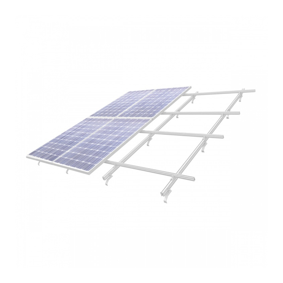
The most common option is to horizontally assemble type e.g. TF50+ carrier rails and arrange solar modules vertically. For this reason, any further mounting procedures describe such an arrangement. Figure 1: View of the IBC TopFix 200 pitched roof mounting system Important! We would like to once again point out that the applicable accident prevention regulations (UVV) must be observed when working on the roof (including VBG 37 construction work, paragraph 12 "Fall protection... - Page 10 We have illustrated the layout of the IBC TopFix 200 mounting system to improve transparency: Figure 2: Fastenings for the IBC TopFix 200 pitched roof mounting system Figure 3: Module fastening of the IBC TopFix 200 pitched roof mounting system...
- Page 11 Figure 4: Layout of the IBC TopFix 200 pitched roof mounting system Description L = (MB + 24 mm) × n + 32 mm Carrier rail length = (MB + 24 mm) × number of modules per row + 32 mm...
-
Page 12: Fitting The Various Mounting Systems
04. Fitting the various mounting systems General dimensioning information The PV system on your roof is subject to considerable forces caused by snow and, most of all, wind. Improper fastening of the PV system, particularly the modules, may cause significant damage to objects as well as personal injury. - Page 13 Fitting the roof hooks In order to comply with warranty conditions (rain-proofing etc.) we recommend having the roof hooks fitted by a roofing firm. Please also take into account the manufacturer's regulations and specifications for the corresponding roofing, in particular with regard to the use of manufacturer accessories for roofing as well as the overview in section 11 containing data on the rafter dimensions required as per EN 1995-1-1.
- Page 14 If the roof hook cannot be fitted as shown above due to the form of the tile or the position of the depression, it is imperative that a roofer is engaged. Changes to roof covering materials (roof tiles, clay tiles, roof panels, cast stone, etc.) may only be made in accordance with the applicable roofing trade regulations and the manufacturer’s guidelines.
- Page 15 Roof hook types Important! The specifications of the general building approval Z-14.4.-661 for steel roof hooks and Z-14.4.-515 for aluminum roof hooks have to be considered. 4.3.1 "Standard S+" roof hook Generally the "Standard" S+" roof hook is used. It is suitable for the most commonly used types of pantiles. Figure 11: "Standard S+"...
- Page 16 4.3.2 "Standard S+ 35 mm" roof hooks Figure 13: roof hook “Standard S+ 35 mm“ parameters value Material Stainless steel 1.4301 S460 yield strength = 460 N/mm² Dimensions base plate (length / width / height) 135/ 70/ 4 mm Dimensions hook (width / height) 30/ 6 mm ∅...
- Page 17 4.3.3 "Mammut S+" roof hooks "Mammut S+" roof hooks are used to ensure the safety of the structure under high snow loads. This roof hook provides improved static characteristics compared with the "Standard S+" roof hook. In certain conditions (e.g. low snow load zone), it may be possible to install "Mammut S+"...
- Page 18 4.3.4 “Mammut SV+” roof hooks For vertical installation of the carrier profile in the 1st layer. Figure 17: “Mammut SV+” roof hook parameters values Material Stainless steel 1.4301 S460 yield strength = 460 N/mm² Dimensions base plate (length / width / height) 157/ 65/ 5 mm Dimensions hook (width / height) 35/ 6 mm...
- Page 19 4.3.5 “Vario S+” roof hooks For horizontal and vertical adjustability at the base plate. Figure 19: “Vario S+” roof hook parameters value Material Stainless steel 1.4301 S460 yield strength = 460 N/mm² Dimensions base plate (length / width / height) 155/ 75/ 5 mm Dimensions hook (width / height) 35/ 6 mm...
- Page 20 4.3.6 “Schiefer S+” roof hooks Special roof hooks designed for the particular roofing tile shape are used for slate tiles. Figure 21: "Schiefer S+" slate tile roof hook parameters value Material Stainless steel 1.4301 S460 yield strength = 460 N/mm² Dimensions base plate (length / width / height) 280/ 30/ 6 mm Dimensions hook (width / height)
- Page 21 4.3.7 “Plain tile” roof hook Plain tiles have a different shape from normal roofing tiles. For this reason, a different roof hook type is used. Figure 23: "Biber S+" plain tile roof hook Figure 24: Depression for “Biber S" parameters value Material Stainless steel 1.4301 S460...
- Page 22 4.3.8 “Alu-Vario S+” roof hooks 4-way adjustable aluminum roof hooks Figure 26: “Alu-Vario S+“ roof hook parameters value Material hook: Alumnium EN AC-42100 (DIN EN 1706) base plate: Alumnium EN AC-43000 (DIN EN 1706) yield strength hook: f = 210 N/mm² base plate: 220 N/mm²...
- Page 23 4.3.9 “Alu-Mammut S+” roof hooks Figure 28: “Alu-Mammut S+” roof hook parameters value Material Alumnium EN AC-42100 (DIN EN 1706) yield strength hook: f = 210 N/mm² Dimensions base plate (length / width 150/ 63,5/ (12) mm / height) Dimensions hook (width / height) 35/ 6-8 mm ∅...
- Page 24 4.3.10 “Alu-Mammut SV+” roof hooks For vertical installation of the carrier profile in the 1st layer. Figure 30: “Alu-Mammut SV+” roof hook parameters value Material Alumnium EN AC-42100 (nach DIN EN 1706) yield strength hook: f = 210 N/mm² Dimensions base plate (length / 181/ 71/ (12) mm width / height) Dimensions hook (width / height)
- Page 25 Observe the edge distances according Figure 121 Select the required screw length according to Figure 32 or using the IBC SOLAR AG PV Manager dimensioning software. It is not required to drill bores before inserting the screws.
- Page 26 Two ASD flat head screws are required to fasten one roof hook. Figure 35: Inserted flat head screws Figure 34: Inserting flat head screws Each roof hook connection must additionally be secured by a ASD countersunk screw to absorb sliding forces at an angle of 60°.
- Page 27 IBC SOLAR AG recommends to test one "Mammut Form S+" on the available roof tiles as there may be manufacturer-specific dimensions despite the designations being identical (e.g. Tegalit prior to 1996).
- Page 28 Step 2: Figure 38: Fastening the batten rail Remove roof tile from the specified area Horizontally move the reinforcing runner (2) horizontally until the slot on the support member (3) covers the hole of the reinforcing rail. Secure the reinforcing runner using one screw (4) (screw may alternatively be fastened from the top).
- Page 29 4.5.2 Fitting "Mammut Form S+" roof hooks on bitumen roofs Legend: (1) Roof hook (2) 4.8×32 mm drilling screw (3) 4.8×60 mm drilling screw Figure 40: "Mammut Form S+ Bitumen" Specify the roof hook position so that the roof hook (1) can be attached to the rafter using screws (3). ...
- Page 30 4.5.3 Fitting "Mammut Form S+" roof hooks on plain tile roofing Figure 41: "Mammut Form S+" plain tile dual roofing Figure 42: Mammut Form S+" plain tile crown roofing Version 17.01, as of: 27-Jun-2017...
- Page 31 4.5.4 Fitting „Mammut Form S+“ roof hook for slate and metal shingle roofs Step 1: Legend: (1) Metal plate (2) Mounting plate (3) Woodscrew 8x140 mm (4) cover cap (5) roof hook (6) Screw nut M6 Figure 43 Insert the metal plate (slte roof only)) ...
- Page 32 Step 3 Figure 45 Cover cap and roof hook Step 4 Figure 46 Roof hook fixing Fix the cover cap (4) and the roof hook (5) at the mountig plate with the M6 nuts (6). (torque 10 Nm) Version 17.01, as of: 27-Jun-2017...
- Page 33 Installation using M12×300 hanger bolts and M10x200 hanger bolts on the timber substructure. Hanger bolts are used on corrugated eternit and trapezoidal sheet metal roofs as well as bitumen roofs to attach the carrier rails. The load bearing roof construction to which the hanger bolt is secured consists of timber purlins or timber rafters.
- Page 34 Cut hanger bolts using an angle grinder if they protrude too far (comply with accident prevention regulations). For stress reasons, the universal connector must always be mounted in the direction of the roof ridge. Figure 49: Correctly fitted hanger bolt with universal connector Important! The stress values for the M12x300 hanger bolt relate to a fixing distance l = 100mm for a use of corrugated eternit panels.
- Page 35 Adapt the required length of the solar fastener to the height of the roof structure. Use IBC SOLAR AG's very own "PV Manager" planning software to ensure you select the right solar fastener. Version 17.01, as of: 27-Jun-2017...
- Page 36 Please note: Comply with the following requirements regarding the roof profile type: The nominal sheet metal profile panel thickness around the fasteners is ≥ 0.4 mm for steel and ≥ 0.5 mm for aluminium. The nominal width of the outer layer of the sandwich element around the fasteners is ≥ 0.4 mm. ...
- Page 37 Mounting plate duo The mounting plate duo is used for fixing with two hanger bolts or two solar fasteners. The two screws are connected through the mounting plate duo. The rooftop connector profile is then fixed on the mounting plate duo. There are two different variants for connecting the profiles.
- Page 38 Mounting with trapezoidal sheet metal clamps 4.9.1 Introduction IBC SOLAR AG trapezoidal sheet metal mounting in combination with the IBC TopFix 200 mounting system is a fast, universal and structurally tested solution for attaching solar modules onto trapezoidal sheet metal roofs.
- Page 39 * The listed tools and auxiliary agents are required exclusively for installation and processing of the trapezoidal sheet metal panels. Information about tools for module and carrier rail mounting is provided in section 1 in these installation instructions. 4.9.3 Dimensioning The mounting system is dimensioned in our very own PV Manager software, taking into account local conditions.
- Page 40 Step 4: Affix the TRAPEZOIDAL CLAMP Note: The heavy-duty adhesive tape can be used from an object and working temperature of 0° C; final adhesion occurs after approx. 72 h at an ambient temperature of 20° C. The higher the temperatures, the faster this process is complete.
- Page 41 Step 6: Insert and align the TF27-T carrier rail Figure 60: Insert the carrier rail Figure 61: Align the carrier rail Figure 62: Close the clamp Figure 63: Mount carrier rail Step 7A: Affix the TRAPEZOIDAL CLAMP to the outer roofing with blind rivets Important: A drill with a diameter of 5.0 mm is mandatory to maintain static properties! ...
- Page 42 Step 7B: Affix the TRAPEZOIDAL CLAMP to the outer roofing with self drilling screws When using the self drilling screws, two screws are placed per TRAPEZOIDAL CLAMP. In this process, make sure you screw carefully to maintain static properties. ...
- Page 43 Now insert the 4.8x15mm blind rivets into the bores and rivet. Figure 71: Rivet transverse securing clamps Step 8B: Insert and affix the transverse securing clamp with self drilling screws The transverse securing clamps are affixed next to the trapezoidal clamp on the left and right with a clearance of approximately 20 mm.
- Page 44 Step 9: If required: Insert butt connector Butt connectors are inserted via the TF27 carrier rail and fixed. Figure 73: Insert butt connectors Figure 74: Joining together the carrier rails The butt connector is either attached using two 4.8x15 mm blind rivets (pre-drilling) or two 5.5x25 mm self drilling screws.
- Page 45 4.9.5 Eco trapezoidal system The Eco trapezoidal system is a pre-assembled, short-rail system to which trapezoidal profiles are riveted or scrwed together. Important: Thermal expansion dictates a thermal separation after 15 modules in one row. Step 1: Dimensioning using "PV Manager" Step 2: Mark the fixing points of the clamp Figure 75: Marking fixing points Step 3: Clean the roofing...
- Page 46 Step 4: Affixing the "Eco trapezoidal system" Figure 76: Removing the protective foil Figure 77: Affixing the "Eco trapezoidal system" Step 5: Distributing the "Eco trapezoidal system" as specified Figure 78: "Eco trapezoidal system" distributed as specified Step 6A: Affix "Eco trapezoidal system" to the outer roofing with blind rivets Important: A drill with a diameter of 5.0 mm is mandatory to maintain static properties!
- Page 47 Figure 80: Inserting blind rivets Figure 81: Riveting using a standard rivet head Step 6A: Affix "Eco trapezoidal system" to the outer roofing with blind rivets When using the self drilling screws, two screws are placed per “clamp base”. In this process, make sure you screw carefully to maintain static properties.
- Page 48 Step 7: Alignment of PV modules Figure 84: Aligning PV modules Version 17.01, as of: 27-Jun-2017...
- Page 49 4.10 Installation of sheet seam clamps Special fastening elements are used to fasten PV modules on standing seam roofs, which are then attached to the carrier rails. The roofing must not be damaged by the load on the installed clamps. For this reason, we recommend having sheet seam clamps fitted by a roofing company.The tightening torque of the sheet seam clamp must be limited in such a way that the sheet metal is not deformed and the thermal expansion of the sheets is not hindered.
-
Page 50: Fitting Carrier Rails
05. Fitting carrier rails Insert the pre-assembled securing screw (M10 connection piece for roof hook profile) through the roof hook slot. Rotate by 90° and insert into the mounting groove of the e.g. TF50+ carrier rail. Connect TF50+ carrier rail to the roof hooks at the required height and tighten the screw. Important: Please ensure all teeth of the type e.g. - Page 51 The ends of the rows must be aligned at an exact right angle (90°) to the bottom rail, as otherwise it will not be possible to align the joints between the modules. Once the carrier rails have been aligned, re-tighten IBC SOLAR AG screws to the corresponding tightening torque and re-check. Version 17.01, as of: 27-Jun-2017...
-
Page 52: Fitting Pv Modules
06. Fitting PV modules The middle and outer clamp are delivered pre- assembled. The middle clamp G3 covers a clamping area of 30-50 mm. However the outer clamp G3 must be ordered for G3 Middle and outside clamp each module height. The middle clamp G4 covers a clamping area of 33-46 mm. - Page 53 The middle and outside clamps can be inserted into the carrier rail directly from the top, into the position where they are required. Figure 92 Inserting middle clamps G3 The middle clamp G4 is swiveled into the carrier rail, where it is needed Figure 93 Inserting middle clamps G4 Important! The slot nut of the G4 clamp must be aligned as shown in the Figure 93 and must not be installed twisted.
- Page 54 The adaptor EC is clamped by the given frame height with the middle clamp G4 and substitutes thus the outer clamp. Figure 94 EC adapter with middle clamp G4 Figure 95 EC adapter frame hights Subsequently place the first module onto both carrier rails, loosely tighten it to the outside clamps respectively the middle clamp including EC adapter and align with the row of roof tiles.
-
Page 55: Fitting Cable Clips
The cable clips are used to fix the module connector cables and prevent sagging of the cable. The clips can be clamped to the carrier rails of the mounting system TopFix 200 or to the photovoltaic module frames without any tools. Figure 96 shows the attachment of the cable clips 0° at the PV-module frame. In Figure 97 the cable clip is shown schematically 90°... -
Page 56: Fitting The Two-Layer Carrier System
08. Fitting the two-layer carrier system 8.1 General information In contrast to single-layer carrier rails, this method additionally employs carrier rails as so-called roof hook connecting rails before the actual carrier rail is fitted. 8.2 Type e.g. TF50+ roof hook connecting rails Figure 98: Roof hook connecting rails and carrier rails as a unit Description Carrier rail length =... - Page 57 Roof hook Two-layer connector Max. 400mm As per PV Manager Max. ¼ of the module height (please observe module manufacturer specifications) Dimensioning: Two-layer systems are dimensioned in the same way as single-layer systems. However, the following special features must be taken into account: ...
-
Page 58: Delta Support
Figure 100: Delta support 9.1 General information Delta supports enable to use the IBC TopFix 200 mounting system as an elevated mounting system and achieve optimum module inclination. Delta supports are available with single as well as continuous base rails. Inclination angles between 10°... - Page 59 9.2 Assembly Assembling single Delta supports Figure 103: Assembling Delta supports using single base rails Delta supports with single base rails are supplied as complete, folded and pre-assembled units, including three M8×50 hex screws with self-locking nut and tube sleeves. Secure the unfolded support using screw connections.
- Page 60 9.3 Connection to the roof We offer the following connection types to connect Delta supports, depending on the available roof seal and roof substructure: Fixation by hanger bolt Fixation by universal connector Fixation by additional weight (e.g. positioning walkways, etc.) ...
- Page 61 Figure 108: Two--layer fixation (two-layer connector) Version 17.01, as of: 27-Jun-2017...
- Page 62 9.4 Mounting modules Modules can be mounted either horizontally or vertically using Delta supports. Modules up to a module size of 1.7 m can are suitable for vertical mounting. Vertical module – clamps on the long sides In this case, Delta supports are connected using two carrier rails (TF50+/TF50m/TF60).
-
Page 63: Ibc Framefix Module Frame Reinforcements
A high degree of snow loads on vertically mounted modules may deform the frame and hence render the module unusable. IBC FrameFix counteracts this and reinforces the frame from the rear. The structure is not visible and it does affect the mounting system. - Page 64 Figure 113: Corner bracket Figure 114: Tensioning piece Assembling adapter Figure 116 Disconnect the cable from the tensioning piece Figure 115 Tensioning piece an adapter Figure 118 Adapter mounted Figure 117 Insert the adapter under the cable Version 17.01, as of: 27-Jun-2017...
-
Page 65: Bill Of Materials
11. Bill of materials Illustration Item no.: Item 6800100022 Support rail TF50+ (uncut length L = 5200 mm) 6800100023 Support rail TF50+ aluminium (uncut length L = 3100 mm) 6800100027 Support rail TF50+ (uncut length L = 2100 mm) 6800100033 Support rail TF50+ black (uncut length L = 5200 mm) 6800100019... - Page 66 Illustration Item no.: Item IBC TopFix 200 middle clamp G3 6700400125 Middle Clamp G3 30-50mm 6700400126 Middle Clamp G3 30-50mm, black IBC TopFix 200 outside clamp G3 6700400127 End clamp G3 31 mm 6700400128 End clamp G3 31 mm black...
- Page 67 Illustration Item no.: Item 6700500005 Laminate middle clamp G2 (for module thickness from 6.8 to 8 6700500006 Laminate end clamp G2 (for module thickness from 6.8 to 8 6700400144 Middle clamp G4 33-46mm 6700400145 Middle clamp G4 33-46mm black 6700400161 EC adapter 33-46mm 6700400162 EC adapter 33-46mm black...
- Page 68 Illustration Item no.: Item 6700100027 "Mammut S+" roof hook 6700100028 "Mammut SV+" roof hook 6700100029 "Vario S+" roof hook 6700100030 "Biber S+" plain tile roof hook 6700100031 "Schiefer S+" slate tile roof hook Version 17.01, as of: 27-Jun-2017...
- Page 69 Illustration Item no.: Item 6700700022- "Mammut Form S+" roof hook 6700700040 Includes: 1x roof hook with sheet metal tile & 1x reinforcing runner 3x 4.2x32 mm drilling screw (tallow- 6700700042- drop screw, galvanised, AW 20) 1x 5.0x120 mm drilling screw (self- 6700700097 tapping, countersunk screw, galvanised, AW 20 type 2)
- Page 70 Illustration Item no.: Item “Alu-Mammut S+” roof hook 6700100038 “Alu-Mammut SV+” roof hook 6700100039 6700200036 Trapezoidal sheet clamp Without accessories 6700200037 ECO trapezoidal system, 340 mm Without accessories 6700200038 ECO trapezoidal system, 420 mm Without accessories 6700200041 Hanger bolt M12x300 A2 SW9 Including 1x EPDM seal 3x M12 A2 self-locking nuts...
- Page 71 Illustration Item no.: Item 6700200045 Hanger bolt M12x250 A2 SW9 Including 1x EPDM seal 3x M12 A2 self-locking nuts completely pre-assembled 6700200026 Hanger bolt M10x200 A2 SW7 Including 1x EPDM seal 3x M10 A2 self-locking nuts completely pre-assembled 6700200018 Solar fastener 8/M10x80/50 Including bell-type seal and nuts,...
- Page 72 Illustration Item no.: Item 6700300050 Mounting plate duo TopFix 200 Including screws + universal connector 6700300051 Mounting plate duo TopFix 200 Including Connecting Connection Piece M10 6700200011 Standing Seam Clamp Including universal connector 6700200027 Original Kalzip® clamp Including universal connector...
- Page 73 Illustration Item no.: Item Delta support, single Pre-assembled 6100300024 Delta support, 10°, single 6100300025 Delta support, 15°, single 6100300026 Delta support, 20°, single 6100300027 Delta support, 25°, single 6100300028 Delta support, 30°, single 6100300029 Delta support, 35°, single 6100300030 Delta support, 40°, single 6100300031 Delta support, 45°, single Delta support, continuous...
- Page 74 Illustration Item no.: Item 6700300046 Butt connector TF50+ / TF50-m Including 2x M10x25 A2 T-head screws 2x DIN 6923 M10 A4 locking nuts -> completely pre-assembled 6700300044 Butt connector TF60 Including 2x M10x25 A2 T-head screws 2x DIN 6923 M10 A4 locking nuts 6700300058 Butt connector TF27-T Without accessories...
- Page 75 Illustration Item no.: Item 6700300041 Rail end cap for TF50+ and TF50m 6700300061 Rail end cap black for TF50+ and TF50m 6700300045 Rail end cap for TF60 6900300007 Flange Head Screw 6x100 A2 6900300008 Flange Head Screw 8 x 100 A2 6900300010 Flange Head Screw 8 x 140 A2 6900300011...
- Page 76 Illustration Item no.: Item 6908300003 Blind Rivet 4.8x15 PU 100 6900600011 Self-Drilling-Screw 5.5x25 PU 100 6700300032 Connection Piece M10 For roof hooks 6700300053 Connection Piece M8 For roof hooks 6700300033 Universal Connection Piece 6700200013 Clamp for equipotential bonding 6700300042 FrameFix, 60 cell unit, 6" 6700300043 FrameFix, 60 cell unit, 6", black 6700300049...
-
Page 77: Appendix
12.1 Notes on IBC TopFix 200 Tightening torques for screw connections The tightening torques for the screw connections used in the IBC TopFix200 mounting system must be dimensioned in accordance with DIN ISO 3506, to document and archive for 10 years. Due to the difficulty in determining the outdoor friction coefficients, dimensioning in accordance with DIN ISO 3506 can prove difficult. -
Page 78: Version 17.01, As Of: 27-Jun
Required rafter and purlin dimensions Comply with the following minimum dimensions for rafters and purlins as per EN 1995-1-1. Figure 121: Minimum distance and required timber component dimensions The minimum rafter/purlin height must be 100 mm. The minimum distance between fastened flat head screws and the edges of rafters and purlins must be three times the flat head screw diameter. - Page 79 12.2 Weights/installation times for pitched roof installations Weight per m² of module Weight per kWp surface 10 … 17 kg/m² 130 … 300 kg/kWp Thin-film solar modules 11 … 21 kg/m² 70 … 175 kg/kWp Crystalline solar modules *2.4 … 5 kg/m² *18 …...
- Page 80 12.3 Notes on maintenance The IBC TopFix 200 mounting system is largely maintenance-free thanks to the materials used. In addition to the electrical inspections prescribed for the entire PV system, we recommend inspections of the PV generator every two years, considering the following points.
- Page 81 IBC SOLAR AG Am Hochgericht 10 D-96231 Bad Staffelstein Phone +49 (0) 9573-92 24 0 Fax +49 (0) 9573-92 24 111 info@ibc-solar.de www.ibc-solar.com Version 17.01, as of: 27-Jun-2017...
Need help?
Do you have a question about the TopFix 200 and is the answer not in the manual?
Questions and answers