KEB Combivert F5 Installation Manual
Hide thumbs
Also See for Combivert F5:
- Applications manual (378 pages) ,
- Reference manual (349 pages) ,
- Instruction manual (196 pages)

Related Manuals for KEB Combivert F5


Summary of Contents for KEB Combivert F5
- Page 1 C O M B I V E R T GB Installation Manual F5 with Safety Function „STO“ Control Circuit Original Manual Mat.No. Rev. 00F5NES-K000...
-
Page 3: Table Of Contents
Table of Contents Preface ......................5 General ..........................5 Validity and liability ......................5 Copyright ..........................6 1.4 Specified application ......................6 Product description ......................6 Control ......................8 Features of the control ......................8 Overview ..........................8 2.2.1 LED1 ............................9 2.2.2 HSP5 interface X4A ....................... - Page 4 Table of Contents GB - 4...
-
Page 5: Preface
Preface Preface General First we would like to welcome you as a customer of the company Karl E. Brinkmann GmbH and congratulation to the purchase of this product. You have decided for a product on highest technical niveau. The described hard- and software are developments of the Karl E. Brinkmann GmbH. The enclosed documents correspond to conditions valid at printing. Misprint, mistakes and techni- cal changes reserved. -
Page 6: Copyright
If single regulations should be or become void, invalid or impracticable, the effectivity of all other regulations or agreements is not affected. Copyright The customer may use the instruction manual as well as further documents or parts from it for internal purposes. Copyrights are with KEB and remain valid in its entirety. Specified application The COMBIVERT F5 serves exclusively for the control and regulation of three-phase motors. The operation of other electric consumers is prohibited and can lead to the destruction of the unit. Inverter are components designed for inclusion in electrical installations or machinery. - Page 7 Preface COMBIVERT F5 inverter with integrated safety technology correspond to the following nu- merical code: Inverter Control SW Operating mode Control HW used (ud.02) APPLICATION xxF5Kxx-xxxx with encoder MULTI interface 1KF5x30-0009 up to housing size E APPLICATION xxF5Kxx-xx0x without encod- GENERAL 2KF5x30-0008 from housing size G er interface xxF5Lxx-xxxx ASCL MULTI xxF5Pxx-xxxx SERVO The certification of controllers with safety tech-...
-
Page 8: Control
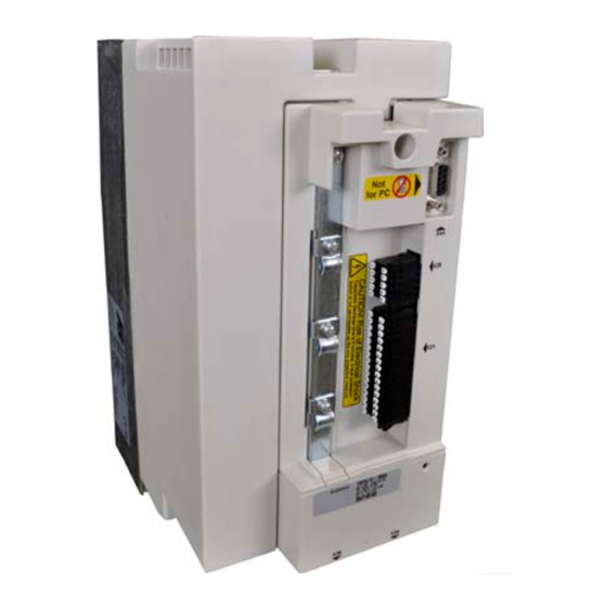
Control Control Features of the control The control provides the following analog and digital functions: • Hardware allocation of digital and analog inputs and outputs. • HSP5 interface for the connection with an operator or via special cable (00F50C0-0010) with a PC • Hardware of the control circuit „safety separated“ according to EN 61800-5-1 (base TN- C/-S mains) • Operation and diagnosis via operator • Safety function STO (two channel torque off) Overview Control 2KF5xxx-xxxx from G housing Control 1KF5xxx-xxxx in D & E housing X2A Control terminal strip HSP5 diagnostic interface X2B Terminal block safety function... -
Page 9: Led1
/ disconnecting the operator (open control release terminal). When starting the inverter, it is started always with the last stored values or factory setting. A special HSP5 cable (part number 00.F5.0C0-0010) is required for the operation of the KEB COMBIVERT without operator. This cable is connected between HSP5 interface X4A and serial RS232 PC interface (COM1 or COM2). Operation occurs via the program COMBIVIS. The HSP5 service cable has an integrated level converter. The connection of a serial standard cable would destroy the PC interface. -
Page 10: Connection Of The Control
0.75 mm / 19 12 mm 14 mm 1.00 mm / 18 12 mm 15 mm KEB generally recommends the use of wire-end ferrules in industrial Info environments. Cross-section / AWG Stripping length 0.14 1.5mm2 , 25 16 10 mm Stranded wire (rigidly and flexibly) •... -
Page 11: Assignment Of The Terminal Strip X2A
Control Front view Side view a) Pusher b) Connecting wire hole Assignment of the terminal strip X2A Name Description Specifications Digital mass; reference potential for digital inputs/outputs, U and U U=24 VDC +20 %/-15 % Input external voltage supply =1 A like pin 1 U=24 VDC ±25 % Voltage output for the control of the digital inputs (Pin 4+32)=100 mA Programmable 8 digital inputs according to IEC61131-2 type 1 digital inputs „0“ = -3…5 VDC (Assignment ex factory „1“ = 15…30 VDC see chapter 2.4.1) Scan time ≤ 1 ms further on next side GB - 11... - Page 12 Control Name Description Specifications 2 short-circuit proof digital 24 V outputs Programmable specified according to IEC61131-2 digital outputs Imax = 100mA per output (Assignment ex factory Switching of inductive load (without free-wheel- see chapter 2.4.2) ing path) up to 300mJ maximum switching frequency = 1kHz like pin 1 Reference voltage for 10 VDC +5 %; I = 4 mA setpoint potentiometer AN1- 0…±10 Vdc (R =55 kΩ) Programmable 0…±20 mA (R =250 Ω) AN1+ analog inputs 4…20 mA (R =250 Ω) (Assignment ex factory...
-
Page 13: Connection Of The Digital Inputs
Control 2.4.1 Connection of the digital inputs Connection of the digital inputs with internal voltage supply with external voltage supply 6 8 10 6 8 10 Factory setting of the digital inputs Operating GENERAL MULTI/SERVO mode Input Reset Reset Control release Control release / reset Direction of rotation reverse Limit switch left... -
Page 14: Connection Of The Analog Inputs
Control 101214 9 11 13 Factory setting of the digital outputs Operating mode GENERAL MULTI/SERVO Input Ready signal Ready signal Switch at actual value=setpoint Switch at actual value=setpoint value value 2.4.3 Connection of the analog inputs Examples for the connection of the analog setpoint input R = 0…3/5/10kΩ... -
Page 15: Connection Of The Analog Outputs
Control 2.4.4 Connection of the analog outputs Connection of the analog outputs 0…10Vdc 0…10Vdc 10mA 10mA max= max= 2224 Factory setting of the analog outputs Operating mode GENERAL MULTI/SERVO Input Output frequency 0…100 Hz Speed actual value 0…3000 rpm Apparent current 0…2•Iout Apparent current 0…2•Iout 2.4.5 Connection of the relay outputs Connection of the relay outputs Specification: U = max. 30 Vdc... -
Page 16: Assignment Of The Terminal Block X2B
Control Assignment of the terminal block X2B Name STO1+ STO1+ Input STO channel 1 STO1- STO1- STO2+ STO2+ Input STO channel 2 STO2- STO2- STO-OUT Output STO STO-OUT The individual channels are designed potential-free, so 24V and 0 V can be connected. The inputs are designed by way that safety switchgear units with test pulses (OSSD signals) can be connected. The signals are not evaluated, they are only filtered. The OSSD test interval is limited to 10 ms. The output STO-OUT at terminal 9/10 is switched against the mass of the control. 2.5.1 inputs 2.5.1.1 Specification of the STO inputs Status 0 Status 1 STO inputs UL [V] IL [mA] UH [V]... -
Page 17: Safety Function Sto
Safety Function STO Safety Function STO Uncontrolled start of the drive is possible by improper instal- lation of the safety technology. This may cause death, serious Only bodily injuries or substantial damage to property. Qualified Therefore the safety function may only be installed and put into Staff operation by qualified personnel which are trained in safety tech- nology. The COMBIVERT F5 with safety function must not be started until it is determined that the installation complies with 2006/42/ EC (machine directive) as well as the EMC directive (2004/108/ EC)(note EN60204). -
Page 18: Emergency Stop According En 60204
Safety Function STO Regular electromechanical equipment are liable to abrasion. Loss of these equipment occurs by using the STO function and the maintenance costs are reduced. Characteristic data for „Safe torque off“ • Power supply for the rotation direction of the motor is interrupted (free-wheeling motor) • Used when monitoring of standstill is not necessary • Unintentional starting of the motor is prevented • No galvanic isolation of the motor from the dc link circuit What is realized by the STO function related to EN 60204 -1 ? • Emergency stop can be realized by the STO function, since the mains voltage may re- main effective. -
Page 19: Classification Of Sto According Iec 61508
Safety Function STO Calculation of the jerk: 180° Rotation angle of the jerk W [°] = ––––––––––––––––––––––––––––––––– Pole-pair number p • gear reduction ratio g This behaviour can occur either by a short circuit of the IGBTs or by interconnection (also short circuit) of the control drivers. The error should be regarded as critical, if the drive re- mains in STO status. Classification of STO according IEC 61508 2.6 • 10 2.3 • 10 on demand Proof-Test-Interval T 20 years For SIL classification in connection with the applications consider the failure rates of the ex- ternal switch devices for final evaluation. -
Page 20: Functional Description
Safety Function STO Functional Description The COMBIVERT with integrated safety function meets the following function according to IEC 61800-5-2: • „Safe torque off" (STO) The safety-related disconnection according to STO is reached by a two-cannel opto-coupler blockage. The supply of the opto-couplers, which are responsible for the commutation of the connected drive occurs via transformation coupling of the input voltage. This ensures at input voltage loss that no supply of the opto-couplers is possible. If the opto-couplers are not longer supplied, no IGBT can be controlled and thus no energy can be supplied to the drive. The two channels are reached by way that input STO1 prevents the voltage supply (VTRO) of the upper opto-couplers of the inverter bridge and input STO2 the lower opto-couplers (VTRU). -
Page 21: Wiring Examples
Safety Function STO Wiring Examples 3.6.1 Direct switching off with emergency stop switch Diagnosis Control circuit 24Vdc Safety module Terminal strip X2B 1 - STO1+ 2 - STO1+ 3 - STO1- 4 - STO1- 5 - STO2+ 6 - STO2+ 7 - STO2- 8 - STO2- 9 - STO-OUT... -
Page 22: Direct Switching Off With Emergency Stop Switch And Monitoring Of The Wiring
Safety Function STO 3.6.2 Direct switching off with emergency stop switch and monitoring of the wiring Diagnosis Control circuit 24Vdc Safety module Terminal strip X2B 1 - STO1+ 2 - STO1+ 3 - STO1- 4 - STO1- 5 - STO2+ 6 - STO2+ 7 - STO2- 8 - STO2-... -
Page 23: Direct Switching Off By Safety Module With Test Pulses
Safety Function STO 3.6.3 Direct switching off by safety module with test pulses Diagnosis Control circuit open closed Safety module Terminal strip X2B Safety device 1 - STO1+ Receipt 2 - STO1+ 3 - STO1- 4 - STO1- 5 - STO2+ 6 - STO2+ 7 - STO2- 8 - STO2-... -
Page 24: Wiring Ss1
Safety Function STO 3.6.4 Wiring SS1 At tripping SS1 (Safe Stop 1) the drive is only disconnected from supply when it has reached a standstill [IEC 61800-5-2]. The stop mode is not directly requested, but the maximum time until reaching the standstill is estimated. This period is loaded in a safe time relay, which dis- connects the drive finally from supply. Diagnosis Control circuit open closed Safety module Terminal strip X2B Safety device Safety device 1 - STO1+ 2 - STO1+ Receipt 3 - STO1- 4 - STO1- X2A.12 (I3) 5 - STO2+ 6 - STO2+ 7 - STO2- 8 - STO2-... - Page 25 Safety Function STO The following adjustments must be done in COMBIVERT for the function „drive stop“: Parameter Adjustment Pn.03 „Reaction to error prog. input“ 1: quick stopping; modulation off; no auto- matic restart Function: If the selected input becomes active, the drive decelerates with the quick stopping function. The drive changes into status 31 „Error! External input", when PN.68 is activated (<> 0) and the adjusted time has expired. GB - 25...
-
Page 26: Certification
Annex Certification Annex to the declaration of conformity Annex to the declaration of conformity EC for systems with functional safety: Product designation: Inverter - type series xxF5Kxx-xxxx xxF5Lxx-xxxx xxF5Pxx-xxxx Herewith we declare that the safety module described above corresponds with all relevant regulations of the machinery safety directive 2006/42/EC. - Page 27 Annex The conformity was confirmed by the TÜV Rheinland with the EC type examination 01/205/5141/11. The number and address of the indicated constitution: NB 0035 TÜV Rheinland Industrie Service GmbH Alboinstr. 56, 12103 Berlin Germany Tel.: +49 30 7562-1557 Fax: +49 30 7562-1370 E-Mail: tuvat@de.tuv.com GB - 27...
-
Page 28: Revision History
Revision history Revision history Revision Date Description Rev.1D 2011-02 First published version Rev.1E 2011-08 Correction: Assignment of the terminal strip; Resolution: 11 Bit + sign Rev.1F 2012-01 Inscribed certification number; Typing error chapter 3.3.6 in german corrected Rev.1G 2012-09 Correction input external voltage supply Rev.1H 2013-03 FS marking inserted; Terminal blocks changed to new standard; Switching condition output STO corrected Rev.1J 2013-09 New picture on title, strip control wires Rev.1K 2014-07 Control categorie to categorie and assembly of wire-end ferrule changed GB - 28... - Page 29 Notices GB - 29...
- Page 30 KEB Antriebstechnik Herenveld 2 • B-9500 Geraadsbergen KEB Italia S.r.l. fon: +32 5443 7860 • fax: +32 5443 7898 Via Newton, 2 • I-20019 Settimo Milanese (Milano) mail: vb.belgien@keb.de fon: +39 02 3353531 • fax: +39 02 33500790 net: www.keb.de • mail: kebitalia@keb.it KEB Power Transmission Technology (Shanghai) Co.,Ltd. No. 435 Qianpu Road, Chedun Town, Songjiang District, KEB Japan Ltd. CHN-Shanghai 201611, P.R. China 15–16, 2–Chome, Takanawa Minato-ku fon: +86 21 37746688 • fax: +86 21 37746600 J-Tokyo 108-0074 net: www.keb.de • mail: info@keb.cn fon: +81 33 445-8515 • fax: +81 33 445-8215 mail: info@keb.jp KEB Antriebstechnik Austria GmbH KEB Korea Seoul Organizační složka...
Need help?
Do you have a question about the Combivert F5 and is the answer not in the manual?
Questions and answers