
Related Manuals for Stanford Research Systems SIM983


Summary of Contents for Stanford Research Systems SIM983
- Page 1 Operation and Service Manual Scaling Amplifier SIM983 Stanford Research Systems Revision 2.2 August 28, 2006...
- Page 2 (1) year from the date of shipment. Service For warranty service or repair, this product must be returned to a Stanford Research Systems authorized service facility. Contact Stanford Research Systems or an authorized representative before returning this product for repair.
-
Page 3: Table Of Contents
Contents General Information Safety and Preparation for Use ....Symbols ......Notation . - Page 4 Contents A Index A – 1 SIM983 Scaling Amplifier...
-
Page 5: General Information
Do not install substitute parts or perform unauthorized modifications to this instrument. The SIM983 is a single-wide module designed to be used inside the SIM900 Mainframe. Do not turn on the power to the mainframe or apply voltage input to the module until the module is completely... -
Page 6: Symbols
General Information Symbols you may Find on SRS Products Symbol Description Alternating current Caution - risk of electric shock Frame or chassis terminal Caution - refer to accompanying documents Earth (ground) terminal Battery Fuse On (supply) Off (supply) SIM983 Scaling Amplifier... -
Page 7: Notation
Special ASCII characters are set as CR . Remote command examples will all be set in monospaced font. In these examples, data sent by the host computer to the SIM983 are set as straight teletype font, while responses received by the host computer from the SIM983 are set as slanted teletype font. -
Page 8: Specifications
THD, 1 kHz Output Voltage [1] 10 0 10 0 Maximum current Short circuit duration Indefinite Resistance Terminals Grounded BNC, front [5] and rear [9] Operating Temperature [10] Power V DC Supply current, 5 V 15 V SIM983 Scaling Amplifier... - Page 9 [9] Tyco 227169–4 or similar. [10] Non-condensing. General characteristics Interface Serial (RS–232) through SIM interface Connectors BNC (2 front [5], 1 rear [9]); DB–15 (male) SIM interface Weight 1.5 lbs Dimensions 1 5 W 3 6 H 7 0 D SIM983 Scaling Amplifier...
- Page 10 General Information SIM983 Scaling Amplifier...
-
Page 11: Getting Started
1 Getting Started This chapter gives you the necessary information to get started quickly with your SIM983 Scaling Amplifier. In This Chapter 1.1 Introduction to the Instrument ... . 1 – 2 1.1.1... -
Page 12: Introduction To The Instrument
SIM900 Mainframe, using RS–232 or GPIB. The digital control circuitry in the SIM983 is designed with a special clock-stopping architecture. The microcontroller is turned on only when the polarity, gain, or o set are being changed, during remote communications, or when an overload condition occurs. -
Page 13: Front-Panel Operation
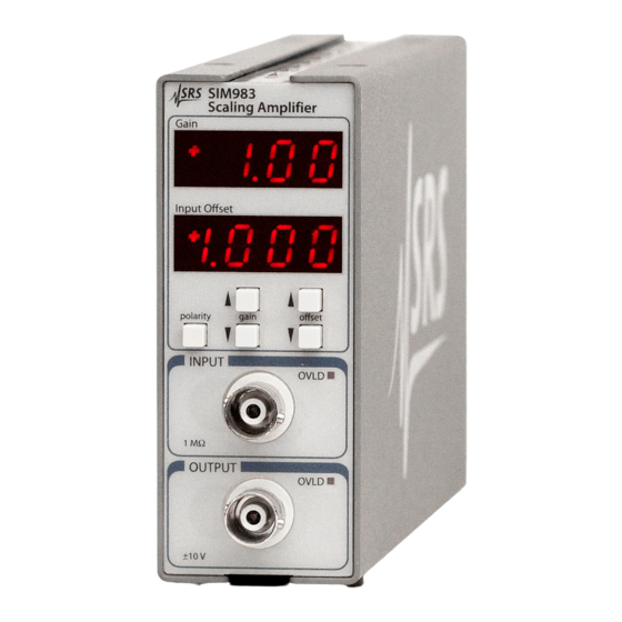
1.2 Front-Panel Operation 1 – 3 1.1.1 Front and rear panels Figure 1.2: The SIM983 front and rear panels. 1.2 Front-Panel Operation 1.2.1 Polarity The polarity is the sign of the gain. It is indicated on the upper display of the front panel. To change the polarity, press the [polarity] button once. -
Page 14: O Set
There are two overload indicators, one OVLD LED in the IN- PUT block and one OVLD LED in the OUTPUT block of the front panel. The overload signal can also be asserted on the STATUS pin. See Section 3.5. SIM983 Scaling Amplifier... -
Page 15: Connections
1.3 Connections For a discussion of the front and rear BNC connections, see Sec- tion 2.1. The SIM interface connector is discussed in Section 1.6.1. SIM983 Scaling Amplifier... -
Page 16: Power-On
The power-on configuration of the remote interface is detailed in Section 3.3.1. 1.5 Restoring the Default Configuration The default configuration of the SIM983 is G 1 00 V 0 000 V and bandwidth 0 (see Section 2.3.1). This configuration is reached from the remote interface by issuing the *RST command. -
Page 17: Sim Interface
SIM900 Mainframe via this connection, either through one of the internal mainframe slots or the remote cable interface. It is also possible to operate the SIM983 directly, without using the SIM900 Mainframe. This section provides details on the interface. - Page 18 RS–232 serial port of a personal computer. Connect RXD from the SIM983 directly to RD on the PC, TXD directly to TD, and similarly RTS RTS and CTS CTS. In other words, a null-modem- style cable is not needed.
- Page 19 1.6.2.2 Serial settings The initial serial port settings at power-on are: baud rate 9600, 8 bits, no parity, 1 stop bit, and no flow control. The baud rate of the SIM983 cannot be changed. Flow control is not implemented in the SIM983.
- Page 20 1 – 10 Getting Started SIM983 Scaling Amplifier...
-
Page 21: Description Of Operation
2 Description of Operation This chapter provides a number of additional details of the operation of the SIM983. In This Chapter 2.1 Signal Connections and Grounding ..2 – 2 2.1.1 Output drive ....2 – 2 2.1.2... -
Page 22: Signal Connections And Grounding
2.1.2 Grounds Both the input and the output of the SIM983 are referenced to ground. To maintain the DC accuracy of the instrument, there are two sepa- rate ground references. Ground 1 (Pin 1 of the SIM interface connec-... -
Page 23: Ac Characteristics
AC signal that can be output; for a sine-wave output at a fre- quency f the maximum peak-peak voltage is V SR ( f ) The SIM983 is designed to be able to output a full-range sine wave at 1 MHz. SIM983 Scaling Amplifier... -
Page 24: Clock Stopping
If the output or an intermediate stage of the amplifier is driven beyond the limits in the table on Page vi, large-signal behavior is not guaranteed. 2.4 Clock Stopping The microprocessor clock of the SIM983 stops if the module is idle, “freezing” the digital circuitry. The following actions “wake up” the clock: 1. -
Page 25: Remote Operation
3 Remote Operation This chapter describes operating the SIM983 over the serial interface. In This Chapter 3.1 Index of Common Commands ... . 3 – 2 Alphabetic List of Commands ... . 3 – 4 Introduction . -
Page 26: Index Of Common Commands
3 – 13 Overload Status Enable PSTA(?) z 3 – 13 Pulse STATUS Mode LBTN? 3 – 13 Last Button OVLD? 3 – 14 Overload Interface *RST 3 – 14 Reset *IDN? 3 – 15 Identify *TST? 3 – 15 Self Test SIM983 Scaling Amplifier... - Page 27 3 – 16 Execution Error LCME? 3 – 16 Command Error LDDE? 3 – 17 Device Error TOKN(?) z 3 – 17 Token Mode TERM(?) z 3 – 17 Response Termination Serial Communications PARI(?) z 3 – 18 Parity SIM983 Scaling Amplifier...
-
Page 28: Alphabetic List Of Commands
3 – 17 Device Error LEXE? 3 – 16 Execution Error OFST(?) f 3 – 10 O set OLSE(?) [i,] j 3 – 13 Overload Status Enable OLSR? [i] 3 – 13 Overload Status OVLD? 3 – 14 Overload SIM983 Scaling Amplifier... - Page 29 3.2 Alphabetic List of Commands 3 – 5 PARI(?) z 3 – 18 Parity PSTA(?) z 3 – 13 Pulse STATUS Mode TERM(?) z 3 – 17 Response Termination TOKN(?) z 3 – 17 Token Mode SIM983 Scaling Amplifier...
-
Page 30: Introduction
3.3.2 Buffers The SIM983 stores incoming bytes from the host interface in a 64- byte input bu er. Characters accumulate in the input bu er until a command terminator (either CR or LF ) is received, at which point the message is parsed and executed. -
Page 31: Commands
CR LF , the following two commands are equivalent: TERM CRLF —or— TERM 3 For queries that return token values, the return format (keyword or integer) is specified with the TOKN command. SIM983 Scaling Amplifier... -
Page 32: Notation
In these examples, all data sent by the host computer to the SIM983 are set as straight teletype font, while responses received by the host computer from the SIM983 are set as slanted teletype font. The usage examples vary with respect to set query, optional parame- ters, and token formats. -
Page 33: General Commands
CESE(?) [i,] {j} - Communications Error Status Enable. OLSR? - Query Overload Status register. OLSE(?) [i,] {j} - Overload Status Enable. PSTA(?) {z} - Pulse Status or change its level. LBTN? - Which button last pressed? OVLD? - Input or output currently overloaded? SIM983 Scaling Amplifier... -
Page 34: Configuration Commands
Set (query) the SIM983 keep-awake mode to z (OFF 0, ON 1) . Ordinarily, the clock oscillator for the SIM983 microcontroller is held in a stopped state, and only enabled during processing of events (Section 2.4). Setting AWAK ON forces the clock to stay running, and is useful only for diagnostic purposes. -
Page 35: Calibration Commands
3.4.6 Calibration commands ACAL Autocalibration Perform a self-calibration (Section 2.2). Make sure to disconnect all inputs and outputs to the SIM983, and to set the output to zero. Remote commands are not processed until ACAL is complete. Example: ACAL LDDE? checks for success of an autocalibration. - Page 36 Set (query) the Standard Event Status Enable register [Bit i] to j . Example: *ESE 6,1 ESE? CESR? [i] Communication Error Status Query the Communication Error Status Register [Bit i]. Upon executing a CESR? query, the returned bit(s) of the CESR reg- ister are cleared. Example: CESR? SIM983 Scaling Amplifier...
- Page 37 [polarity] [gain ] [gain ] [o set ] [o set ] Both [gain ] and [gain ] (reset gain) Both [o set ] and [o set ] (reset o set) One of [gain ] and [polarity] (autocalibrate) SIM983 Scaling Amplifier...
-
Page 38: Interface Commands
The Interface commands provide control over the interface between the SIM983 and the host computer. *RST Reset Reset the SIM983 to its default configuration. *RST sets the following: Clock oscillator to stop during idle time (AWAK OFF). Gain to 1 00 O set to 0.000 V. - Page 39 #.### is the firmware revision level. Example: *IDN? Stanford Research Systems,SIM983,s/n004900,ver2.0 *TST? Self Test There is no internal self-test in the SIM983 after the power-on, so this query always returns 0. Example: *TST? *OPC(?) Operation Complete Sets the OPC flag in the ESR register.
- Page 40 Missing parameter(s) Extra parameter(s) Null parameter(s) Parameter bu er overflow Bad floating point Bad integer Bad integer token Bad token value Unknown token Example: *IDN LCME? The error (4, ”Illegal set”) is due to the missing “?”. SIM983 Scaling Amplifier...
-
Page 41: Serial Communication Commands
Set (query) the token query mode to z (OFF 0, ON 1) . If TOKN ON is set, then queries to the SIM983 that return tokens will return a text keyword; otherwise they return a decimal integer value. Thus, the only possible responses to the TOKN? query are ON and 0. - Page 42 3 – 18 Remote Operation PARI(?) z Parity Set (query) the parity to z (NONE 0, ODD 1, EVEN 2, MARK 3, SPACE 4) . The value in boldface is the power-on value. Example: TOKN ON; PARI? EVEN SIM983 Scaling Amplifier...
-
Page 43: Status Model
OLSE Figure 3.1: Status register model for the SIM983 Scaling Amplifier. There are two categories of registers in the SIM983 status model: Event Registers : These read-only registers record the occurrence of defined events. If the event occurs, the corresponding bit is set to 1. -
Page 44: Status Byte (Sb)
At power-on, all status registers are cleared. 3.5.1 Status Byte (SB) The Status Byte is the top-level summary of the SIM983 status model. When masked by the Service Request Enable register, a bit set in the Status Byte causes the STATUS signal to be asserted on the rear- panel SIM interface connector. -
Page 45: Standard Event Status Enable (Ese)
flags is set by the corresponding event, and cleared only by reading the register or with the *CLS command. Reading a single bit (with the CESR? i query) clears only Bit i. Weight Flag PARITY FRAME NOISE HWOVRN RTSH CTSH DCAS SIM983 Scaling Amplifier... -
Page 46: Communication Error Status Enable (Cese)
RTSH : RTS Holdo Event. Unused in the SIM983. CTSH : CTS Holdo Event. Unused in the SIM983. DCAS : Device Clear. Indicates that the SIM983 received the Device Clear signal (an RS–232 break ). Clears the input bu er and the output queue, and resets the command parser. -
Page 47: Overload Status Enable (Olse)
The OLSE acts as a bitwise AND with the OLSR register to produce the single-bit OLSB message in the Status Byte Register (SB). The register can be set and queried with the OLSE(?) command. At power-on, this register is cleared. SIM983 Scaling Amplifier... - Page 48 3 – 24 Remote Operation SIM983 Scaling Amplifier...
-
Page 49: Performance Verification
4 Performance Verification This chapter describes the tests necessary to verify the SIM983 is operating correctly and within specified calibration. In This Chapter 4.1 Verifying the DC Accuracy ....4 – 2 4.1.1... -
Page 50: Verifying The Dc Accuracy
4 – 2 Performance Verification 4.1 Verifying the DC Accuracy The gain and the o set of the SIM983 Scaling Amplifier are calibrated at the factory. Besides self-calibration, there are no user-adjustable calibration settings. 4.1.1 Getting ready To verify the DC performance of the SIM983, one needs a DC signal source (able to output either polarity) and, as a minimum, a volt- meter accurate to 500 V or better. - Page 51 (1 79 0 10) V if the unit is working according to the specifications. When interpreting the results of a DC performance test of the SIM983, always account for the voltmeter accuracy specifications. 4.1.2.2 Recalibration If the module fails its DC accuracy specifications, return it to Stanford Research Systems for a new calibration.
-
Page 52: Verifying Ac Performance
4.1.3 Input bias current A simple test of the input current can be done by connecting the input of the SIM983 to the input of a voltmeter that has a microvolt range, such as the SIM970. The current will flow through a parallel... - Page 53 TDS 3034 28 Apr 2006 11:38:08 TDS 3034 28 Apr 2006 11:39:28 Figure 4.1: Response of the SIM983 to a 1.0 V Figure 4.2: Response of the SIM983 to a 1.0 V peak-peak step, G 1 00 V 0 000 V.
-
Page 54: Noise Characteristics
G 1 Figure 4.9 shows the time dependence of the output voltage of the SIM983. The 0.17 Hz single- pole high-pass, and 10 Hz eighth-order low-pass filtering was pro- vided by the SIM965 Analog Filter. - Page 55 1000 G = +1.00 G = +19.99 RTI G = +0.10 RTO Frequency (Hz) Figure 4.8: Noise of the SIM983, referenced Figure 4.9: 0.1 Hz to 10 Hz noise of to the input for G the SIM983, G 19 99 additional gain of 50.
-
Page 56: Performance Test Record
4 – 8 Performance Verification 4.4 Performance Test Record 4.4.1 DC test Serial number Lab temperature ( C) Error Gain Gain O set O set accuracy stability accuracy stability within error (V) error (V) error (V) error (V) spec? SIM983 Scaling Amplifier... -
Page 57: Noise Test
4.4 Performance Test Record 4 – 9 4.4.2 Noise test Serial number Input bias current (pA) Noise volage, nV Hz : 0 10 0 10 1 00 1 00 19 99 19 99 1 kHz 10 kHz SIM983 Scaling Amplifier... - Page 58 4 – 10 Performance Verification SIM983 Scaling Amplifier...
-
Page 59: Circuit Description
5 Circuit Description This chapter presents a brief description of the SIM983 circuit design. A complete parts list and circuit schematics are included. In This Chapter 5.1 Circuit Discussion ....5 – 2 5.1.1... -
Page 60: Circuit Discussion
When the microcontroller has completed all pending activity, it drives the STOP signal HIGH (Pin 71 of U107), e ectively halting its own processor clock. In this way, the SIM983 guarantees that no digital clock artifacts can be generated during quiescent operation. - Page 61 U204 and U206. At this stage, three major contributions to the overall noise of the SIM983 come into play; these contributions are comparable in magnitude, and add in quadrature. The 1.5 nV Hz noise (at 10 kHz) of U208 faces a noise gain of 6 from R216 and R217.
- Page 62 2, ensuring stability from oscillation. The Johnson noise of the network contributes to the overall noise of the SIM983, resulting in 22 nV Hz (typ., at 10 kHz) at the stage’s output.
- Page 63 100 Hz, and for G 1 the input-referenced noise of the SIM983 is independent of the gain to within 2 nV Hz. The capacitances of the analog switches that configure the variable- resistance MDAC add together at the output of the MDAC. This ca- pacitance becomes the input capacitance of the inverting amplifier,...
-
Page 64: Parts List
U311, U313, and U314, and overload LEDs D301 and D302 are driven by shift registers U301, U303, U305, U308, U310, U312, and U315. 5.2 Parts List STANFORD RESEARCH SYSTEMS, INC. SIM983 Scaling Amplifier Circuit Board (1 of 1) Revision D... - Page 65 4-01431-100 VENKEL CR1206-8W-100JT R109,R118,R119 4-01465-100 VENKEL CR1206-8W-271JT R110,R120,R121,R227,R262 100 5% 4-01455-100 VENKEL CR1206-8W-101JT R113,R114,R260 4-01503-100 VENKEL CR1206-8W-103JT R116 100k×4 D 5% 4-01704-120 CTS 742C083104J R122 150 5% 4-01459-110 VISHAY CRCW1206151JRT1 R123 4-01029-110 VENKEL TRN55CF-1210TR R124 4-01075-110 VENKEL TRN55CF-3650TR SIM983 Scaling Amplifier...
- Page 66 R256 4-01104-110 VENKEL TRN55CF-7320TR R257 4-01059-110 VENKEL TRN55CF-2490TR R259 150k 1% 4-01326-110 VENKEL TRN55CF-1503TR R301,R302,R303,R304,R305, 4.7k×4 D 4-00911-120 BI BCN164A-472-J7 R306,R307,R308,R309,R310, R311,R312,R313 R315,R316 2.2k 4-01487-100 VENKEL CR1206-8W-222JT S301,S302,S303,S304,S305 B3F-1052 2-00053-000 OMRON B3F-1052 TP101 Test Point no part SIM983 Scaling Amplifier...
- Page 67 31-10-4052 118 1 no designator 1-00003-256 TYCO 227169-4 119 1 no designator Circuit Board 7-01639-999 FAB SIM983 Circuit Board Rev. D 120 1 no designator Front Panel 7-01603-999 FAB SIM983 Front Panel Rev. B 121 1 no designator Lexan Overlay 7-01605-999 FAB SIM983 Front Lexan Rev.
-
Page 68: Schematic Diagrams
5 – 10 Circuit Description 5.3 Schematic Diagrams Circuit schematic diagrams follow this page. SIM983 Scaling Amplifier... - Page 72 Appendix A Index STATUS signal, 1 – 2, 1 – 7, 3 – 12, 13, 3 – 20 male, 1 – 8 break signal, see Device Clear Default configuration, see Reset Device Clear, 3 – 6, 3 – 15, 3 – 17, 3 – 22 Accuracy, iii, 4 –...
- Page 73 Set command, 3 – 7, 3 – 16 resistance, vi, 2 – 2 Settling time, see Bandwidth voltage, iii, 1 – 8 o set, see O set, settling time limits, vi, 1 – 5, 2 – 3, 5 – 5 SIM983 Scaling Amplifier...
- Page 74 Temperature, vi, 2 – 2, 4 – 2 Token, 3 – 7, 3 – 15, 16 mode, 3 – 14, 3 – 17 Total harmonic distortion (THD), vi, 4 – 6 Warmup, vii, 2 – 2, 4 – 2 Weight, vii SIM983 Scaling Amplifier...
Need help?
Do you have a question about the SIM983 and is the answer not in the manual?
Questions and answers