
Related Manuals for Stanford Research Systems SIM914


Summary of Contents for Stanford Research Systems SIM914
- Page 1 Operation and Service Manual 350 MHz Preamplifier SIM914 Stanford Research Systems Revision 1.8 August 24, 2006...
- Page 2 (1) year from the date of shipment. Service For warranty service or repair, this product must be returned to a Stanford Research Systems authorized service facility. Contact Stanford Research Systems or an authorized representative before returning this product for repair.
-
Page 3: Table Of Contents
Contents 1 Operation 1 – 1 1.1 Description ......1 – 2 1.2 Operation ......1 – 3 1.3 SIM Interface Connector . - Page 4 Contents SIM914 350 MHz Preamplifier...
-
Page 5: Operation
1 Operation The SIM914 is a two-channel, 350 MHz, DC-coupled amplifier. This chapter provides general instructions on its use. In This Chapter 1.1 Description ..... . . 1 – 2 1.2 Operation . -
Page 6: Description
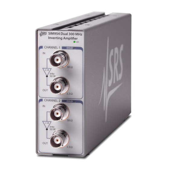
1 – 2 Operation 1.1 Description The SIM914 is a two-channel, 350 MHz bandwidth, DC-coupled, 50 Ω amplifier with a gain of 5 (+14 dB). The two channels may be cascaded for a gain of 25 (+28dB). The unit uses BNC connectors for inputs and outputs (see Figure 1.1). -
Page 7: Sim Interface Connector
Table 1.1: SIM Interface Connector pin assignments, DB-15. All other pins are left unconnected on the SIM914. 1.3.1 Grounding In the SIM914, all three ground lines (Pins 1, 8 & 9) are tied common to the chassis, and also form the signal ground. SIM914 350 MHz Preamplifier... -
Page 8: Direct Interfacing
SIM900 Mainframe via this connection, either through one of the internal Mainframe slots, or the remote cable interface. It is also possible to operate the SIM914 directly, without using the SIM900 Mainframe. This section provides details on the interface. -
Page 9: Specifications
2. Amplifier gain is calibrated by applying a known current to the input and measuring the voltage into a high impedance load. The gain is adjusted so that a 1 mA source applied to the input produces a 500 mV voltage at the unloaded output. SIM914 350 MHz Preamplifier... - Page 10 1 – 6 Operation SIM914 350 MHz Preamplifier...
-
Page 11: Calibration
2 Calibration This chapter describes how to adjust the SIM914 for optimum per- formance. The module should be warmed up for at least 15 minutes before making any adjustments. In This Chapter 2.1 General ......2 – 2 2.2 Required Equipment . -
Page 12: General
3. Oscilloscope with at least 300 MHz bandwidth. 2.3 High Frequency Compensation The SIM914 uses an AD8009 current feedback amplifier in the out- put stage. The gain of the amplifier is controlled by the ratio of re- sistors in the feedback network and the bandwidth is controlled by the Thevenin equivalent source impedance of the feedback network. -
Page 13: Offset Calibration
Take one cable from the tee to channel 1 of the oscilloscope (set to 50 Ω input termination) and the other to the top channel of the SIM914 via a 20 dB coaxial attenuator. 2. Adjust P102 (Channel 1 “HF COMP” pot) to match the output rise time and overshoot to the input rise time and overshoot. - Page 14 5. Verify that the offset was nulled by connecting the current source from the DMM to the input of the other channel and measuring a resistance of less than 1 Ω. 6. Repeat the gain adjustment for Channel 2 by adjusting P200. SIM914 350 MHz Preamplifier...
-
Page 15: Circuit Description
3 Circuit Description This chapter gives a general discussion of the circuitry in the SIM914. The two amplifier channels are identical. This description uses ref- erence designators in the top channel, Channel 1. In This Chapter 3.1 Input Stage ..... . . 3 – 2 3.2 Output Stage . -
Page 16: Input Stage
Overloads are detected at the output of the second gain stage, U101. A positive overload is rectified by D102 and charges C107. A nega- tive overload is rectified by D102 and discharges C106. One of the SIM914 350 MHz Preamplifier... -
Page 17: Power
300 MHz. The crosstalk from the output of Channel 2 to the input of Channel 1 is less than 80dB (1:10,000 of the amplitude) and occurs in a broad band between 180 MHz and 360 MHz. SIM914 350 MHz Preamplifier... -
Page 18: Parts List
Rear panel mounting 0-00515 4-40X1/8PP 3-01429 MMBZ5228B Module Cover Mounting 0-00371 4-40X3/16P D100,D101,D102,D200,D201, 3-00896 BAV99L Front Panel, SIM914 7-00987 D202 Lexan FP Overlay, SIM914 7-01353 D300 3-00424 LED-G Rear Panel, SIM914 7-01410 D301,D302 3-00425 LED-R SIM 1X BRACKET 7-00933 D303... -
Page 19: Schematic Diagrams
3.6 Schematic Diagrams 3 – 5 3.6 Schematic Diagrams Schematic diagrams follow this page. SIM914 350 MHz Preamplifier...
Need help?
Do you have a question about the SIM914 and is the answer not in the manual?
Questions and answers