Table of Contents
Advertisement
Quick Links
Operation and Service Manual
Distribution in the UK & Ireland
Characterisation,
Measurement &
Analysis
Stanford Research Systems
Lambda Photometrics Limited
Lambda House Batford Mill
Harpenden Herts AL5 5BZ
United Kingdom
E:
info@lambdaphoto.co.uk
W: www.lambdaphoto.co.uk
T:
+44 (0)1582 764334
F:
+44 (0)1582 712084
Isolation Amplifier
Revision 1.13 • March 11, 2013
SIM984
Advertisement
Chapters
Table of Contents

Related Manuals for Stanford Research Systems SIM984


Summary of Contents for Stanford Research Systems SIM984
- Page 1 Operation and Service Manual Isolation Amplifier SIM984 Stanford Research Systems Distribution in the UK & Ireland Lambda Photometrics Limited Lambda House Batford Mill Revision 1.13 • March 11, 2013 Harpenden Herts AL5 5BZ United Kingdom Characterisation, info@lambdaphoto.co.uk Measurement & W: www.lambdaphoto.co.uk...
- Page 2 (1) year from the date of shipment. Service For warranty service or repair, this product must be returned to a Stanford Research Systems authorized service facility. Contact Stanford Research Systems or an authorized representative before returning this product for repair.
-
Page 3: Table Of Contents
Contents General Information Symbols ......Notation ......Specifications . - Page 4 Contents SIM984 Isolation Amplifier...
-
Page 5: General Information
Do not install substitute parts or perform any unauthorized modifi- cations to this instrument. The SIM984 is a single-wide module designed to be used inside the SIM900 Mainframe. Do not turn on the power until the module is completely inserted into the mainframe and locked in place. -
Page 6: Symbols
General Information Symbols you may Find on SRS Products Symbol Description Alternating current Caution - risk of electric shock Frame or chassis terminal Caution - refer to accompanying documents Earth (ground) terminal Battery Fuse On (supply) Off (supply) SIM984 Isolation Amplifier... -
Page 7: Notation
• Literal text other than command names is set as OFF. Remote command examples will all be set in monospaced font. In these examples, data sent by the host computer to the SIM984 are set as straight teletype font, while responses received by the host computer from the SIM984 are set as slanted teletype font. -
Page 8: Specifications
+24 V (100 mA) General Characteristics Interface Serial (RS-232) through SIM interface Connectors banana jack (2 front) BNC (1 front, 1 rear) DB–15 (male) SIM interface Weight 1.5 lbs 1.5 W × 3.6 H × 7.0 D Dimensions SIM984 Isolation Amplifier... -
Page 9: Getting Started
1 Getting Started This chapter gives you the necessary information to get started quickly with the SIM984 Isolation Amplifier. In This Chapter Introduction to the Instrument ... . . 1 – 2 1.1.1... -
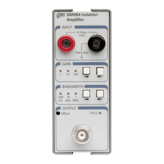
Page 10: Introduction To The Instrument
The front panel of the SIM984 (see Figure 1.1) provides a simple operator interface. 1.2.1 Inputs The input to the SIM984 is through the red and black banana jacks in the front-panel “INPUT” block. The banana jacks are isolated from the chassis for use with insulated test leads. -
Page 11: Bandwidth
If the output signal exceeds ±10 V, the output overload detection is activated. This is indicated by the red OVLD near the top of the “OUTPUT” block on the front panel. The SIM984 output offset voltage may be trimmed by adjusting the SIM984 Isolation Amplifier... -
Page 12: Sim Interface
SIM900 Mainframe via this connection, either through one of the internal Mainframe slots, or the remote cable interface. It is also possible to operate the SIM984 directly, without using the SIM900 Mainframe. This section provides details on the interface. -
Page 13: Direct Interfacing
RS-232 serial port of a personal computer. Connect RXD from the SIM984 directly to RD on the PC, TXD directly to TD. In other words, a null-modem style cable is not needed. To interface directly to the DB–9 male (DTE) RS-232 port typically found on personal computers, a cable must be made with a female DB–15 socket to mate with the SIM984, and a female DB–9 socket... - Page 14 7 ←→ −15 VDC 13 ←→ +5 VDC 14 ←→ +15 VDC 15 ←→ +24 VDC 8,9 ←→ Ground (P/S return current) 1 ←→ Signal Ground (separate wire to Ground) Table 1.2: SIM984 Direct Interface Cable Pin Assignments SIM984 Isolation Amplifier...
-
Page 15: Remote Operation
2 Remote Operation This chapter describes operating the SIM984 over the serial interface. In This Chapter Index of Common Commands ... . . 2 – 2 Alphabetic List of Commands ... . . 2 – 3 Introduction . -
Page 16: Index Of Common Commands
2 – 10 Console Mode LEXE? 2 – 10 Execution Error LCME? 2 – 11 Command Error PARI(?) {z} 2 – 11 Parity TOKN(?) {z} 2 – 11 Token Mode TERM(?) {z} 2 – 12 Response Termination SIM984 Isolation Amplifier... -
Page 17: Alphabetic List Of Commands
2 – 10 Execution Error OVLD? 2 – 8 Overload Condition PARI(?) {z} 2 – 11 Parity PSTA(?) {z} 2 – 9 Pulse −STATUS Mode TERM(?) {z} 2 – 12 Response Termination TOKN(?) {z} 2 – 11 Token Mode SIM984 Isolation Amplifier... -
Page 18: Introduction
2 – 4 Remote Operation 2.3 Introduction Remote operation of the SIM984 is through a simple command lan- guage documented in this chapter. Both set and query forms of most commands are supported, allowing the user complete control of the isolation amplifier from a remote computer, either through the SIM900 Mainframe or directly via RS-232 (see Section 1.3.2.1). -
Page 19: Command Syntax
CR + LF , the following two commands are equivalent: TERM CRLF TERM 3 —or— For queries that return token values, the return format (keyword or integer) is specified with the TOKN command. SIM984 Isolation Amplifier... -
Page 20: Notation
In these examples, all data sent by the host computer to the SIM984 are set as straight teletype font, while responses received the host computer from the SIM984 are set as slanted teletype font. The usage examples vary with respect to set/query, optional param- eters, and token formats. -
Page 21: Amplifier Commands
Example: BWTH? 2.4.5 Status Commands The Status commands query and configure registers associated with status reporting of the SIM984. *STB? [i] Status Byte Reads the Status Byte register [bit i]. Execution of the *STB? query (without the optional bit i) always causes the −STATUS signal to be deasserted. - Page 22 CESE(?) [i,]{j} Comm Error Status Enable Set (query) Comm Error Status Enable Register [for bit i] {to j} Example: CESE? OVLD? Overload Condition Query Overload Condition. If the SIM984 is overloading, OVLD? returns 1; otherwise 0. Example: OVLD? SIM984 Isolation Amplifier...
-
Page 23: Interface Commands
Example: PSTA? 2.4.6 Interface Commands Interface commands provide generic control over the interface be- tween the SIM984 and the host computer. *RST Reset Reset the SIM984 to default configuration. After *RST, the gain is set to ×1 and the bandwidth to DC–100 Hz. - Page 24 No execution error since last LEXE? Illegal value Wrong token Invalid bit Command not ready Example: *STB? 12; LEXE?; LEXE? The error (3, “Invalid bit,”) is because *STB? only allows bit-specific queries of 0–7. The second read of LEXE? returns 0. SIM984 Isolation Amplifier...
- Page 25 If TOKN ON is set, then queries to the SIM module that return to- kens will return the text keyword; otherwise they return the decimal integer value. Thus, the only possible responses to the TOKN? query are ON and 0. On reset, TOKN is set to OFF. Example: TOKN OFF SIM984 Isolation Amplifier...
- Page 26 LFCR 4)}. The term sequence is appended to all query responses sent by the module, and is constructed of ASCII character(s) 13 (car- riage return) and 10 (line feed). The token mnemonic gives the sequence of characters. At power-on, TERM is set to CRLF. Example: TERM? SIM984 Isolation Amplifier...
-
Page 27: Status Model
Enable register names end with SE. 2.5.1 Status Byte (SB) The Status Byte is the top-level summary of the SIM984 status model. When masked by the Service Request Enable register, a bit set in the Status Byte causes the −STATUS signal to be asserted on the rear- panel SIM interface connector. -
Page 28: Service Request Enable (Sre)
OVLD : Overload Bit. Indicates whether an amplifier overload has occurred. IDLE : Indicates that the Input Buffer is empty and the command parser is idle. Can be used to help synchronize SIM984 query responses. ESB : Event Status Bit. Indicates whether one or more of the enabled events in the Standard Event Status Register is true. -
Page 29: Standard Event Status (Esr)
Input Buffer. QYE : Query Error. Indicates data in the Output Queue has been lost. DDE : Device Dependent Error. This bit is undefined in the SIM984. EXE : Execution Error. Indicates an error in a command that was successfully parsed. Out-of-range parameters are an example. -
Page 30: Communication Error Status Enable (Cese)
RTSH : Undefined for the SIM984. CTSH : Undefined for the SIM984. DCAS : Device Clear. Indicates the SIM984 received the Device Clear signal (an RS-232 break ). Clears the Input Buffer and Output Queue, and resets the command parser. - Page 31 3 Circuits This chapter presents a brief description of the SIM984 circuit design. In This Chapter Circuit Descriptions ....3 – 2 3.1.1...
-
Page 32: Circuitry
3.1.4 Digital control The SIM984 is controlled by microcontroller U107. A critical aspect of the design is the clock-stop circuitry implemented by U102 and U105. A simple RC-oscillator is enabled or disabled at pin 1 of U102, which is driven by synchronizing flip-flop U105B to... -
Page 33: Schematic Diagrams
When the microcontroller has completed all pending activity, it drives the STOP signal high (pin 71 of U107), effectively halting its own processor clock. In this way, the SIM984 guarantees no digital clock artifacts can be generated during quiescent operation.
Need help?
Do you have a question about the SIM984 and is the answer not in the manual?
Questions and answers