
Related Manuals for Supermicro X11SSH-GF-1585


Summary of Contents for Supermicro X11SSH-GF-1585
- Page 1 X11SSH-GF-1585 X11SSH-GF-1585L X11SSH-GTF-1585 X11SSH-GTF-1585L USER’S MANUAL Revision 1.0a...
- Page 2 State of California, USA. The State of California, County of Santa Clara shall be the exclusive venue for the resolution of any such disputes. Supermicro's total liability for all claims will not exceed the price paid for the hardware product.
-
Page 3: About This Manual
Please note that this motherboard is intended to be installed and serviced by professional technicians only. For processor/memory updates, please refer to our website at http://www. supermicro.com/products/. Conventions Used in the Manual Special attention should be given to the following symbols for proper installation and to prevent... -
Page 4: Contacting Supermicro
Super Micro Computer, Inc. 980 Rock Ave. San Jose, CA 95131 U.S.A. Tel: +1 (408) 503-8000 Fax: +1 (408) 503-8008 Email: marketing@supermicro.com (General Information) support@supermicro.com (Technical Support) Website: www.supermicro.com Europe Address: Super Micro Computer B.V. Het Sterrenbeeld 28, 5215 ML... -
Page 5: Table Of Contents
Preface Table of Contents Chapter 1 Introduction 1.1 Checklist ..........................8 Quick Reference .......................11 Quick Reference Table ......................12 Motherboard Features .......................14 1.2 Processor and Chipset Overview ..................18 1.3 Special Features ........................18 Recovery from AC Power Loss ..................18 1.4 System Health Monitoring ....................19 Onboard Voltage Monitors ....................19 Fan Status Monitor with Firmware Control ...............19 Environmental Temperature Control .................19... - Page 6 X11SSH-GF/-GTF (-1585/-1585L) User's Manual SO-DIMM Removal ......................26 2.4 Rear I/O Ports ........................27 2.5 Front Control Panel ......................32 2.6 Connectors .........................36 Power Connections ......................36 Headers ..........................38 2.7 Jumper Settings .........................45 How Jumpers Work ......................45 2.8 LED Indicators ........................52 Chapter 3 Troubleshooting 3.1 Troubleshooting Procedures ....................54 Before Power On ......................54 No Power ..........................54...
- Page 7 4.6 Security ..........................92 4.7 Boot Settings ........................94 4.8 Save & Exit .........................96 Appendix A BIOS Codes Appendix B Software Installation B.1 Installing Software Programs ...................100 B.2 SuperDoctor 5 .........................101 ® Appendix C Standardized Warning Statements Battery Handling ......................102 Product Disposal ......................104 Appendix D UEFI BIOS Recovery...
-
Page 8: Chapter 1 Introduction
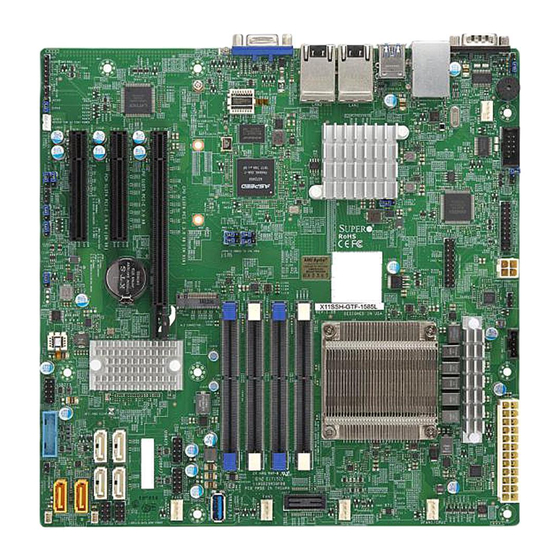
Introduction Congratulations on purchasing your computer motherboard from an industry leader. Supermicro motherboards are designed to provide you with the highest standards in quality and performance. In addition to the motherboard, the following items are included in your shipping package. If anything listed is damaged or missing, please contact your retailer. - Page 9 Chapter 1: Introduction Figure 1-1. X11SSH-GF/-GTF (-1585/1585L) Motherboard Image Note: All graphics shown in this manual were based upon the latest PCB revision available at the time of publishing of the manual. The motherboard you received may or may not look exactly the same as the graphics shown in this manual.
- Page 10 X11SSH-GF/-GTF (-1585/-1585L) User's Manual Figure 1-2. X11SSH-GF/-GTF (-1585/1585L) Motherboard Layout (not drawn to scale) COM1 USB8/9 (3.0) MH10 USB0/1 LAN2 LAN1 IPMI_LAN JSTBY1 LEDM1 JPL1 X11SSH-GF-1585L REV:1.01 JPB1 JPG1 DESIGNED IN USA JVRM2 JVRM1 LED2 BAR CODE BIOS LICENSE IPMI CODE JPME2 JPWR2 MAC CODE...
-
Page 11: Quick Reference
Chapter 1: Introduction COM1 USB8/9 COM1 (3.0) MH10 USB0/1 LEDM1 LAN2 LAN1 JPL1 USB8/9 IPMI_LAN (3.0) JSTBY1 MH10 X11SSH-GF-1585L USB0/1 REV:1.01 LAN2 LAN1 JPB1 JPG1 IPMI_LAN DESIGNED IN USA JVRM2 JVRM1 LED2 JSTBY1 Quick Reference BAR CODE BIOS LICENSE IPMI CODE JPME2 JPWR2 MAC CODE... -
Page 12: Quick Reference Table
X11SSH-GF/-GTF (-1585/-1585L) User's Manual Quick Reference Table Jumper Description Default Setting JBR1 BIOS Recovery Pins 1-2 (Normal) JBT1 CMOS Clear Open (Normal) C1/JI SMB to PCI-E Slots Enable/Disable Pins 2-3 (Disabled) JLED1 Power LED Enable/Disable Pins 1-2 (Enabled) JPB1 BMC Enable/Disable Pins 1-2 (Enabled) JPG1 VGA Enable/Disable... - Page 13 Chapter 1: Introduction Connector Description SLOT5 PCI-Express 3.0 X8 Slot supported by the CPU SLOT6 PCI-Express 3.0 X8 (IN X16) Slot supported by the CPU Internal Speaker/Buzzer USB0/1 Back Panel Universal Serial Bus (USB) 2.0 Port USB2/3, 4/5, 6/7 USB 2.0 Header USB8/9 Back Panel Universal Serial Bus (USB) 3.0 Port USB10/11...
-
Page 14: Motherboard Features
X11SSH-GF/-GTF (-1585/-1585L) User's Manual Motherboard Features Motherboard Features • Single Intel® Xeon® E3-1500 v5 processor in a BGA socket Memory • Integrated memory controller supports up to 64GB of unbuffered DDR4 ECC SO-DIMM 2400MHz memory DIMM Size • Up to a total of 64GB at 1.2V in four (4) DIMM slots Chipset •... - Page 15 System resource alert via SuperDoctor® 5 • Chassis intrusion detection • Watch Dog, NMI (Non-maskable interrupt), RoHS (Restriction of Hazardous Substance Directive) • SPM (Supermicro Power Management), SUM (Supermicro Update Manager) with In-Band and Out-of-Band channels LED Indicators • CPU/system overheat • Power suspend-state •...
- Page 16 User's Guide available at http://www.supermicro.com/support/manuals/. Note 3: It is strongly recommended that you change BMC log-in information upon initial system power-on. The manufacture default username is ADMIN and the password is ADMIN. For proper BMC configuration, please refer to http://www.supermicro.com/ products/info/files/IPMI/Best_Practices_BMC_Security.pdf...
-
Page 17: System Block Diagram
Chapter 1: Introduction Figure 1-3. System Block Diagram IMVP 8 2 PHASE for Vcore #B-1 1 PHASE for VSA #B-0 #A-1 #A-0 PCI-E X8 8.0 Gb/S Xeon PCIe 3.0 x8 ( in X16) #0-7 BGA1440 PCI-E X8 8.0 Gb/S PCIe 3.0 x8 #8-15 DMI3 DMI3 x4... -
Page 18: Processor And Chipset Overview
X11SSH-GF/-GTF (-1585/-1585L) User's Manual 1.2 Processor and Chipset Overview Built upon the functionality and capability of the Intel® E3-1500 v5 (E3-1585 v5/65W; E3-1585L v5/45W) series processors (Socket BGA 1440) and the Intel® C236 PCH, the X11SSH-GF/-GTF (-1585/-1585L) motherboard offers maximum I/O expandability, energy efficiency, and data reliability in a 14-nm process architecture, and is optimized for embedded storage solutions, networking applications, and cloud-computing platforms. -
Page 19: System Health Monitoring
Chapter 1: Introduction 1.4 System Health Monitoring This section describes the health monitoring features of the X11SSH-GF/-GTF (-1585/-1585L) motherboard. The motherboard has an onboard Baseboard Management Controller (BMC) chip that supports system health monitoring. Once a voltage becomes unstable, a warning is given or an error message is sent to the screen. -
Page 20: Acpi Features
X11SSH-GF/-GTF (-1585/-1585L) User's Manual 1.5 ACPI Features ACPI stands for Advanced Configuration and Power Interface. The ACPI specification defines a flexible and abstract hardware interface that provides a standard way to integrate power management features throughout a computer system including its hardware, operating system and application software. -
Page 21: Advanced Power Management
Intelligent Power Node Manager (IPNM) ® Available when the Supermicro Power Manager (SPM) is installed, Intel's Intelligent Power Node Manager (IPNM) provides your system with real-time thermal control and power management for maximum energy efficiency. Although IPNM Specification Version 2.0/3.0 is supported by the BMC (Baseboard Management Controller), your system must also have IPNM-compatible Management Engine (ME) firmware installed to use this feature. -
Page 22: Chapter 2 Installation
X11SSH-GF/-GTF (-1585/-1585L) User's Manual Chapter 2 Installation 2.1 Static-Sensitive Devices Electrostatic Discharge (ESD) can damage electronic com ponents. To prevent damage to your motherboard, it is important to handle it very carefully. The following measures are generally sufficient to protect your equipment from ESD. Precautions •... -
Page 23: Motherboard Installation
Chapter 2: Installation 2.2 Motherboard Installation All motherboards have standard mounting holes to fit different types of chassis. Make sure that the locations of all the mounting holes for both the motherboard and the chassis match. Although a chassis may have both plastic and metal mounting fasteners, metal ones are highly recommended because they ground the motherboard to the chassis. -
Page 24: Installing The Motherboard
X11SSH-GF/-GTF (-1585/-1585L) User's Manual Installing the Motherboard 1. Install the I/O shield into the back of the chassis. 2. Locate the mounting holes on the motherboard. See the previous page for the location. 3. Locate the matching mounting holes on the chassis. Align the mounting holes on the motherboard against the mounting holes on the chassis. -
Page 25: Memory Support And Installation
Chapter 2: Installation 2.3 Memory Support and Installation Note: Check the Supermicro website for recommended memory modules. Important: Exercise extreme care when installing or removing DIMM modules to pre- vent any possible damage. Memory Support The X11SSH-GF/-GTF (-1585/-1585L) supports up to 64GB of DDR4 ECC SO-DIMM 2400MHz memory. -
Page 26: So-Dimm Installation
X11SSH-GF/-GTF (-1585/-1585L) User's Manual SO-DIMM Installation COM1 USB8/9 1. Insert SO-DIMM modules in the following (3.0) MH10 USB0/1 LAN2 LAN1 IPMI_LAN JSTBY1 order: DIMMA1, DIMMB1, DIMMA2, and DIMMB2. For the system to work properly, LEDM1 JPL1 X11SSH-GF-1585L REV:1.01 please use memory modules of the same JPB1 JPG1 JVRM2... -
Page 27: Rear I/O Ports
Chapter 2: Installation 2.4 Rear I/O Ports See Figure 2-2 below for the locations and descriptions of the various I/O ports on the rear of the motherboard. COM1 USB8/9 (3.0) MH10 USB0/1 LAN2 LAN1 IPMI_LAN JSTBY1 LEDM1 JPL1 X11SSH-GF-1585L REV:1.01 JPB1 JPG1 DESIGNED IN USA... -
Page 28: Lan Ports
X11SSH-GF/-GTF (-1585/-1585L) User's Manual LAN Ports Two LAN ports (LAN1 ~ LAN2) are located on the I/O back panel. These ports accept RJ45 type cables. See the table below for pin definitions. LAN1/2 Ports Pin Definions Pin # Definition Pin # Definition TRD1+ TRCT1... - Page 29 Chapter 2: Installation IPMI LAN Port There is one IPMI LAN port on the I/O back panel dedicated to the BMC (Baseboard Management Controller). This port accepts RJ45 type cables. IPMI_LAN Pin Definion Pin # Definition Pin # Definition TX1- YEL+ TX1+ YEL-...
-
Page 30: Serial Ports
X11SSH-GF/-GTF (-1585/-1585L) User's Manual VGA Port A VGA port is located on the I/O back panel. This port is used to provide video display. Serial Ports Serial port COM1 is located next to USB 0/1 on the I/O back panel. Another Serial port header (COM2) is on the motherboard. -
Page 31: Usb Ports
Chapter 2: Installation USB Ports This motherboard supports four USB 3.0 connections: two on the motherboard (USB 8/9), an another two on the I/O back panel (USB 0/1). A Type A USB connector (USB 12), located next to Fan3, also provides USB 3.0 support for front access. In addition, three USB 2.0 headers are also located on the motherboard and provide six USB 2.0 connections for front access support (USB 2/3, 4/5, 6/7). -
Page 32: Front Control Panel
JF1 contains header pins for various buttons and indicators that are normally located on a control panel at the front of the chassis. These connectors are designed specifically for use with Supermicro chassis. See the figure below for the descriptions of the front control panel buttons and LED indicators. - Page 33 Chapter 2: Installation Power LED The Power LED connection is located on pins 15 and 16 of JF1. Refer to the table below for pin definitions. Power LED Pin Definitions (JF1) Pin# Definition +3.3V Stby Power LED HDD LED The HDD LED connection is located on pins 13 and 14 of JF1. Attach a cable here to indicate the status of HDD-related activities, including SATA activities.
- Page 34 X11SSH-GF/-GTF (-1585/-1585L) User's Manual Reset Button The Reset Button connection is located on pins 3 and 4 of JF1. Attach it to a hardware reset switch on the computer case to reset the system. Refer to the table below for pin definitions. Reset Button Pin Definitions (JF1) Pin#...
-
Page 35: Nmi Button
Chapter 2: Installation Power Supply Fail Connect an LED cable to Power Supply Fail connections on pins 5 and 6 of JF1 to provide warnings for a power failure. Refer to the table below for pin definitions. Power Supply Fail Indicator Status Pin# Definition... -
Page 36: Connectors
X11SSH-GF/-GTF (-1585/-1585L) User's Manual 2.6 Connectors Power Connections Main ATX Power Supply Connector The primary power supply connector (JPWR1) meets the ATX SSI EPS 24-pin specification. You must also connect the 4-pin (JPWR2) CPU power connector to your power supply. ATX Power 24-pin Connector Pin Definitions Pin#... - Page 37 Chapter 2: Installation 12V DC Power Connector JPWR2 must also be connected to the power supply. This connector is used to power the processor(s). +12V 4-pin Power Pin Definitions Pin# Definition Ground Required Connection 1. 4-Pin Secondary Power COM1 USB8/9 (3.0) MH10 USB0/1...
-
Page 38: Headers
X11SSH-GF/-GTF (-1585/-1585L) User's Manual Headers Fan Headers There are four 4-pin fan headers on the motherboard. Pins 1-3 of the fan header are backward-compatible with traditional 3-pin fans. Pin 4 of the fan is used for PWM (Pulse-Width Module) control support. The onboard fan speeds are controlled by Thermal Management (via Hardware Monitoring) in the BIOS. - Page 39 Chapter 2: Installation Disk-On-Module Power Connector The Disk-On-Module (DOM) power connectors at JSD1 and JSD2 provide 5V power to a solid-state DOM storage device connected to one of the SATA ports. See the table below for pin definitions. DOM Power Pin Definitions Pin# Definition...
- Page 40 It enables the motherboard to deny access if the TPM associated with the hard drive is not installed in the system. Please go to the following link for more information on TPM: http://www.supermicro.com/manuals/other/TPM.pdf. See the table below for pin definitions. Trusted Platform Module Header...
-
Page 41: Chassis Intrusion
Chapter 2: Installation Chassis Intrusion A Chassis Intrusion header is located at JL1 on the motherboard. Attach the appropriate cable from the chassis to the header to inform you when the chassis is opened. Chassis Intrusion Pin Definitions Pins Definition Intrusion Input Ground M.2 Slot... - Page 42 Note: UID can also be triggered via IPMI on the motherboard. For more informa- tion on IPMI, please refer to the IPMI User's Guide posted on our website at http:// www.supermicro.com. UID Switch UID LED...
-
Page 43: Standby Power
Chapter 2: Installation Power SMB (I C) Header The Power System Management Bus (I C) connector at JPI C1 monitors the power supply, fan, and system temperatures. See the table below for pin definitions. Power SMB Header Pin Definitions Pin# Definition Clock Data... - Page 44 X11SSH-GF/-GTF (-1585/-1585L) User's Manual Internal Speaker/Buzzer The Internal Speaker/Buzzer (SP1) is used to provide audible indications for various beep codes. See the table on the right for pin definitions. Internal Buzzer Pin Definition Pin# Definitions Pos. (+) Beep In Neg. (-) Alarm Speaker 1.
-
Page 45: Jumper Settings
Chapter 2: Installation 2.7 Jumper Settings How Jumpers Work To modify the operation of the motherboard, jumpers can be used to choose between optional settings. Jumpers create shorts between two pins to change the function of the connector. Pin 1 is identified with a square solder pad on the printed circuit board. See the diagram at right for an example of jumping pins 1 and 2. - Page 46 X11SSH-GF/-GTF (-1585/-1585L) User's Manual SMBus to PCI Slots Jumpers JI C1 and JI C2 allow you to connect the System Management Bus (I C) to the PCI-E/PCI slots. Both jumpers must be set to the same setting (JI C1 controls the clock and C2 controls the data).
-
Page 47: Me Manufacturing Mode
Chapter 2: Installation ME Manufacturing Mode JPME2 allows you to bypass SPI flash security and force the system to use the Manufacturing Mode, which will allow you to flash the system firmware from a host server to modify system settings. Refer to the table below for jumper settings. ME Recovery Jumper Settings Jumper Setting... - Page 48 X11SSH-GF/-GTF (-1585/-1585L) User's Manual Watch Dog JWD1 controls the Watch Dog function. Watch Dog is a monitor that can reboot the system when a software application hangs. Jumping pins 1-2 will cause Watch Dog to reset the system if an application hangs. Jumping pins 2-3 will generate a non-maskable interrupt signal for the application that hangs.
-
Page 49: Bios Recovery
Chapter 2: Installation BIOS Recovery Use jumper JBR1 to recover the BIOS settings. The default setting is Normal. See the table below for jumper settings. BIOS Recovery Jumper Settings Jumper Setting Definition Pins 1-2 Normal Pins 2-3 BIOS Recovery 1. BIOS Recovery COM1 USB8/9 (3.0) -
Page 50: Vga Connector
X11SSH-GF/-GTF (-1585/-1585L) User's Manual VGA Connector Jumper JPG1 allows the user to enable the onboard VGA connector. The default settting is pins 1-2 to enable the connection. See the table below for jumper settings. VGA Enable Jumper Settings Jumper Setting Definition Pins 1-2 Enabled (Default) - Page 51 Chapter 2: Installation Power LED Enable/Disable An onboard Power LED header is located at JLED1. This Power LED header is connected to the front control panel located at JF1 to indicate the status of system power. See the table below for pin definitions. Onboard PWR LED Jumper Settings Jumper Setting...
-
Page 52: Led Indicators
X11SSH-GF/-GTF (-1585/-1585L) User's Manual 2.8 LED Indicators Unit ID LED A rear UID LED indicator at LED1 is located next to the I/O back panel. The UID indicator provides easy identifiication of a system unit that may be in need of service. Refer to the table for the LED status. - Page 53 Chapter 2: Installation BMC Heartbeat LED LEDM1 is the BMC heartbeat LED. When the LED is blinking green, BMC is functioning normally. See the table below for the LED status. BMC Heartbeat LED Indicator LED Color Definition Green: BMC Normal Blinking Dedicated IPMI LAN LED A dedicated IPMI LAN is also included on the motherboard.
-
Page 54: Chapter 3 Troubleshooting
X11SSH-GF/-GTF (-1585/-1585L) User's Manual Chapter 3 Troubleshooting 3.1 Troubleshooting Procedures Use the following procedures to troubleshoot your system. If you have followed all of the procedures below and still need assistance, refer to the ‘Technical Support Procedures’ and/ or ‘Returning Merchandise for Service’ section(s) in this chapter. Always disconnect the AC power cord before adding, changing or installing any non hot-swap hardware components. -
Page 55: No Video
Chapter 3: Troubleshooting No Video 1. If the power is on, but you have no video, remove all the add-on cards and cables. 2. Use the speaker to determine if any beep codes exist. Refer to Appendix A for details on beep codes. -
Page 56: Losing The System's Setup Configuration
2. Memory support: Make sure that the memory modules are supported by testing the modules using memtest86 or a similar utility. Note: Refer to the product page on our website at http:\\www.supermicro.com memory and CPU support and updates. 3. HDD support: Make sure that all hard disk drives (HDDs) work properly. Replace the bad HDDs with good ones. - Page 57 Chapter 3: Troubleshooting 3. Using the minimum configuration for troubleshooting: Remove all unnecessary components (starting with add-on cards first), and use the minimum configuration (but with a CPU and a memory module installed) to identify the trouble areas. Refer to the steps listed in Section A above for proper troubleshooting procedures.
-
Page 58: Technical Support Procedures
X11SSH-GF/-GTF (-1585/-1585L) User's Manual 3.2 Technical Support Procedures Before contacting Technical Support, please take the following steps. Also, note that as a motherboard manufacturer, we do not sell directly to end-users, so it is best to first check with your distributor or reseller for troubleshooting services. They should know of any possible problem(s) with the specific system configuration that was sold to you. -
Page 59: Frequently Asked Questions
Updated BIOS files are located on our website at http://www. supermicro.com. Please check our BIOS warning message and the information on how to update your BIOS on our website. Select your motherboard model and download the BIOS file to your computer. -
Page 60: Battery Removal And Installation
X11SSH-GF/-GTF (-1585/-1585L) User's Manual 3.4 Battery Removal and Installation Battery Removal To remove the onboard battery, follow the steps below: 1. Power off your system and unplug your power cable. 2. Locate the onboard battery as shown below. 3. Using a tool such as a pen or a small screwdriver, push the battery lock outwards to unlock it. -
Page 61: Returning Merchandise For Service
Shipping and handling charges will be applied for all orders that must be mailed when service is complete. For faster service, RMA authorizations may be requested online (http://www.supermicro.com/ support/rma/). This warranty only covers normal consumer use and does not cover damages incurred in shipping or from failure due to the alteration, misuse, abuse or improper maintenance of products. -
Page 62: Chapter 4 Bios
X11SSH-GF/-GTF (-1585/-1585L) User's Manual Chapter 4 BIOS 4.1 Introduction This chapter describes the AMIBIOS™ setup utility for the X11SSH-GF/-GTF (-1585/-1585L) motherboard. The BIOS is stored on a Flash EEPROM and can be easily upgraded using a flash program. Note: Due to periodic changes to the BIOS, some settings may have been added or deleted and might not yet be recorded in this manual. -
Page 63: How To Change The Configuration Data
Note: For AMI UEFI BIOS Recovery, please refer to the UEFI BIOS Recovery User Guide posted at http://www.supermicro.com/support/manuals/. 4.2 Main Setup When you first enter the AMI BIOS setup utility, you will enter the Main setup screen. You can always return to the Main setup screen by selecting the Main tab on the top of the screen. - Page 64 HH:MM:SS format. Note: The time is in the 24-hour format. For example, 5:30 P.M. appears as 17:30:00. The date's default value is 01/01/2014 after RTC reset. Supermicro X11SSH-GTF-1585L BIOS Version This item displays the version of the BIOS ROM used in the system.
-
Page 65: Advanced Setup Configurations
Chapter 4: BIOS 4.3 Advanced Setup Configurations Use the arrow keys to select Boot Setup and press <Enter> to access the submenu items. Warning: Take caution when changing the Advanced settings. An incorrect value, an inaccurate DRAM frequency, or a wrong DRAM timing setting may make the system unstable. When this occurs, revert the setting to the manufacture default settings. -
Page 66: Power Configuration
X11SSH-GF/-GTF (-1585/-1585L) User's Manual immediately and allow the drives that are attached to these host adaptors to function as bootable disks. If this item is set to Postponed, the ROM BIOS of the host adaptors will not capture Interrupt 19 immediately and allow the drives attached to these adaptors to function as bootable devices at bootup. - Page 67 Chapter 4: BIOS • Max CPU Speed • Min CPU Speed • CPU Speed • Processor Cores • Hyper Threading Technology • Intel VT-x Technology • Intel SMX Technology • 64-bit • EIST Technology • CPU C3 State • CPU C6 State •...
- Page 68 X11SSH-GF/-GTF (-1585/-1585L) User's Manual Active Processor Cores This feature determines how many CPU cores will be activated for each CPU. When all is selected, all cores in the CPU will be activated. (Please refer to Intel's website for more information.) The options are All 1,2, and 3. Execute Disable Bit (Available if supported by the OS &...
- Page 69 Chapter 4: BIOS HardWare P-States (HWP) Use this feature to enable or disable hardware P-States support. The options are Disabled and Enabled. Intel ® SpeedStep™ Intel® SpeedStep Technology allows the system to automatically adjust processor voltage and core frequency to reduce power consumption and heat dissipation. The options are Disabled and Enabled.
- Page 70 X11SSH-GF/-GTF (-1585/-1585L) User's Manual 4-Core Ratio Limit Override This increases (multiplies) 4 clock speeds in the CPU core in relation to the bus speed when three CPU cores are active. Press "+" or "-" on your keyboard to change the value. Enter 0 to use the manufacture default setting.
-
Page 71: Chipset Configuration
Chapter 4: BIOS ACPI 3.0 T-States Select Enabled to support CPU throttling by the operating system to reduce power consumption. The options are Disabled and Enabled . Chipset Configuration Warning: Setting the wrong values in the following features may cause the system to malfunc- tion. - Page 72 X11SSH-GF/-GTF (-1585/-1585L) User's Manual Internal Graphics Select Auto to keep an internal graphics device installed on an expansion slot supported by the CPU to be automatically enabled. The options are Auto, Disabled, and Enabled. GTT Size Use this feature to set the memory size to be used by the graphics translation table (GTT). The options are 2MB, 4MB, and 8MB.
- Page 73 Chapter 4: BIOS DMI VC1 Control Use this feature to enable or disable DMI Virtual Channel 1. The options are Enabled and Disabled. DMI VCm Control Use this feature to enable or disable the DMI Virtual Channel map. The options are Enabled and Disabled.
- Page 74 X11SSH-GF/-GTF (-1585/-1585L) User's Manual SLOT5 Power Limit Value Use this feature to set the upper limit on the power supplied by the PCIE slot. Press "+" or "-" on your keyboard to change this value. The default setting is 75. SLOT5 Power Limit Scale Use this feature to select the scale used for the slot power limit value.
-
Page 75: Memory Configuration
Chapter 4: BIOS Memory Configuration The following memory information will be displayed: • Memory RC Version • Memory Frequency • Total Memory • • DIMMA1 • DIMMA2 • DIMMB1 • DIMMB2 • Memory Timings (tCL-tRCD-tRP-tRAS) Maximum Memory Frequency Use this feature to set the maximum memory frequency for onboard memory modules. The options are Auto, 1067, 1200, 1333, 1400, 1600, 1800, 1867, 2000, 2133, 2200, 2400, 2600, 2667, 2800, 2933, 3000, and 3200. -
Page 76: Pci Express Configuration
X11SSH-GF/-GTF (-1585/-1585L) User's Manual REFRESH_2X_MODE Use this feature to select the refresh mode. The options are Disabled, 1-Enabled for WARM or HOT, and 2-Enabled HOT only. Closed Loop Thermal Throttling Management Select Enabled to support Closed-Loop Thermal Throttling which will improve reliability and reduces CPU power consumption via automatic voltage control while the CPU are in idle states. - Page 77 Chapter 4: BIOS ASPM level based on the system configuration. Select Disabled to disable ASPM support. The options are Disabled, L0s, L1, L0s & L1, and Auto. SLOT4 L1 Substates Use this feature to configure the PCI Express L1 substates. The options are Disabled, L1.1, L1.2, and L1.1 &...
-
Page 78: Sata Configuration
X11SSH-GF/-GTF (-1585/-1585L) User's Manual PCIe PLL SSC Select Enabled to enable Phase Locked Loop (PLL) support on the Spread Spectrum Clock (SSC) settings to help reduce Electromagnetic Interference caused by the components in the system. Select Disabled to enhance system stability. The options are Disabled and Enabled SATA Configuration ... - Page 79 Chapter 4: BIOS Port 0 ~ Port 7 Spin Up Device On an edge detect from 0 to 1, set this item to allow the PCH to initialize the device. The options are Enabled and Disabled. Port 0 ~ Port 7 SATA Device Type Use this item to specify if the SATA port specified by the user should be connected to a Solid State drive or a Hard Disk Drive.
-
Page 80: Usb Configuration
X11SSH-GF/-GTF (-1585/-1585L) User's Manual Onboard LAN1 Option ROM Use this option to select the type of device installed in LAN Port1 used for system boot. The default setting for this item is Enabled. Onboard LAN2 Option ROM Use this option to select the type of device installed in a LAN port specified by user for system boot. -
Page 81: Super Io Configuration
Chapter 4: BIOS XHCI Hand-Off This item is for operating systems that do not support eXtensible Host Controller Interface (XHCI) hand-off. When this item is enabled, XHCI ownership change will be claimed by the XHCI driver. The settings are Enabled and Disabled. Port 60/64 Emulation Select Enabled for I/O port 60h/64h emulation support which will provide complete USB keyboard legacy support for the operating system that does not support Legacy USB devices. -
Page 82: Intel Server Platform Services
X11SSH-GF/-GTF (-1585/-1585L) User's Manual Serial Port 2 Change Settings This feature specifies the base I/O port address and the Interrupt Request address of a serial port specified by the user. Select Auto to allow the BIOS to automatically assign the base I/O and IRQ address. -
Page 83: Serial Port Console Redirection
Chapter 4: BIOS Serial Port Console Redirection COM1 COM1 Console Redirection Select Enabled to enable console redirection support for a serial port specified by the user. The options are Disabled and Enabled. If this feature is set to Enabled, the following items will become available: COM1 Console Redirection Settings This feature allows the user to specify how the host computer will exchange data with the... - Page 84 X11SSH-GF/-GTF (-1585/-1585L) User's Manual COM1 Flow Control Use this feature to set the flow control for Console Redirection to prevent data loss caused by the overflow of the buffer. Send a "Stop" signal to stop sending data when the receiving buffer is full.
- Page 85 Chapter 4: BIOS SOL/COM2 Console Redirection Settings Use this feature to specify how the host computer will exchange data with the client computer, which is the remote computer used by the user. COM2 Terminal Type Use this feature to select the target terminal emulation type for Console Redirection. Select VT100 to use the ASCII Character set.
- Page 86 X11SSH-GF/-GTF (-1585/-1585L) User's Manual COM2 Recorder Mode Select Enabled to capture the data displayed on a terminal and send it as text messages to a remote server. The options are Disabled and Enabled. COM2 Resolution 100x31 Select Enabled for extended-terminal resolution support. The options are Disabled and Enabled.
-
Page 87: Acpi Settings
Chapter 4: BIOS Terminal Type Use this feature to select the target terminal emulation type for Console Redirection. Select VT100 to use the ASCII character set. Select VT100+ to add color and function key support. Select ANSI to use the extended ASCII character set. Select VT-UTF8 to use UTF8 encoding to map Unicode characters into one or more bytes. -
Page 88: Iscsi Configuration
X11SSH-GF/-GTF (-1585/-1585L) User's Manual The High Performance Event Timer is used to replace the 8254 Programmable Interval Timer. The options are Disabled and Enabled. WHEA Support This feature Enables the Windows Hardware Error Architecture (WHEA) support for the Windows 2008 (or a later version) operating system. The options are Disabled and Enabled. iSCSi Configuration ... -
Page 89: View Smbios Event Log
Chapter 4: BIOS Enabling/Disabling Options SMBIOS Event Log Select Enabled to enable SMBIOS (System Management BIOS) Event Logging during system boot. The options are Disabled and Enabled. Erasing Settings Erase Event Log Select Yes to erase all error events in the SMBIOS (System Management BIOS) log before an event logging is initialized at bootup. -
Page 90: Ipmi
X11SSH-GF/-GTF (-1585/-1585L) User's Manual 4.5 IPMI This submenu allows the user to configure Intelligent Platform Management Interface (IPMI) settings. The following IPMI information will be displayed: • BMC Firmware Revision • IPMI STATUS System Event Log Enabling/Disabling Options SEL Components Select Enabled to enable all system event logging support at bootup. -
Page 91: Bmc Network Configuration
Chapter 4: BIOS BMC Network Configuration The following items will be displayed: • IPMI LAN Selection • IPMI Network Link Status Update IPMI LAN Configuration Select Yes for the system BIOS to automatically reset the following IPMI settings upon next system boot. -
Page 92: Security
X11SSH-GF/-GTF (-1585/-1585L) User's Manual 4.6 Security This menu allows the user to configure the following security settings for the system. Password Check Select Setup for the system to check for a password at Setup. Select Always for the system to check for a password at bootup or upon entering the BIOS Setup utility. The options are Setup and Always. -
Page 93: Key Management
Chapter 4: BIOS Key Management This submenu allows the user to configure the following Key Management settings. *If the item above -"Secure Boot Mode" is set to Custom, the following items will be displayed: Provision Factory Default Keys (Available when the system is in Setup Mode) Select Enabled to install factory default secure-boot keys. -
Page 94: Boot Settings
X11SSH-GF/-GTF (-1585/-1585L) User's Manual 4.7 Boot Settings This submenu allows the user to configure Boot settings for this system: Boot Configuration Boot Mode Select Use this item to select the type of device to be used for system boot. The options are Legacy, UEFI, and Dual. - Page 95 Chapter 4: BIOS Delete Boot Option Use this item to select a boot device to delete from the boot priority list. Delete Boot Option Select the target boot device to delete from the boot priority list. *If devices are detected by the system, the following items will be displayed. The default options list devices that have been connected to your system.
-
Page 96: Save & Exit
X11SSH-GF/-GTF (-1585/-1585L) User's Manual 4.8 Save & Exit Select the Exit tab from the BIOS setup utility screen to enter the Exit BIOS Setup screen. Save Options Discard Changes and Exit Select this option to quit the BIOS Setup without making any permanent changes to the system configuration, and reboot the computer. - Page 97 Chapter 4: BIOS Save as User Defaults To set this feature, select Save as User Defaults from the Exit menu and press <Enter>. This enables the user to save any changes to the BIOS setup for future use. Restore User Defaults To set this feature, select Restore User Defaults from the Exit menu and press <Enter>.
-
Page 98: Appendix A Bios Codes
X11SSH-GF/-GTF (-1585/-1585L) User's Manual Appendix A BIOS Codes A.1 BIOS Error POST (Beep) Codes During the POST (Power-On Self-Test) routines, which are performed each time the system is powered on, errors may occur. Non-fatal errors are those which, in most cases, allow the system to continue with the boot- up process. - Page 99 When BIOS performs the Power On Self Test, it writes checkpoint codes to I/O port 0080h. If the computer cannot complete the boot process, a diagnostic card can be attached to the computer to read I/O port 0080h (Supermicro p/n AOC-LPC80-20). For information on AMI updates, please refer to http://www.ami.com/products/.
-
Page 100: Appendix B Software Installation
Appendix B Software Installation B.1 Installing Software Programs The Supermicro FTP site contains drivers and utilities for your system at ftp://ftp.supermicro. com. Some of these must be installed, such as the chipset driver. After accessing the FTP site, go into the CDR_Images directory and locate the ISO file for your motherboard. -
Page 101: Superdoctor ® 5
SATA settings back to your original settings. B.2 SuperDoctor ® The Supermicro SuperDoctor 5 is a hardware monitoring program that functions in a command-line or web-based interface in Windows and Linux operating systems. The program monitors system health information such as CPU temperature, system voltages, system power consumption, fan speed, and provides alerts via email or Simple Network Management Protocol (SNMP). -
Page 102: Appendix C Standardized Warning Statements
The following statements are industry standard warnings, provided to warn the user of situations which have the potential for bodily injury. Should you have questions or experience difficulty, contact Supermicro's Technical Support department for assistance. Only certified technicians should attempt to install or configure components. - Page 103 Appendix C: Warning Statements Attention Danger d'explosion si la pile n'est pas remplacée correctement. Ne la remplacer que par une pile de type semblable ou équivalent, recommandée par le fabricant. Jeter les piles usagées conformément aux instructions du fabricant. ¡Advertencia! Existe peligro de explosión si la batería se reemplaza de manera incorrecta.
-
Page 104: Product Disposal
X11SSH-GF/-GTF (-1585/-1585L) User's Manual Product Disposal Warning! Ultimate disposal of this product should be handled according to all national laws and regulations. 製品の廃棄 この製品を廃棄処分する場合、 国の関係する全ての法律 ・ 条例に従い処理する必要があります。 警告 本产品的废弃处理应根据所有国家的法律和规章进行。 警告 本產品的廢棄處理應根據所有國家的法律和規章進行。 Warnung Die Entsorgung dieses Produkts sollte gemäß allen Bestimmungen und Gesetzen des Landes erfolgen. -
Page 105: Appendix D Uefi Bios Recovery
Warning: Do not upgrade the BIOS unless your system has a BIOS-related issue. Flashing the wrong BIOS can cause irreparable damage to the system. In no event shall Supermicro be liable for direct, indirect, special, incidental, or consequential damages arising from a BIOS update. - Page 106 USB device or a writable CD/DVD. Note 1: If you cannot locate the "Super.ROM" file in your drive disk, visit our website www.supermicro.com to download the BIOS package. Extract the BIOS binary image into a USB flash device and rename it "Super.ROM" for BIOS recovery use.
- Page 107 Appendix D: UEFI BIOS Recovery 3. After locating the healthy BIOS binary image, the system will enter the BIOS Recovery menu as shown below: Note: At this point, you may decide if you want to start the BIOS recovery. If you decide to proceed with BIOS recovery, follow the procedures below.
- Page 108 X11SSH-GF/-GTF (-1585/-1585L) User's Manual 5. After the BIOS recovery process is complete, press any key to reboot the system. 6. Using a different system, extract the BIOS package into a bootable USB flash drive. 7. When a DOS prompt appears, enter FLASH.BAT BIOSname.### at the prompt. Note: Do not interrupt this process until the BIOS flashing is complete.
Need help?
Do you have a question about the X11SSH-GF-1585 and is the answer not in the manual?
Questions and answers