Table of Contents
Advertisement
Quick Links
Advertisement
Table of Contents

Related Manuals for Supermicro X11SSD-F


Summary of Contents for Supermicro X11SSD-F
- Page 1 X11SSD-F USER’S MANUAL Revision 1.0...
- Page 2 State of California, USA. The State of California, County of Santa Clara shall be the exclusive venue for the resolution of any such disputes. Supermicro's total liability for all claims will not exceed the price paid for the hardware product.
- Page 3 About This Manual This manual is written for system integrators, IT technicians and knowledgeable end users. It provides information for the installation and use of the X11SSD-F motherboard. About This Motherboard The Supermicro X11SSD-F motherboard supports an Intel® Xeon E3-1200 v5, 6th-Gen Core i3, Celeron, or Pentium processor in an LGA 1151 (H4) socket.
- Page 4 X11SSD-F User's Manual Contacting Supermicro Headquarters Address: Super Micro Computer, Inc. 980 Rock Ave. San Jose, CA 95131 U.S.A. Tel: +1 (408) 503-8000 Fax: +1 (408) 503-8008 Email: marketing@supermicro.com (General Information) support@supermicro.com (Technical Support) Website: www.supermicro.com Europe Address: Super Micro Computer B.V.
-
Page 5: Table Of Contents
Preface Table of Contents Chapter 1 Introduction 1.1 Checklist ..........................8 Quick Reference .......................11 Quick Reference Table ......................12 Motherboard Features .......................13 1.2 Processor and Chipset Overview ..................17 1.3 Special Features ........................17 Recovery from AC Power Loss ..................17 1.4 System Health Monitoring ....................18 Onboard Voltage Monitors ....................18 Fan Status Monitor with Firmware Control ...............18 Environmental Temperature Control .................18... - Page 6 X11SSD-F User's Manual 2.4 Memory Support and Installation ..................29 Memory Support ........................29 DIMM Module Population Configuration ................29 DIMM Module Population Sequence ................29 DIMM Installation ......................30 DIMM Removal .........................30 2.5 Rear I/O Ports ........................31 2.6 Headers and Connectors ....................33 2.8 Jumper Settings .........................39 How Jumpers Work ......................39...
- Page 7 Preface 4.5 IPMI ............................82 4.6 Security ..........................85 4.7 Boot ............................88 4.8 Save & Exit .........................90 Appendix A BIOS Codes Appendix B Software Installation B.1 Installing Software Programs .....................94 B.2 SuperDoctor 5 ........................95 ® Appendix C Standardized Warning Statements Battery Handling ........................96 Product Disposal .......................98 Appendix D UEFI BIOS Recovery...
-
Page 8: Chapter 1 Introduction
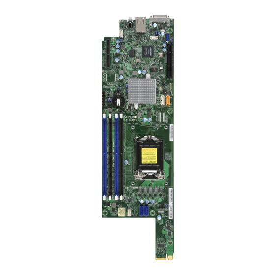
• Product safety info: http://www.supermicro.com/about/policies/safety_information.cfm • If you have any questions, please contact our support team at: support@supermicro.com This manual may be periodically updated without notice. Please check the Supermicro website for possible updates to the manual revision level. - Page 9 Chapter 1: Introduction Figure 1-1. X11SSD-F Motherboard Image Note: All graphics shown in this manual were based upon the latest PCB revision available at the time of publication of the manual. The motherboard you received may or may not look exactly the same as the graphics shown in this manual.
- Page 10 X11SSD-F User's Manual Figure 1-2. X11SSD-F Motherboard Layout (not drawn to scale) JIPMB1 JSTBY1 IPMI_LAN JSMB1 USB2(3.0) JPB1 LED3 JBT1 Intel C236 JSD1 JVR1 SATA DOM POWER I-SATA2 I-SATA3 JTPM1 SATA DOM+POWER X11SSD-F REV:1.00 DESIGNED IN USA CPU Socket LGA1151...
-
Page 11: Quick Reference
Intel JSD1 JWD1 C236 JSD1 JVR1 SATA DOM POWER JBR1 JTPM1 I-SATA3 I-SATA2 I-SATA3 JTPM1 SATA DOM+POWER JVRM2 I-SATA2 JVRM1 X11SSD-F REV:1.00 DESIGNED IN USA CPU Socket LGA1151 DIMMA1 DIMMA2 DIMMB1 DIMMB2 FAN1 S-SGPIO1 S-SGPIO1 FAN1 SAS0 SAS1 Notes: •... -
Page 12: Quick Reference Table
X11SSD-F User's Manual Quick Reference Table Jumper Description Default Setting JBR1 BIOS Recovery Pins 1-2 (Normal) JBT1 CMOS Clear Open (Normal) C1/JI SMB to PCI-E Slots Enable/Disable Both Open (Disabled) JPG1 VGA Enable/Disable Pins 1-2 (Enabled) JPME2 ME Manufacturing Mode... -
Page 13: Motherboard Features
DIMM Size • Up to 16GB at 1.2V Note 1: Memory speed support depends on the processors used in the system. Note 2: For the latest CPU/memory updates, please refer to our website at http://www.supermicro.com/products/ motherboard. Chipset • Intel® PCH C236 Expansion Slots •... - Page 14 Power button override mechanism • Power-on mode for AC power recovery • Intel® Intelligent Power Node Manager 3.0 (available when the Supermicro Power Manager [SPM] is installed and a special power supply is used. See the note on page 22.) • ACPI Management •...
- Page 15 CPU TDP sizing. Note 2: For IPMI configuration instructions, please refer to the Embedded IPMI Con- figuration User's Guide available at http://www.supermicro.com/support/manuals/. Note 3: It is strongly recommended that you change BMC log-in information upon ini- tial system power-on.
- Page 16 X11SSD-F User's Manual Figure 1-3. System Block Diagram SVID IMVP8 IMVP8 PCIe3.0_x8 PCIe x8 SLOT INTEL LGA1151 8.0GT/s DDR4 (CHA) PCIe3.0_x8 (Socket-H4) DIMMA0 PCIe x8 SLOT 2133/1866/1600MHz 8.0GT/s DIMMA1 Micro-LP DDR4 (CHB) DIMMB0 2133/1866/1600MHz DIMMB1 x4 DMI 8GT/s SATA-III 1 X SATA-III (DOM)
-
Page 17: Processor And Chipset Overview
1.2 Processor and Chipset Overview Built upon the functionality and capability of the Intel® E3-1200 v5 series processors (Socket LGA 1151) and the Intel C236 PCH, the X11SSD-F motherboard offers maximum I/O expendability, energy efficiency, and data reliability in a 14-nm process architecture, and is optimized for embedded storage solutions, networking applications, or cloud-computing platforms. -
Page 18: System Health Monitoring
X11SSD-F User's Manual 1.4 System Health Monitoring This section describes the health monitoring features of the X11SSD-F motherboard. The motherboard has an onboard Baseboard Management Controller (BMC) chip that supports system health monitoring. Once a voltage becomes unstable, a warning is given or an error message is sent to the screen. -
Page 19: Power Supply
Chapter 1: Introduction In addition to enabling operating system-directed power management, ACPI also provides a generic system event mechanism for Plug and Play and an operating system-independent interface for configuration control. ACPI leverages the Plug and Play BIOS data structures while providing a processor architecture-independent implementation that is compatible with Windows 8/R2, and Windows 2012/R2 operating systems. -
Page 20: Advanced Power Management
Intelligent Power Node Manager (IPNM) ® Available when the Supermicro Power Manager (SPM) is installed, Intel's Intelligent Power Node Manager (IPNM) provides your system with real-time thermal control and power management for maximum energy efficiency. Although IPNM Specification Version 2.0/3.0 is supported by the BMC (Baseboard Management Controller), your system must also have IPNM-compatible Management Engine (ME) firmware installed to use this feature. -
Page 21: Chapter 2 Installation
Chapter 2: Installation Chapter 2 Installation 2.1 Static-Sensitive Devices Electrostatic Discharge (ESD) can damage electronic com ponents. To prevent damage to your motherboard, it is important to handle it very carefully. The following measures are generally sufficient to protect your equipment from ESD. Precautions •... -
Page 22: Motherboard Installation
X11SSD-F User's Manual 2.2 Motherboard Installation All motherboards have standard mounting holes to fit different types of chassis. Make sure that the locations of all the mounting holes for both the motherboard and the chassis match. Although a chassis may have both plastic and metal mounting fasteners, metal ones are highly recommended because they ground the motherboard to the chassis. -
Page 23: Motherboard Installation
Chapter 2: Installation Motherboard Installation 1. Locate the mounting holes on the motherboard. See the previous page for the location. 2. Locate the matching mounting holes on the motherboard mounting tray. Install the standoffs. Align the mounting holes on the motherboard against the mounting holes on the motherboard tray. -
Page 24: Processor And Heatsink Installation
CPU socket cap is in place and none of the socket pins are bent; otherwise, contact your retailer immediately. • Refer to the Supermicro website for updates on CPU support. Installing the LGA1151 Processor 1. Press the load lever to release the load plate, which covers the CPU socket, from its locking position. - Page 25 Chapter 2: Installation 2. Gently lift the load lever to open the load plate. Remove the plastic cap. 3. Use your thumb and your index finger to hold the CPU at the north center edge and the South center edge of the CPU. North Center Edge South Center Edge 4.
- Page 26 X11SSD-F User's Manual 5. Do not rub the CPU against the surface or against any pins of the socket to avoid damaging the CPU or the socket. 6. With the CPU inside the socket, inspect the four corners of the CPU to make sure that the CPU is properly installed.
-
Page 27: Installing A Passive Cpu Heatsink
Chapter 2: Installation Installing a Passive CPU Heatsink 1. Do not apply any thermal grease to the heatsink or the CPU die -- the required amount has already been applied. 2. Place the heatsink on top of the CPU so that the four mounting holes are aligned with those on the Motherboard's and the Heatsink Bracket underneath. -
Page 28: Removing The Heatsink
X11SSD-F User's Manual Removing the Heatsink Note: We do not recommend that the CPU or the heatsink be removed. However, if you do need to uninstall the heatsink, please follow the instructions below to uninstall the heatsink to prevent damage done to the CPU or the CPU socket. -
Page 29: Memory Support And Installation
Memory Support The X11SSD-F supports up to 64 GB of DDR4 ECC VLP UDIMM memory up to 2133MHz in four memory slots. Populating these DIMM modules with a pair of memory modules of the same type and size will result in interleaved memory, which will improve memory performance. -
Page 30: Dimm Installation
X11SSD-F User's Manual DIMM Installation JIPMB1 1. Insert DIMM modules in the following JSTBY1 IPMI_LAN JSMB1 USB2(3.0) order: DIMMB2, DIMMA2, then DIMMB1, JPB1 DIMMA1. For the system to work properly, LED3 please use memory modules of the same JBT1 type and speed on the motherboard. -
Page 31: Rear I/O Ports
JPB1 LED3 JBT1 Intel C236 JSD1 JVR1 SATA DOM POWER I-SATA2 I-SATA3 JTPM1 SATA DOM+POWER X11SSD-F REV:1.00 DESIGNED IN USA CPU Socket LGA1151 FAN1 S-SGPIO1 Figure 2-2. I/O Port Locations and Definitions Rear I/O Ports Description KVM Port IPMI Port... - Page 32 X11SSD-F User's Manual KVM Port The KVM port supports two USB connections, a VGA and UART interface. Please attach a compatible KVM connector/switch to this port. IPMI LAN Port A dedicated IPMI LAN port is located next to the KVM port to provide a dedicated network connection for IPMI 2.0.
-
Page 33: Headers And Connectors
JSMB1 USB2(3.0) JPB1 LED3 1. USB2 - USB 3.0 Type A (Reserved) JBT1 2. USB Ports via KVM Intel C236 JSD1 JVR1 SATA DOM POWER I-SATA2 I-SATA3 JTPM1 SATA DOM+POWER X11SSD-F REV:1.00 DESIGNED IN USA CPU Socket LGA1151 FAN1 S-SGPIO1... - Page 34 X11SSD-F User's Manual Fan Header There is one fan header on the motherboard. This is a 4-pin fan headers; pins 1-3 are backward compatible with traditional 3-pin fans. The onboard fan speeds are controlled by Thermal Management (via Hardware Monitoring) in the BIOS. When using Thermal Management setting, please use all 3-pin fans or all 4-pin fans.
- Page 35 SMB_DAT4 (X) P3V3_STBY SERIRQ P3V3_STBY LDRQ# (X) 1. TPM Header JIPMB1 JSTBY1 IPMI_LAN JSMB1 USB2(3.0) JPB1 LED3 JBT1 Intel C236 JSD1 JVR1 SATA DOM POWER I-SATA2 I-SATA3 JTPM1 SATA DOM+POWER X11SSD-F REV:1.00 DESIGNED IN USA CPU Socket LGA1151 FAN1 S-SGPIO1...
- Page 36 X11SSD-F User's Manual System Management Bus A System Management Bus header for the IPMI slot is located at JIPMB1. Connect the appropriate cable here to use the IPMB I2C connection on your system. System Management Pin Definitions Pin# Definition Data...
- Page 37 (Yellow, +3V3SB JPB1 TD2+ Ground TD2- Ground LED3 TD3+ Ground JBT1 TD3- Ground Intel C236 JSD1 JVR1 SATA DOM POWER JTPM1 I-SATA2 I-SATA3 SATA DOM+POWER 1. SGPIO Header X11SSD-F REV:1.00 DESIGNED IN USA 2. IPMI_LAN Port CPU Socket LGA1151 FAN1 S-SGPIO1...
- Page 38 X11SSD-F User's Manual SATA and SAS Ports The X11SSD-F has two SATA 3.0 ports (I-SATA2 and I-SATA3) and two SAS 3.0 ports SAS0 and SAS1) that are supported by the Intel PCH C236 chipset. SATA 3.0 Port Pin Definitions Pin#...
-
Page 39: Jumper Settings
Chapter 2: Installation 2.8 Jumper Settings How Jumpers Work To modify the operation of the motherboard, jumpers can be used to choose between optional settings. Jumpers create shorts between two pins to change the function of the connector. Pin 1 is identified with a square solder pad on the printed circuit board. See the diagram at right for an example of jumping pins 1 and 2. - Page 40 X11SSD-F User's Manual SMBus to PCI Slots Jumpers JI C1 and JI C2 allow you to connect the System Management Bus (I C) to the PCI-E/PCI slots. The default setting is Open (Disabled.) Both jumpers must be set to the...
- Page 41 Definition Normal (Default) Recover 1. VGA Enable JIPMB1 2. BIOS Recovery JSTBY1 IPMI_LAN JSMB1 USB2(3.0) JPB1 LED3 JBT1 Intel C236 JSD1 JVR1 SATA DOM POWER I-SATA2 I-SATA3 JTPM1 SATA DOM+POWER X11SSD-F REV:1.00 DESIGNED IN USA CPU Socket LGA1151 FAN1 S-SGPIO1...
- Page 42 X11SSD-F User's Manual I2C Bus for VRM Jumpers JVRM1 and JVRM2 allow the BMC or the PCH to access CPU and memory VRM controllers. Refer to the table below for jumper settings. Jumper Settings Jumper Setting Definition Pins 1-2 BMC (Default)
- Page 43 Pins 2-3 SAS1 JIPMB1 JSTBY1 IPMI_LAN JSMB1 USB2(3.0) JPB1 LED3 1. BMC Enable JBT1 Intel 2. Storage Type Configuration C236 JSD1 JVR1 SATA DOM POWER I-SATA2 I-SATA3 JTPM1 SATA DOM+POWER X11SSD-F REV:1.00 DESIGNED IN USA CPU Socket LGA1151 FAN1 S-SGPIO1...
-
Page 44: Led Indicators
X11SSD-F User's Manual 2.9 LED Indicators IPMI_LAN LED The yellow LED on the right indicates activity, while the green/amber LED on the left indicates the speed of the connection. Refer to the table below for more inofrmation. IPMI LAN LED... - Page 45 Blinking 1. Overheat/PWR Fail/Fan Fail LED JIPMB1 JSTBY1 IPMI_LAN 2. BMC Heartbeat LED JSMB1 USB2(3.0) JPB1 LED3 JBT1 Intel C236 JSD1 JVR1 SATA DOM POWER I-SATA2 I-SATA3 JTPM1 SATA DOM+POWER X11SSD-F REV:1.00 DESIGNED IN USA CPU Socket LGA1151 FAN1 S-SGPIO1...
- Page 46 X11SSD-F User's Manual UID LED Indicator The UID LED Indicator located LED1 is next to the UID Button. When you press the UID Button, the UID LED Indicator will turn on. Press the UID Button again to turn off the UID LED Indicator.
-
Page 47: Chapter 3 Troubleshooting
Chapter 3: Troubleshooting Chapter 3 Troubleshooting 3.1 Troubleshooting Procedures Use the following procedures to troubleshoot your system. If you have followed all of the procedures below and still need assistance, refer to the ‘Technical Support Procedures’ and/ or ‘Returning Merchandise for Service’ section(s) in this chapter. Always disconnect the AC power cord before adding, changing or installing any non hot-swap hardware components. -
Page 48: No Video
X11SSD-F User's Manual No Video 1. If the power is on but you have no video, remove all the add-on cards and cables. 2. Use the speaker to determine if any beep codes exist. Refer to Appendix A for details on beep codes. -
Page 49: Losing The System's Setup Configuration
2. Memory support: Make sure that the memory modules are supported by testing the modules using memtest86 or a similar utility. Note: Refer to the product page on our website at http:\\www.supermicro.com for memory and CPU support and updates. 3. HDD support: Make sure that all hard disk drives (HDDs) work properly. Replace the bad HDDs with good ones. - Page 50 X11SSD-F User's Manual 3. Using the minimum configuration for troubleshooting: Remove all unnecessary components (starting with add-on cards first), and use the minimum configuration (but with a CPU and a memory module installed) to identify the trouble areas. Refer to the steps listed in Section A above for proper troubleshooting procedures.
-
Page 51: Technical Support Procedures
Chapter 3: Troubleshooting 3.2 Technical Support Procedures Before contacting Technical Support, please take the following steps. Also, note that as a motherboard manufacturer, we do not sell directly to end-users, so it is best to first check with your distributor or reseller for troubleshooting services. They should know of any possible problem(s) with the specific system configuration that was sold to you. -
Page 52: Frequently Asked Questions
3.3 Frequently Asked Questions Question: What type of memory does my motherboard support? Answer: The X11SSD-F motherboard supports up to 64 GB of DDR4 ECC VLP UDIMM memory up to 2133MHz. See Section 2.4 for details on installing memory. Question: How do I update my BIOS? Answer: It is recommended that you do not upgrade your BIOS if you are not experiencing any problems with your system. -
Page 53: Battery Removal And Installation
Chapter 3: Troubleshooting 3.4 Battery Removal and Installation Battery Removal To remove the onboard battery, follow the steps below: 1. Power off your system and unplug your power cable. 2. Locate the onboard battery as shown below. 3. Using a tool such as a pen or a small screwdriver, push the battery lock outwards to unlock it. -
Page 54: Returning Merchandise For Service
X11SSD-F User's Manual 3.5 Returning Merchandise for Service A receipt or copy of your invoice marked with the date of purchase is required before any warranty service will be rendered. You can obtain service by calling your vendor for a Returned Merchandise Authorization (RMA) number. -
Page 55: Chapter 4 Bios
BIOS 4.1 Introduction This chapter describes the AMIBIOS™ Setup utility for the X11SSD-F motherboard. The BIOS is stored on a chip and can be easily upgraded using a flash program. Note: Due to periodic changes to the BIOS, some settings may have been added or deleted and might not yet be recorded in this manual. -
Page 56: Main Setup
X11SSD-F User's Manual 4.2 Main Setup When you first enter the AMI BIOS setup utility, you will enter the Main setup screen. You can always return to the Main setup screen by selecting the Main tab on the top of the screen. The Main BIOS setup screen is shown below. - Page 57 Chapter 4: BIOS Memory Information Total Memory This item displays the total size of memory available in the system. Memory Speed This item displays the memory speed.
-
Page 58: Advanced Setup Configurations
X11SSD-F User's Manual 4.3 Advanced Setup Configurations Use the arrow keys to select Boot Setup and press <Enter> to access the submenu items. Warning: Take caution when changing the Advanced settings. An incorrect value, a very high DRAM frequency, or an incorrect DRAM timing setting may make the system unstable. When this occurs, revert to the default to the manufacture default settings. - Page 59 Chapter 4: BIOS Wait For 'F1' If Error Use this feature to force the system to wait until the 'F1' key is pressed if an error occurs. The options are Disabled and Enabled. INT19 (Interrupt 19) Trap Response Interrupt 19 is the software interrupt that handles the boot disk function. When this item is set to Immediate, the ROM BIOS of the host adaptors will "capture"...
- Page 60 X11SSD-F User's Manual CPU Configuration The following CPU information will display: • Type of CPU • CPU Signature • Microcode Patch • Max CPU Speed • Min CPU Speed • CPU Speed • Processor Cores • Hyper Threading Technology •...
- Page 61 Chapter 4: BIOS Active Processor Cores This feature determines how many CPU cores will be activated for each CPU. When all is selected, all cores in the CPU will be activated. (Please refer to Intel's website for more information.) The options are All and 1, 2, and 3. Intel ®...
- Page 62 X11SSD-F User's Manual Package Power Limit MSR Lock Select Enabled to lock the package power limit for the model specific registers. The options are Disabled and Enabled. Power Limit 1 Override Select Enabled to support average power limit (PL1) override. The default setting is Disabled.
- Page 63 Chapter 4: BIOS C-State Auto Demotion Use this feature to prevent unnecessary excursions into the C-states to improve latency. The options are Disabled, C1, C3, and C1 and C3. C-State Un-Demotion This feature allows the user to enable or disable the un-demotion of C-State. The options are Disabled, C1, C3, and C1 and C3 Package C-State Demotion Use this feature to enable or disable the Package C-State demotion.
- Page 64 X11SSD-F User's Manual Chipset Configuration Warning: Setting the wrong values in the following features may cause the system to malfunc- tion. System Agent (SA) Configuration The following System Agent information will display: • System Agent Bridge Name • SA PCIe Code Version •...
- Page 65 Chapter 4: BIOS Primary PEG This feature allows the user to select the primary PCI Express Graphics (PEG) slot. The options are CPU1 SLOT1 PCI-E 3.0 X8 and CPU1 MICRO-LP PCI-E 3.0 X8. Primary PCIE (PCI-Express Graphics) This feature allows the user to specify which graphics card to be used as the primary graphics card.
- Page 66 X11SSD-F User's Manual PEG Port Configuration CPU1 SLOT1 PCI-E 3.0 X8 SLOT1 Max Link Speed Use this item to configure the link speed of a PCI-E port specified by the user. The options are Auto, Gen1, Gen2, and Gen3. SLOT1 Max Payload Size Select Auto for the system BIOS to automatically set the maximum payload value for a PCI-E device to enhance system performance.
- Page 67 Chapter 4: BIOS MICRO-LP Slot Power Limit Value Use this feature to set the upper limit on the power supplied by the PCIE slot. Press "+" or "-" on your keyboard to change this value. The default setting is 75. MICRO-LP Slot Power Limit Scale Use this feature to select the scale used for the slot power limit value.
- Page 68 X11SSD-F User's Manual Energy Performance Gain Use this feature to enable or disable the energy performance gain. The options are Disabled and Enabled. Memory Scrambler Select Enabled to enable memory scrambler support. The options are Disabled and Enabled. Fast Boot Use this feature to enable or disable fast path through the memory reference code.
- Page 69 Chapter 4: BIOS PCIe PLL SSC Enable this feature to reduce EMI interference by down spreading clock 0.5%. Disable this feature to centralize the clock without spreading. The options are Disabled and Enabled. SATA Configuration When this submenu is selected, the AMI BIOS automatically detects the presence of the SATA devices that are supported by the Intel PCH chip and displays the following items: SATA Controller(s) This item enables or disables the onboard SATA controller supported by the Intel PCH chip.
- Page 70 X11SSD-F User's Manual Port 0 ~ Port 3 SATA Device Type Use this item to specify if the SATA port specified by the user should be connected to a Solid State drive or a Hard Disk Drive. The options are Hard Disk Drive and Solid State Drive.
- Page 71 Chapter 4: BIOS Network Stack Select Enabled to enable PXE (Preboot Execution Environment) or UEFI (Unified Extensible Firmware Interface) for network stack support. The options are Enabled and Disabled. IPv4 PXE Support Select Enabled to enable IPv4 PXE boot support. The options are Enabled and Disabled. IPv6 PXE Support Select Enabled to enable IPv6 PXE boot support.
- Page 72 X11SSD-F User's Manual SOL Configuration This submenu allows the user the configure settings of SOL. SOL Configuration Select Enabled to enable the selected onboard serial port. The options are Enabled and Disabled. Device Settings This item displays the status of a serial part specified by the user.
- Page 73 Chapter 4: BIOS Serial Port Console Redirection COM1 Console Redirection Console Redirection Select Enabled to enable console redirection support for a serial port specified by the user. The options are Enabled and Disabled. *If the item above set to Enabled, the following items will become available for user's configuration: COM1 Console Redirection Settings This feature allows the user to specify how the host computer will exchange data with the...
- Page 74 X11SSD-F User's Manual COM1 Flow Control Use this feature to set the flow control for Console Redirection to prevent data loss caused by buffer overflow. Send a "Stop" signal to stop sending data when the receiving buffer is full. Send a "Start" signal to start sending data when the receiving buffer is empty. The options are None and Hardware RTS/CTS.
- Page 75 Chapter 4: BIOS SOL Console Redirection Settings Use this feature to specify how the host computer will exchange data with the client computer, which is the remote computer used by the user. SOL Terminal Type Use this feature to select the target terminal emulation type for Console Redirection. Select VT100 to use the ASCII Character set.
- Page 76 X11SSD-F User's Manual SOL Recorder Mode Select Enabled to capture the data displayed on a terminal and send it as text messages to a remote server. The options are Disabled and Enabled. SOL Resolution 100x31 Select Enabled for extended-terminal resolution support. The options are Disabled and Enabled.
- Page 77 Chapter 4: BIOS Terminal Type Use this feature to select the target terminal emulation type for Console Redirection. Select VT100 to use the ASCII character set. Select VT100+ to add color and function key support. Select ANSI to use the extended ASCII character set. Select VT-UTF8 to use UTF8 encoding to map Unicode characters into one or more bytes.
- Page 78 X11SSD-F User's Manual Trusted Computing Configuration Security Device Support If this feature and the TPM jumper on the motherboard are both set to Enabled, onbaord security devices will be enabled for TPM (Trusted Platform Module) support to enhance data integrity and network security.
- Page 79 Chapter 4: BIOS Hash Policy Use this item to select which hash policy to use. SHA-1 is the most secured, but it may not be supported by all operating systems. The options are Sha-1 and Sha256. Device Select Use this feature to select the TPM version. TPM 1.2 will restrict support to TPM 1.2 devices. TPM 2.0 will restrict support for TPM 2.0 devices.
-
Page 80: Event Logs
X11SSD-F User's Manual 4.4 Event Logs Use this feature to configure Event Log settings. Change SMBIOS Event Log Settings Enabling/Disabling Options SMBIOS Event Log Change this item to enable or disable all features of the SMBIOS Event Logging during system boot. - Page 81 Chapter 4: BIOS SMBIOS Event Long Standard Settings Log System Boot Event This option toggles the System Boot Event logging to enabled or disabled. The options are Disabled and Enabled. MECI The Multiple Event Count Increment (MECI) counter counts the number of occurences that a duplicate event must happen before the MECI counter is incremented.
-
Page 82: Ipmi
X11SSD-F User's Manual 4.5 IPMI Use this feature to configure Intelligent Platform Management Interface (IPMI) settings. BMC Firmware Revision This item indicates the IPMI firmware revision used in your system. IPMI Status (Baseboard Management Controller) This item indicates the status of the IPMI firmware installed in your system. - Page 83 Chapter 4: BIOS When SEL is Full This feature allows the user to decide what the BIOS should do when the system event log is full. Select Erase Immediately to erase all events in the log when the system event log is full.
- Page 84 X11SSD-F User's Manual Station MAC Address This item displays the Station MAC address for this computer. Mac addresses are 6 two-digit hexadecimal numbers. Gateway IP Address This item displays the Gateway IP address for this computer. This should be in decimal and in dotted quad form (i.e., 172.31.0.1).
-
Page 85: Security
Chapter 4: BIOS 4.6 Security This menu allows the user to configure the following security settings for the system. Password Check Select Setup for the system to check for a password at Setup. Select Always for the system to check for a password at bootup or upon entering the BIOS Setup utility. The options are Setup and Always. - Page 86 X11SSD-F User's Manual Secure Boot Mode Use this item to select the secure boot mode. The options are Standard and Custom. CSM Support Select Enabled to support the EFI Compatibility Support Module (CSM), which provides compatibility support for traditional legacy BIOS for system boot. The options are Enabled and Disabled.
- Page 87 Chapter 4: BIOS Append Key Select Yes to add the database from the manufacturer's defaults to the existing DB. Select No to load the DB from a file. The options are Yes and No. Forbiden Signatures Set New Key Select Yes to load the DBX from the manufacturer's defaults.
-
Page 88: Boot
X11SSD-F User's Manual 4.7 Boot Use this feature to configure Boot Settings: Boot Mode Select Use this item to select the type of device that the system is going to boot from. The options are Legacy, UEFI, and Dual. The default setting is Dual. - Page 89 Chapter 4: BIOS • Legacy/UEFI/Dual/Boot Option #8 • Legacy/UEFI/Dual/Boot Option #9 • Legacy/UEFI/Dual/Boot Option #10 • Legacy/UEFI/Dual/Boot Option #11 • Legacy/UEFI/Dual/Boot Option #12 • Legacy/UEFI/Dual/Boot Option #13 • Legacy/UEFI/Dual/Boot Option #14 • Legacy/UEFI/Dual/Boot Option #15 Delete Boot Option Use this feature to remove a pre-defined boot device from which the system will boot during startup.
-
Page 90: Save & Exit
X11SSD-F User's Manual 4.8 Save & Exit Select the Exit tab from the BIOS setup utility screen to enter the Exit BIOS Setup screen. Discard Changes and Exit Select this option to quit the BIOS Setup without making any permanent changes to the system configuration, and reboot the computer. - Page 91 Chapter 4: BIOS Default Options Restore Optimized Defaults To set this feature, select Restore Optimized Defaults from the Save & Exit menu and press <Enter>. These are factory settings designed for maximum system stability, but not for maximum performance. Save As User Defaults To set this feature, select Save as User Defaults from the Exit menu and press <Enter>.
-
Page 92: Appendix A Bios Codes
X11SSD-F User's Manual Appendix A BIOS Codes A.1 BIOS Error POST (Beep) Codes During the POST (Power-On Self-Test) routines, which are performed each time the system is powered on, errors may occur. Non-fatal errors are those which, in most cases, allow the system to continue the boot-up process. - Page 93 When BIOS performs the Power On Self Test, it writes checkpoint codes to I/O port 0080h. If the computer cannot complete the boot process, a diagnostic card can be attached to the computer to read I/O port 0080h (Supermicro p/n AOC-LPC80-20). For information on AMI updates, please refer to http://www.ami.com/products/.
-
Page 94: Appendix B Software Installation
Appendix B Software Installation B.1 Installing Software Programs The Supermicro FTP site contains drivers and utilities for your system at ftp://ftp.supermicro. com. Some of these must be installed, such as the chipset driver. After accessing the FTP site, go into the CDR_Images directory and locate the ISO file for your motherboard. -
Page 95: Superdoctor ® 5
SATA settings back to your original settings. B.2 SuperDoctor ® The Supermicro SuperDoctor 5 is a hardware monitoring program that functions in a command-line or web-based interface in Windows and Linux operating systems. The program monitors system health information such as CPU temperature, system voltages, system power consumption, fan speed, and provides alerts via email or Simple Network Management Protocol (SNMP). -
Page 96: Appendix C Standardized Warning Statements
The following statements are industry standard warnings, provided to warn the user of situations which have the potential for bodily injury. Should you have questions or experience difficulty, contact Supermicro's Technical Support department for assistance. Only certified technicians should attempt to install or configure components. - Page 97 Appendix C: Warning Statements Attention Danger d'explosion si la pile n'est pas remplacée correctement. Ne la remplacer que par une pile de type semblable ou équivalent, recommandée par le fabricant. Jeter les piles usagées conformément aux instructions du fabricant. ¡Advertencia! Existe peligro de explosión si la batería se reemplaza de manera incorrecta.
-
Page 98: Product Disposal
X11SSD-F User's Manual Product Disposal Warning! Ultimate disposal of this product should be handled according to all national laws and regulations. 製品の廃棄 この製品を廃棄処分する場合、 国の関係する全ての法律 ・ 条例に従い処理する必要があります。 警告 本产品的废弃处理应根据所有国家的法律和规章进行。 警告 本產品的廢棄處理應根據所有國家的法律和規章進行。 Warnung Die Entsorgung dieses Produkts sollte gemäß allen Bestimmungen und Gesetzen des Landes erfolgen. -
Page 99: Appendix D Uefi Bios Recovery
Warning: Do not upgrade the BIOS unless your system has a BIOS-related issue. Flashing the wrong BIOS can cause irreparable damage to the system. In no event shall Supermicro be liable for direct, indirect, special, incidental, or consequential damages arising from a BIOS update. - Page 100 X11SSD-F User's Manual minutes to locate the SUPER.ROM file if the media size becomes too large because it contains too many folders and files. To perform UEFI BIOS recovery using a USB-attached device, follow the instructions below. 1. Using a different system, copy the "Super.ROM" binary image file into the disc Root "\"...
- Page 101 Appendix D: UEFI BIOS Recovery 4. After locating the new BIOS binary image, the system will enter the BIOS Recovery menu as shown below. Note: At this point, you may decide if you want to start the BIOS recovery. If you decide to proceed with BIOS recovery, follow the procedures below.
- Page 102 X11SSD-F User's Manual 6. After the BIOS recovery process has completed, press any key to reboot the system. 7. Using a different system, extract the BIOS package into a bootable USB flash drive. 8. When a DOS prompt appears, enter FLASH.BAT BIOSname.### at the prompt.
Need help?
Do you have a question about the X11SSD-F and is the answer not in the manual?
Questions and answers