Table of Contents
Advertisement
Quick Links
Advertisement
Table of Contents

Related Manuals for Supermicro X11SSW-F


Summary of Contents for Supermicro X11SSW-F
- Page 1 X11SSW-F USER MANUAL Revision 1.1...
- Page 2 State of California, USA. The State of California, County of Santa Clara shall be the exclusive venue for the resolution of any such disputes. Supermicro's total liability for all claims will not exceed the price paid for the hardware product.
- Page 3 It provides information for the installation and use of the X11SSW-F motherboard. About This Motherboard The Super X11SSW-F motherboard supports an Intel® Xeon E3-1200 v5, 6th-Gen Core i3, Pentium, or Celeron processor in an LGA 1151 (H4) socket. With support of the Intel C236 chipset, DDR4 2400MHz memory, SATA 3.0, PCIe 3.0, M.2 and Trusted Platform Module...
- Page 4 X11SSW-F User Manual Contacting Supermicro Headquarters Address: Super Micro Computer, Inc. 980 Rock Ave. San Jose, CA 95131 U.S.A. Tel: +1 (408) 503-8000 Fax: +1 (408) 503-8008 Email: marketing@supermicro.com (General Information) support@supermicro.com (Technical Support) Website: www.supermicro.com Europe Address: Super Micro Computer B.V.
-
Page 5: Table Of Contents
Preface Table of Contents Chapter 1 Introduction 1.1 Checklist ..........................8 Quick Reference .......................11 Quick Reference Table ......................12 Motherboard Features .......................14 1.2 Processor and Chipset Overview ..................18 1.3 Special Features ........................18 Recovery from AC Power Loss ..................18 1.4 System Health Monitoring ....................19 Onboard Voltage Monitors ....................19 Fan Status Monitor with Firmware Control ...............19 Environmental Temperature Control .................19... - Page 6 X11SSW-F User Manual DIMM Module Population Sequence ................31 DIMM Installation ......................32 DIMM Removal .........................32 2.5 Rear I/O Ports ........................33 2.6 Front Control Panel ......................38 2.7 Connectors .........................43 Power Connections ......................43 Headers ..........................45 2.8 Jumper Settings .........................56 How Jumpers Work ......................56 2.9 LED Indicators ........................62...
- Page 7 4.5 IPMI ..........................102 4.6 Security ..........................105 4.7 Boot ..........................108 4.8 Save & Exit ........................110 Appendix A BIOS Codes Appendix B Software Installation B.1 Installing Software Programs ...................113 Appendix C Standardized Warning Statements Battery Handling ......................115 Product Disposal ......................117 Appendix D UEFI BIOS Recovery Appendix E Dual Boot Block BIOS Boot Block ......................122 BIOS Boot Block Corruption Occurrence ..............122...
-
Page 8: Chapter 1 Introduction
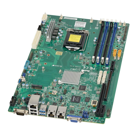
• Product safety info: http://www.supermicro.com/about/policies/safety_information.cfm • If you have any questions, please contact our support team at: support@supermicro.com This manual may be periodically updated without notice. Please check the Supermicro website for possible updates to the manual revision level. - Page 9 Chapter 1: Introduction Figure 1-1. X11SSW-F Motherboard Image Note: All graphics shown in this manual were based upon the latest PCB revision available at the time of publication of the manual. The motherboard you received may or may not look exactly the same as the graphics shown in this manual.
- Page 10 X11SSW-F User Manual Figure 1-2. X11SSW-F Motherboard Layout (not drawn to scale) COM1 LAN2 LAN1 USB6/7 USB0/1 JUIDB1 (3.0) JI2C1 IPMI_LAN SRW4 JPL1 LEDBMC LEDEC1 JBT1 JIPMB1 JSTBY1 Intel PCH SRW2 2260 X11SSW-F SRW3 REV:1.01 Designed in the USA 2280...
-
Page 11: Quick Reference
LEDEC1 LEDEC1 JBT1 JIPMB1 JBT1 JIPMB1 I-SATA7 JSTBY1 JSTBY1 JSXB1B I-SATA6 Intel PCH USB4/5 SRW2 I-SATA4 2260 USB9/10 X11SSW-F SRW3 REV:1.01 I-SATA5 Designed in the USA 2280 JSXB1C JTPM1 SRW1 JSD2 DIMMA1 JTPM1 22110 BIOS DIMMA2 JSD1 JSD2 LICENSE JSD1... -
Page 12: Quick Reference Table
X11SSW-F User Manual Quick Reference Table Jumper Description Default Setting JBR1 BIOS Recovery Pins 1-2 (Normal) JBT1 Clear CMOS See Chapter 2 JI2C1/JI2C2 SMB to PCI Slots Pins 2-3 (Disabled) JPB1 BMC Enable/Disable Pins 1-2 (Enabled) JPG1 VGA Enable Pins 1-2 (Enabled) - Page 13 Chapter 1: Introduction Connector Description JUIDB1 UID (Unit Identification) Switch LAN1/LAN2 Gigabit (RJ45) LAN Ports Internal Speaker/Buzzer USB 0/1 Back Panel USB 2.0 Ports USB 2/3, USB 4/5 Front Accessible USB 2.0 Headers USB 6/7 Back Panel USB 3.0 Ports USB 8 USB 3.0 Type-A Header USB 9/10...
-
Page 14: Motherboard Features
• 16GB, 8GB, and 4GB, up to 64GB at 1.2V Note 1: Memory speed support depends on the processors used in the system. Note 2: For the latest CPU/memory updates, please refer to our website at http://www.supermicro.com/products/ motherboard. Chipset •... - Page 15 Chapter 1: Introduction Motherboard Features Peripheral Devices • Two (2) USB 2.0 ports on the rear I/O panel (USB 0/1) • Two (2) front accessible USB 2.0 headers (USB 2/3, 4/5) • Two (2) USB 3.0 ports on the rear I/O panel (USB 6/7) •...
- Page 16 Note 1: The CPU maximum thermal design power (TDP) is subject to chassis and heatsink cooling restrictions. For proper thermal management, please check the chas- sis and heatsink specifications for proper CPU TDP sizing. Note 2: For IPMI configuration instructions, please refer to the Embedded IPMI Con- figuration User's Guide available at http://www.supermicro.com/support/manuals/.
- Page 17 Chapter 1: Introduction Figure 1-3. System Block Diagram IMVP 8 3 PHASE for Vcore #B-2 1 PHASE for VSA #B-1 #A-2 #A-1 PCI-E X16 8.0 Gb/S Skt-H4 SXB1 PCIe 3.0 x16 #0-15 LGA1151 DMI3 DMI3 x4 PCI-E X4 8.0 Gb/S PCIe3.0 x4 (in x8) SXB2 #5/6/7/8...
-
Page 18: Processor And Chipset Overview
1.2 Processor and Chipset Overview Built upon the functionality and capability of the Intel E3-1200 v5 series processors (Socket LGA 1151) and the Intel C236 PCH, the X11SSW-F motherboard offers maximum I/O expandability, energy efficiency, and data reliability in a 14-nm process architecture, and is optimized for embedded storage solutions, networking applications, or cloud-computing platforms. -
Page 19: System Health Monitoring
Chapter 1: Introduction 1.4 System Health Monitoring The motherboard has an onboard Baseboard Management Controller (BMC) chip that supports system health monitoring. Onboard Voltage Monitors The onboard voltage monitor will continuously scan crucial voltage levels. Once a voltage becomes unstable, it will give a warning or send an error message to the screen. Users can adjust the voltage thresholds to define the sensitivity of the voltage monitor. -
Page 20: Power Supply
1.7 Serial Port The X11SSW-F motherboard supports two serial communication connections. COM Ports 1 and 2 can be used for input/output. The UART provides legacy speeds with a baud rate of up to 115.2 Kbps as well as an advanced speed with baud rates of 250 K, 500 K, or 1 Mb/s,... -
Page 21: Chapter 2 Installation
Chapter 2: Installation Chapter 2 Installation 2.1 Static-Sensitive Devices Electrostatic Discharge (ESD) can damage electronic com ponents. To prevent damage to your motherboard, it is important to handle it very carefully. The following measures are generally sufficient to protect your equipment from ESD. Precautions •... -
Page 22: Motherboard Installation
X11SSW-F User Manual 2.2 Motherboard Installation All motherboards have standard mounting holes to fit different types of chassis. Make sure that the locations of all the mounting holes for both the motherboard and the chassis match. Although a chassis may have both plastic and metal mounting fasteners, metal ones are highly recommended because they ground the motherboard to the chassis. -
Page 23: Installing The Motherboard
Chapter 2: Installation Installing the Motherboard 1. Locate the mounting holes on the motherboard. See the previous page for the location. 2. Locate the matching mounting holes on the chassis. Align the mounting holes on the motherboard against the mounting holes on the chassis. 3. -
Page 24: Processor And Heatsink Installation
CPU socket cap is in place and none of the socket pins are bent; otherwise, contact your retailer immediately. • Refer to the Supermicro website for updates on CPU support. Installing the LGA1151 Processor 1. Press the load lever to release the load plate, which covers the CPU socket, from its locking position. - Page 25 Chapter 2: Installation 2. Gently lift the load lever to open the load plate. Remove the plastic cap. 3. Use your thumb and your index finger to hold the CPU at the North center edge and the South center edge of the CPU. North Center Edge South Center Edge 4.
- Page 26 X11SSW-F User Manual 5. Do not rub the CPU against the surface or against any pins of the socket to avoid damaging the CPU or the socket. 6. With the CPU inside the socket, inspect the four corners of the CPU to make sure that the CPU is properly installed.
-
Page 27: Installing An Active Cpu Heatsink With Fan
5. Apply the proper amount of thermal grease on the CPU. Note: If your heatsink came with a ther- mal pad, please ignore this step. Recommended Supermicro heatsink: 6. If necessary, rearrange the wires to SNK-P0046A4 or SNK-P0051AP4 active heatsink... - Page 28 X11SSW-F User Manual 7. Align the four heatsink fasteners with the mounting holes on the motherboard. Gently push the pairs of diagonal fasteners (#1 & #2, and #3 & #4) into the mounting holes until you hear a click. Also, make sure to orient each fastener so that the narrow end of the groove is pointing outward.
-
Page 29: Removing The Heatsink
Chapter 2: Installation Removing the Heatsink Note: We do not recommend that the CPU or the heatsink be removed. However, if you do need to remove the heatsink, please follow the instructions below to remove the heatsink and to prevent damage done to the CPU or other components. -
Page 30: Memory Support And Installation
Memory Support The X11SSW-F motherboard supports up to 64GB of unbuffered (UDIMM) DDR4 ECC 2400/2133/1866/1600/1333MHz memory in four memory slots. Populating these DIMM slots with memory modules of the same type and size will result in interleaved memory, which will improve memory performance. -
Page 31: Dimm Module Population Sequence
LAN1 JUIDB1 USB6/7 USB0/1 (3.0) JI2C1 IPMI_LAN SRW4 JPL1 LEDBMC LEDEC1 JBT1 JIPMB1 JSTBY1 Intel PCH SRW2 2260 X11SSW-F SRW3 REV:1.01 Designed in the USA 2280 SRW1 JTPM1 22110 BIOS JSD1 JSD2 LICENSE JOH1 JPI2C1 LEDPWR I-SGPIO2 JPWR1 I-SGPIO1 IPMI CODE... -
Page 32: Dimm Installation
X11SSW-F User Manual DIMM Installation COM1 JUIDB1 LAN2 LAN1 USB6/7 USB0/1 (3.0) JI2C1 1. Insert the desired number of DIMMs into IPMI_LAN the memory slots, starting with DIMMB2 SRW4 JPL1 LEDBMC (Channel B, Slot 2, blue slot). For best LEDEC1... -
Page 33: Rear I/O Ports
LAN1 USB6/7 JUIDB1 USB0/1 (3.0) JI2C1 IPMI_LAN SRW4 JPL1 LEDBMC LEDEC1 JBT1 JIPMB1 JSTBY1 Intel PCH SRW2 2260 X11SSW-F SRW3 REV:1.01 Designed in the USA 2280 SRW1 JTPM1 22110 BIOS JSD1 JSD2 LICENSE JOH1 JPI2C1 LEDPWR I-SGPIO2 JPWR1 I-SGPIO1 IPMI CODE... - Page 34 X11SSW-F User Manual VGA Port A video (VGA) port is located next to LAN2 on the I/O back panel. Refer to the board layout below for the location. Serial Ports Two COM connections (COM1 & COM2) are located on the motherboard. COM1 is located on the I/O back panel.
- Page 35 Chapter 2: Installation Universal Serial Bus (USB) Ports There are two USB 2.0 ports (USB0/1) and two USB 3.0 ports (USB6/7) located on the I/O back panel. The motherboard also has two front access USB 2.0 headers (USB2/3 and USB4/5) and one front access USB 3.0 header (USB9/10). The USB8 header is USB 3.0 Type A.
- Page 36 X11SSW-F User Manual Type A USB 8 (3.0) Pin Definitions Pin# Definition Pin# Definition VBUS SSRX- USB_N SSRX+ USB_P Ground SSTX- SSTX+ Front Panel USB 9/10 (3.0) Pin Definitions Pin# Definition Pin# Definition VBUS Power USB_N USB_P Stda_SSRX- USB3_RN Stda_SSRX+...
- Page 37 1. LAN1 (3.0) JI2C1 2. LAN2 IPMI_LAN 3. IPMI LAN SRW4 JPL1 LEDBMC LEDEC1 JBT1 JIPMB1 JSTBY1 Intel PCH SRW2 2260 X11SSW-F SRW3 REV:1.01 Designed in the USA 2280 SRW1 JTPM1 22110 BIOS JSD1 JSD2 LICENSE JOH1 JPI2C1 LEDPWR I-SGPIO2 JPWR1...
-
Page 38: Front Control Panel
JF1 contains header pins for various buttons and indicators that are normally located on a control panel at the front of the chassis. These connectors are designed specifically for use with Supermicro chassis. See the figure below for the descriptions of the front control panel buttons and LED indicators. - Page 39 Chapter 2: Installation Power Button The Power Button connection is located on pins 1 and 2 of JF1. Momentarily contacting both pins will power on/off the system. This button can also be configured to function as a suspend button (with a setting in the BIOS - see Chapter 4). To turn off the power when the system is in suspend mode, press the button for 4 seconds or longer.
- Page 40 X11SSW-F User Manual Power Fail LED The Power Fail LED connection is located on pins 5 and 6 of JF1. Refer to the table below for pin definitions. Power Fail LED Pin Definitions (JF1) Pin# Definition 3.3V PWR Supply Fail...
- Page 41 Chapter 2: Installation NIC1/NIC2 (LAN1/LAN2) The NIC (Network Interface Controller) LED connection for LAN port 1 is located on pins 11 and 12 of JF1, and the LED connection for LAN port 2 is on pins 9 and 10. Attach the NIC LED cables here to display network activity.
- Page 42 X11SSW-F User Manual Power LED The Power LED connection is located on pins 15 and 16 of JF1. Refer to the table below for pin definitions. Power LED Pin Definitions (JF1) Pin# Definition 3.3V PWR LED NMI Button The non-maskable interrupt button header is located on pins 19 and 20 of JF1. Refer to the table below for pin definitions.
-
Page 43: Connectors
USB0/1 1. 24-Pin ATX Main PWR (Required) (3.0) JI2C1 IPMI_LAN SRW4 JPL1 LEDBMC LEDEC1 JBT1 JIPMB1 JSTBY1 Intel PCH SRW2 2260 X11SSW-F SRW3 REV:1.01 Designed in the USA 2280 SRW1 JTPM1 22110 BIOS JSD1 JSD2 LICENSE JOH1 JPI2C1 LEDPWR JPWR1... - Page 44 X11SSW-F User Manual Secondary Power Connector JPWR2 must also be connected to the power supply. This connector is used to power the processor(s). +12V 8-pin Power Pin Definitions Pin# Definition 1 - 4 Ground 5 - 8 +12V Required Connection Important: To provide adequate power supply to the motherboard, be sure to connect the 24-pin ATX PWR and the 8-pin PWR connectors to the power supply.
-
Page 45: Headers
Headers Fan Headers The X11SSW-F has six fan headers (Fan1-Fan6). All of these 4-pin fan headers are backwards-compatible with the traditional 3-pin fans. However, fan speed control is available for 4-pin fans only by Thermal Management via the IPMI 2.0 interface. Refer to the table below for pin definitions. - Page 46 X11SSW-F User Manual Chassis Intrusion A Chassis Intrusion header is located at JL1 on the motherboard. Attach the appropriate cable from the chassis to inform you of a chassis intrusion when the chassis is opened. Refer to the table below for pin definitions.
- Page 47 LAN1 JUIDB1 USB6/7 USB0/1 (3.0) JI2C1 IPMI_LAN SRW4 JPL1 LEDBMC LEDEC1 JBT1 JIPMB1 JSTBY1 Intel PCH SRW2 2260 X11SSW-F SRW3 REV:1.01 Designed in the USA 2280 SRW1 JTPM1 22110 BIOS JSD1 JSD2 LICENSE JOH1 JPI2C1 LEDPWR I-SGPIO2 JPWR1 I-SGPIO1 IPMI CODE...
- Page 48 X11SSW-F User Manual SGPIO Headers Two I-SGPIO (Serial Link General Purpose Input/Output) headers are located on the motherboard. They support the onboard I-SATA 3.0 ports. Refer to the tables below for pin definitions. SGPIO Header I-SGPIO 1/2 Pin Definitions Pin#...
- Page 49 2. JSD 1 (DOM PWR) IPMI_LAN 3. JSD 2 (DOM PWR) SRW4 JPL1 LEDBMC LEDEC1 JBT1 JIPMB1 JSTBY1 Intel PCH SRW2 2260 X11SSW-F SRW3 REV:1.01 Designed in the USA 2280 SRW1 JTPM1 22110 BIOS JSD1 JSD2 LICENSE JOH1 JPI2C1 LEDPWR...
- Page 50 X11SSW-F User Manual TPM/Port 80 Header A Trusted Platform Module (TPM)/Port 80 header is located at JTPM1 to provide TPM support and a Port 80 connection. Use this header to enhance system performance and data security. Refer to the table below for pin definitions.
- Page 51 USB6/7 USB0/1 1. PWR SMB (3.0) JI2C1 IPMI_LAN SRW4 JPL1 LEDBMC LEDEC1 JBT1 JIPMB1 JSTBY1 Intel PCH SRW2 2260 X11SSW-F SRW3 REV:1.01 Designed in the USA 2280 SRW1 JTPM1 22110 BIOS JSD1 JSD2 LICENSE JOH1 JPI2C1 LEDPWR I-SGPIO2 JPWR1 I-SGPIO1...
- Page 52 X11SSW-F User Manual 4-pin BMC External I C Header A System Management Bus header for IPMI 2.0 is located at JIPMB1. Connect the appropriate cable here to use the IPMB I C connection on your system. Refer to the table below for pin definitions.
- Page 53 OH Active M.2 Connection The X11SSW-F board contains one M.2 NGFF socket 3 connector at J23. M.2 was formerly Next Generation Form Factor (NGFF) and serves to replace mini PCI-E and mSATA. M.2 allows for a greater variety of card sizes, increased functionality, and spatial efficiency. The M.2 socket 3 supports both 3.0 x4 (32 Gb/s) and SATA3 (6 Gb/s) M.2 cards in 2260, 2280,...
- Page 54 X11SSW-F User Manual SATA Ports Six SATA 3.0 connectors are located on the X11SSW-F motherboard, supported by the Intel C236 PCH chip. These SATA ports support RAID 0, 1, 5, and 10. SATA ports provide serial- link signal connections, which are faster than the connections of Parallel ATA. See the tables below for pin definitions.
- Page 55 1. UID Switch (3.0) JI2C1 2. UID LED IPMI_LAN SRW4 JPL1 LEDBMC LEDEC1 JBT1 JIPMB1 JSTBY1 Intel PCH SRW2 2260 X11SSW-F SRW3 REV:1.01 Designed in the USA 2280 SRW1 JTPM1 22110 BIOS JSD1 JSD2 LICENSE JOH1 JPI2C1 LEDPWR JPWR1 I-SGPIO2...
-
Page 56: Jumper Settings
X11SSW-F User Manual 2.8 Jumper Settings How Jumpers Work To modify the operation of the motherboard, jumpers can be used to choose between optional settings. Jumpers create shorts between two pins to change the function of the connector. Pin 1 is identified with a square solder pad on the printed circuit board. See the diagram below for an example of jumping pins 1 and 2. - Page 57 USB0/1 (3.0) JI2C1 2. SMBus to PCI Slots IPMI_LAN SRW4 JPL1 LEDBMC LEDEC1 JBT1 JIPMB1 JSTBY1 Intel PCH SRW2 2260 X11SSW-F SRW3 REV:1.01 Designed in the USA 2280 SRW1 JTPM1 22110 BIOS JSD1 JSD2 LICENSE JOH1 JPI2C1 LEDPWR I-SGPIO2 JPWR1...
- Page 58 X11SSW-F User Manual Watch Dog Watch Dog (JWD1) is a system monitor that can reboot the system when a software application hangs. Close pins 1-2 to reset the system if an application hangs. Close pins 2-3 to generate a non-maskable interrupt (NMI) signal for the application that hangs. Refer to the table below for jumper settings.
- Page 59 USB6/7 USB0/1 (3.0) JI2C1 2. LAN2 Port Enable/Disable IPMI_LAN SRW4 JPL1 LEDBMC LEDEC1 JBT1 JIPMB1 JSTBY1 Intel PCH SRW2 2260 X11SSW-F SRW3 REV:1.01 Designed in the USA 2280 SRW1 JTPM1 22110 BIOS JSD1 JSD2 LICENSE JOH1 JPI2C1 LEDPWR I-SGPIO2 JPWR1...
- Page 60 X11SSW-F User Manual VGA Enable/Disable Jumper JPG1 allows the user to enable the onboard VGA connector. The default setting is pins 1-2 to enable the connection. Refer to the table below for jumper settings.The default setting is Enabled. VGA Enable/Disable...
- Page 61 1. Manufacturer Mode Select (3.0) JI2C1 2. BMC Enable IPMI_LAN SRW4 JPL1 LEDBMC LEDEC1 JBT1 JIPMB1 JSTBY1 Intel PCH SRW2 2260 X11SSW-F SRW3 REV:1.01 Designed in the USA 2280 SRW1 JTPM1 22110 BIOS JSD1 JSD2 LICENSE JOH1 JPI2C1 LEDPWR I-SGPIO2...
-
Page 62: Led Indicators
X11SSW-F User Manual 2.9 LED Indicators LAN LEDs Two LAN ports (LAN 1 and LAN 2) are located on the I/O back panel of the motherboard. Each Ethernet LAN port has two LEDs. The green LED indicates activity, while the other Link LED may be green, amber, or off to indicate the speed of the connection. - Page 63 1. IPMI LAN LED (3.0) JI2C1 2. Onboard PWR LED IPMI_LAN SRW4 JPL1 LEDBMC LEDEC1 JBT1 JIPMB1 JSTBY1 Intel PCH SRW2 2260 X11SSW-F SRW3 REV:1.01 Designed in the USA 2280 SRW1 JTPM1 22110 BIOS JSD1 JSD2 LICENSE JOH1 JPI2C1 LEDPWR I-SGPIO2...
- Page 64 X11SSW-F User Manual BMC Heartbeat LED A BMC Heartbeat LED is located at LEDBMC on the motherboard. When LEDBMC is blinking, the BMC is functioning normally. Refer to the table below for more information. BMC Heartbeat LED Indicator LED Color...
-
Page 65: Chapter 3 Troubleshooting
Chapter 3: Troubleshooting Chapter 3 Troubleshooting 3.1 Troubleshooting Procedures Use the following procedures to troubleshoot your system. If you have followed all of the procedures below and still need assistance, refer to the ‘Technical Support Procedures’ and/ or ‘Returning Merchandise for Service’ section(s) in this chapter. Always disconnect the AC power cord before adding, changing or installing any non hot-swap hardware components. -
Page 66: System Boot Failure
1. Make sure that the memory modules are compatible with the system and that the DIMMs are properly and fully installed. (For memory compatibility, refer to the memory compatibility chart posted on our website at http://www.supermicro.com.) 2. Check if different speeds of DIMMs have been installed. It is strongly recommended that you use the same RAM type and speed for all DIMMs in the system. -
Page 67: Losing The System's Setup Configuration
2. Memory support: Make sure that the memory modules are supported by testing the modules using memtest86 or a similar utility. Note: Refer to the product page on our website at http:\\www.supermicro.com for memory and CPU support and updates. 3. HDD support: Make sure that all hard disk drives (HDDs) work properly. Replace the bad HDDs with good ones. - Page 68 X11SSW-F User Manual with the CPU and a memory module installed) to identify the trouble areas. Refer to the steps listed in Section A above for proper troubleshooting procedures. 4. Identifying bad components by isolating them: If necessary, remove a component in question from the chassis, and test it in isolation to make sure that it works properly.
-
Page 69: Technical Support Procedures
BIOS release date/version (This can be seen on the initial display when your system first boots up.) • System configuration 4. An example of a Technical Support form is on our website at http://www.supermicro.com/ RmaForm/. • Distributors: For immediate assistance, please have your account number ready when placing a call to our Technical Support department. -
Page 70: Frequently Asked Questions
Updated BIOS files are located on our website at http://www. supermicro.com. Please check our BIOS warning message and the information on how to update your BIOS on our website. Select your motherboard model and download the BIOS file to your computer. -
Page 71: Battery Removal And Installation
Chapter 3: Troubleshooting 3.4 Battery Removal and Installation Battery Removal To remove the onboard battery, follow the steps below: 1. Power off your system and unplug your power cable. 2. Locate the onboard battery as shown below. 3. Using a tool such as a pen or a small screwdriver, push the battery lock outwards to unlock it. -
Page 72: Returning Merchandise For Service
X11SSW-F User Manual 3.5 Returning Merchandise for Service A receipt or copy of your invoice marked with the date of purchase is required before any warranty service will be rendered. You can obtain service by calling your vendor for a Returned Merchandise Authorization (RMA) number. -
Page 73: Chapter 4 Bios
BIOS 4.1 Introduction This chapter describes the AMIBIOS™ Setup utility for the X11SSW-F motherboard. The BIOS is stored on a chip and can be easily upgraded using a flash program. Note: Due to periodic changes to the BIOS, some settings may have been added or deleted and might not yet be recorded in this manual. -
Page 74: Main Setup
X11SSW-F User Manual 4.2 Main Setup When you first enter the AMI BIOS setup utility, you will enter the Main setup screen. You can always return to the Main setup screen by selecting the Main tab on the top of the screen. - Page 75 Chapter 4: BIOS Memory Information Total Memory This item displays the total size of memory available in the system. Memory Speed This item displays the memory speed.
-
Page 76: Advanced Setup Configurations
X11SSW-F User Manual 4.3 Advanced Setup Configurations Use the arrow keys to select Boot Setup and press <Enter> to access the submenu items. Warning: Take caution when changing the Advanced settings. An incorrect value, a very high DRAM frequency, or an incorrect DRAM timing setting may make the system unstable. When this occurs, revert to the default to the manufacture default settings. - Page 77 Chapter 4: BIOS Wait For 'F1' If Error Use this feature to force the system to wait until the 'F1' key is pressed if an error occurs. The options are Disabled and Enabled. INT19 (Interrupt 19) Trap Response Interrupt 19 is the software interrupt that handles the boot disk function. When this item is set to Immediate, the ROM BIOS of the host adaptors will "capture"...
- Page 78 X11SSW-F User Manual CPU Configuration The following CPU information will display: • CPU Signature • Microcode Patch • Max CPU Speed • Min CPU Speed • CPU Speed • Processor Cores • Hyper Threading Technology • Intel VT-x Technology •...
- Page 79 Chapter 4: BIOS Active Processor Cores This feature determines how many CPU cores will be activated for each CPU. When all is selected, all cores in the CPU will be activated. (Please refer to Intel's website for more information.) The options are All and 1, 2, and 3. Intel ®...
- Page 80 X11SSW-F User Manual Package Power Limit MSR Lock Select Enabled to lock the package power limit for the model specific registers. The options are Disabled and Enabled. Power Limit 1 Override Select Enabled to support average power limit (PL1) override. The default setting is Disabled.
- Page 81 Chapter 4: BIOS C-State Auto Demotion Use this feature to prevent unnecessary excursions into the C-states to improve latency. The options are Disabled, C1, C3, and C1 and C3. C-State Un-Demotion This feature allows the user to enable or disable the un-demotion of C-State. The options are Disabled, C1, C3, and C1 and C3 Package C-State Demotion Use this feature to enable or disable the Package C-State demotion.
- Page 82 X11SSW-F User Manual Chipset Configuration Warning: Setting the wrong values in the following features may cause the system to malfunc- tion. System Agent (SA) Configuration The following System Agent information will display: • System Agent Bridge Name • SA PCIe Code Version •...
- Page 83 Chapter 4: BIOS DMI VC1 Control Use this feature to enable or disable DMI Virtual Channel 1. The options are Enabled and Disabled. DMI VCm Control Use this feature to enable or disable the DMI Virtual Channel map. The options are Enabled and Disabled.
- Page 84 X11SSW-F User Manual SLOT2 Max Link Speed Use this item to configure the link speed of a PCI-E port specified by the user. The options are Auto, Gen1, Gen2, and Gen3. SLOT2 Max Payload Size Select Auto for the system BIOS to automatically set the maximum payload value for a PCI-E device to enhance system performance.
- Page 85 Chapter 4: BIOS Max TOLUD This feature sets the maximum TOLUD value, which specifies the "Top of Low Usable DRAM" memory space to be used by internal graphics devices, GTT Stolen Memory, and TSEG, respectively, if these devices are enabled. The options are Dynamic, 1 GB, 1.25 GB, 1.5 GB, 1.75 GB, 2 GB, 2.25 GB, 2.5 GB, 2.75 GB, 3 GB, 3.25 GB, and 3.5 GB.
- Page 86 X11SSW-F User Manual Peer Memory Write Enable Use this feature to enable or disable peer memory write. The options are Disabled or Enabled. PCH SLOT1 PCI-E 3.0 X8 SLOT1 ASPM Use this item to set the Active State Power Management (ASPM) level for a PCI-E device.
- Page 87 Chapter 4: BIOS SATA Frozen Use this item to enable the HDD Security Frozen Mode. The options are Enabled and Disabled. *If the item above "SATA Mode Selection" is set to RAID, the following items will display: SATA RAID Option ROM/UEFI Driver Select UEFI to load the EFI drvier for system boot.
- Page 88 X11SSW-F User Manual CPU SLOT1 PCI-E 3.0 X16 OPROM Use this feature to select which firmware type to be loaded for the add-on card in this slot. The options are Disabled, Legacy, and EFI. CPU SLOT2 PCI-E 3.0 X8 OPROM Use this feature to select which firmware type to be loaded for the add-on card in this slot.
- Page 89 Chapter 4: BIOS Super IO Configuration The following Super IO information will display: • AMI SIO Driver Version Super IO Chip Logical Device(s) Configuration Serial Port 1 Serial Port 1 Configuration This submenu allows the user the configure settings of Serial Port 1. Serial Port 1 Select Enabled to enable the selected onboard serial port.
- Page 90 X11SSW-F User Manual Serial Port 2 Change Settings This feature specifies the base I/O port address and the Interrupt Request address of a serial port specified by the user. Select Auto to allow the BIOS to automatically assign the base I/O and IRQ address.
- Page 91 Chapter 4: BIOS COM1 Console Redirection Settings This feature allows the user to specify how the host computer will exchange data with the client computer, which is the remote computer used by the user. COM1 Terminal Type This feature allows the user to select the target terminal emulation type for Console Redirection.
- Page 92 X11SSW-F User Manual COM1 Recorder Mode Select Enabled to capture the data displayed on a terminal and send it as text messages to a remote server. The options are Disabled and Enabled. COM1 Resolution 100x31 Select Enabled for extended-terminal resolution support. The options are Disabled and Enabled.
- Page 93 Chapter 4: BIOS COM2 Bits Per second Use this feature to set the transmission speed for a serial port used in Console Redirection. Make sure that the same speed is used in the host computer and the client computer. A lower transmission speed may be required for long and busy lines.
- Page 94 X11SSW-F User Manual COM2 Putty KeyPad This feature selects Function Keys and KeyPad settings for Putty, which is a terminal emulator designed for the Windows OS. The options are VT100, LINUX, XTERMR6, SCO, ESCN, and VT400. COM2 Redirection After BIOS Post Use this feature to enable or disable legacy Console Redirection after BIOS POST.
- Page 95 Chapter 4: BIOS Flow Control Use this item to set the flow control for Console Redirection to prevent data loss caused by buffer overflow. Send a "Stop" signal to stop sending data when the receiving buffer is full. Send a "Start" signal to start sending data when the receiving buffer is empty. The options are None, Hardware RTS/CTS, and Software Xon/Xoff.
- Page 96 X11SSW-F User Manual Pending TPM operation Use this item to schedule a TPM-related operation to be performed by a security device for system data integrity. Your system will reboot to carry out a pending TPM operation. The options are None and TPM Clear.
- Page 97 Chapter 4: BIOS Intel I210 Gigabit Network Connection - 00:25:90:5D:3D:14 NIC Configuration Link Speed This feature allows the user to specify the port speed used for the selected boot protocol. The options are Auto Negotiated, 10 Mbps Half, 10 Mbps Full, 100 Mbps Half, and 100 Mbps Full.
- Page 98 X11SSW-F User Manual Virtual MAC Address This item displays the Virtual MAC address for this computer. Mac addresses are 6 two-digit hexadecimal numbers. Intel I210 Gigabit Network Connection - 00:25:90:5D:3D:15 NIC Configuration Link Speed This feature allows the user to specify the port speed used for the selected boot protocol.
- Page 99 Chapter 4: BIOS Link Status This item displays the connection status. MAC Address This item displays the MAC address for this computer. Mac addresses are 6 two-digit hexadecimal numbers. Virtual MAC Address This item displays the Virtual MAC address for this computer. Mac addresses are 6 two-digit hexadecimal numbers.
-
Page 100: Event Logs
X11SSW-F User Manual 4.4 Event Logs Use this feature to configure Event Log settings. Change SMBIOS Event Log Settings Enabling/Disabling Options SMBIOS Event Log Change this item to enable or disable all features of the SMBIOS Event Logging during system boot. - Page 101 Chapter 4: BIOS SMBIOS Event Long Standard Settings Log System Boot Event This option toggles the System Boot Event logging to enabled or disabled. The options are Disabled and Enabled. MECI The Multiple Event Count Increment (MECI) counter counts the number of occurences that a duplicate event must happen before the MECI counter is incremented.
-
Page 102: Ipmi
X11SSW-F User Manual 4.5 IPMI Use this feature to configure Intelligent Platform Management Interface (IPMI) settings. BMC Firmware Revision This item indicates the IPMI firmware revision used in your system. IPMI Status (Baseboard Management Controller) This item indicates the status of the IPMI firmware installed in your system. - Page 103 Chapter 4: BIOS When SEL is Full This feature allows the user to decide what the BIOS should do when the system event log is full. Select Erase Immediately to erase all events in the log when the system event log is full.
- Page 104 X11SSW-F User Manual Station MAC Address This item displays the Station MAC address for this computer. Mac addresses are 6 two-digit hexadecimal numbers. Gateway IP Address This item displays the Gateway IP address for this computer. This should be in decimal...
-
Page 105: Security
Chapter 4: BIOS 4.6 Security This menu allows the user to configure the following security settings for the system. Password Check Select Setup for the system to check for a password at Setup. Select Always for the system to check for a password at bootup or upon entering the BIOS Setup utility. The options are Setup and Always. - Page 106 X11SSW-F User Manual Secure Boot Mode Use this item to select the secure boot mode. The options are Standard and Custom. CSM Support Select Enabled to support the EFI Compatibility Support Module (CSM), which provides compatibility support for traditional legacy BIOS for system boot. The options are Enabled and Disabled.
- Page 107 Chapter 4: BIOS Append Key Select Yes to add the database from the manufacturer's defaults to the existing DB. Select No to load the DB from a file. The options are Yes and No. Forbiden Signatures Set New Key Select Yes to load the DBX from the manufacturer's defaults.
-
Page 108: Boot
X11SSW-F User Manual 4.7 Boot Use this feature to configure Boot Settings: Boot Mode Select Use this item to select the type of device that the system is going to boot from. The options are Legacy, UEFI, and Dual. The default setting is Dual. - Page 109 Chapter 4: BIOS • Legacy/UEFI/Dual/Boot Order #8 • Legacy/UEFI/Dual/Boot Order #9 • Legacy/UEFI/Dual/Boot Order #10 • Legacy/UEFI/Dual/Boot Order #11 • Legacy/UEFI/Dual/Boot Order #12 • Legacy/UEFI/Dual/Boot Order #13 • Legacy/UEFI/Dual/Boot Order #14 • Legacy/UEFI/Dual/Boot Order #15 Delete Boot Option Use this feature to remove a pre-defined boot device from which the system will boot during startup.
-
Page 110: Save & Exit
X11SSW-F User Manual 4.8 Save & Exit Select the Exit tab from the BIOS setup utility screen to enter the Exit BIOS Setup screen. Discard Changes and Exit Select this option to quit the BIOS Setup without making any permanent changes to the system configuration, and reboot the computer. - Page 111 Chapter 4: BIOS Default Options Restore Optimized Defaults To set this feature, select Restore Optimized Defaults from the Save & Exit menu and press <Enter>. These are factory settings designed for maximum system stability, but not for maximum performance. Save As User Defaults To set this feature, select Save as User Defaults from the Exit menu and press <Enter>.
-
Page 112: Appendix A Bios Codes
X11SSW-F User Manual Appendix A BIOS Codes BIOS Error POST (Beep) Codes During the POST (Power-On Self-Test) routines, which are performed upon each system boot, errors may occur. Non-fatal errors are those which, in most cases, allow the system to continue to boot. These error messages normally appear on the screen. -
Page 113: Appendix B Software Installation
Appendix B Software Installation B.1 Installing Software Programs The Supermicro FTP site contains drivers and utilities for your system at ftp://ftp.supermicro. com. Some of these must be installed, such as the chipset driver. After accessing the FTP site, go into the CDR_Images directory and locate the ISO file for your motherboard. - Page 114 SuperDoctor ® The Supermicro SuperDoctor 5 is a hardware monitoring program that functions in a command-line or web-based interface in Windows and Linux operating systems. The program monitors system health information, such as CPU temperature, system voltages, system power consumption, and fan speed, and provides alerts via email or the Simple Network Management Protocol (SNMP).
-
Page 115: Appendix C Standardized Warning Statements
The following statements are industry standard warnings, provided to warn the user of situations which have the potential for bodily injury. Should you have questions or experience difficulty, contact Supermicro's Technical Support department for assistance. Only certified technicians should attempt to install or configure components. - Page 116 X11SSW-F User Manual Attention Danger d'explosion si la pile n'est pas remplacée correctement. Ne la remplacer que par une pile de type semblable ou équivalent, recommandée par le fabricant. Jeter les piles usagées conformément aux instructions du fabricant. ¡Advertencia! Existe peligro de explosión si la batería se reemplaza de manera incorrecta. Reemplazar la batería exclusivamente con el mismo tipo o el equivalente recomendado por el fabricante.
-
Page 117: Product Disposal
Appendix C: Warning Statements Product Disposal Warning! Ultimate disposal of this product should be handled according to all national laws and regulations. 製品の廃棄 この製品を廃棄処分する場合、 国の関係する全ての法律 ・ 条例に従い処理する必要があります。 警告 本产品的废弃处理应根据所有国家的法律和规章进行。 警告 本產品的廢棄處理應根據所有國家的法律和規章進行。 Warnung Die Entsorgung dieses Produkts sollte gemäß allen Bestimmungen und Gesetzen des Landes erfolgen. -
Page 118: Appendix D Uefi Bios Recovery
Warning: Do not upgrade the BIOS unless your system has a BIOS-related issue. Flashing the wrong BIOS can cause irreparable damage to the system. In no event shall Supermicro be liable for direct, indirect, special, incidental, or consequential damages arising from a BIOS update. - Page 119 USB device or a writable CD/DVD. Note 1: If you cannot locate the "Super.ROM" file in your drive disk, visit our website www.supermicro.com to download the BIOS package. Extract the BIOS binary image into a USB flash device and rename it "Super.ROM" for BIOS recovery use.
- Page 120 X11SSW-F User Manual 3. After locating the healthy BIOS binary image, the system will enter the BIOS Recovery menu as shown below: Note: At this point, you may decide if you want to start the BIOS recovery. If you decide to proceed with BIOS recovery, follow the procedures below.
- Page 121 Appendix D: UEFI BIOS Recovery 5. After the BIOS recovery process is complete, press any key to reboot the system. 6. Using a different system, extract the BIOS package into a bootable USB flash drive. 7. When a DOS prompt appears, enter FLASH.BAT BIOSname.### at the prompt. Note: Do not interrupt this process until the BIOS flashing is complete.
-
Page 122: Appendix E Dual Boot Block
X11SSW-F User Manual Appendix E Dual Boot Block E.1 Introduction This motherboard supports the Dual Boot Block feature, which is the last-ditch mechanism to recover the BIOS boot block. This section provides an introduction to the feature. BIOS Boot Block A BIOS boot block is the minimum BIOS loader required to enable necessary hardware components for the BIOS crisis recovery flash that will update the main BIOS block. - Page 123 Appendix E: Dual Boot Block E.2 Steps to Reboot the System by Using Jumper JBR1 1. Power down the system. 2. Close pins 2-3 on jumper JBR1, and power on the system. 3. Follow the BIOS recovery SOP listed in the previous chapter (Appendix D). 4.
Need help?
Do you have a question about the X11SSW-F and is the answer not in the manual?
Questions and answers