Table of Contents
Advertisement
Quick Links
Advertisement
Table of Contents

Related Manuals for Supermicro X11SSH-F


Summary of Contents for Supermicro X11SSH-F
- Page 1 X11SSH-F X11SSH-LN4F USER MANUAL Revision 1.0b...
- Page 2 State of California, USA. The State of California, County of Santa Clara shall be the exclusive venue for the resolution of any such disputes. Supermicro's total liability for all claims will not exceed the price paid for the hardware product.
-
Page 3: About This Manual
About This Manual This manual is written for system integrators, IT technicians and knowledgeable end users. It provides information for the installation and use of the X11SSH-F/-LN4F motherboard. About This Motherboard The Super X11SSH-F/-LN4F motherboard supports an Intel Xeon E3-1200 v5, 6th-Gen Core i3, Pentium, or Celeron processor in an LGA 1151 (H4) socket. -
Page 4: Contacting Supermicro
X11SSH-F/-LN4F User Manual Contacting Supermicro Headquarters Address: Super Micro Computer, Inc. 980 Rock Ave. San Jose, CA 95131 U.S.A. Tel: +1 (408) 503-8000 Fax: +1 (408) 503-8008 Email: marketing@supermicro.com (General Information) support@supermicro.com (Technical Support) Website: www.supermicro.com Europe Address: Super Micro Computer B.V. -
Page 5: Table Of Contents
Preface Table of Contents Chapter 1 Introduction 1.1 Checklist ..........................7 Quick Reference .......................11 Quick Reference Table ......................12 Motherboard Features .......................14 1.2 Processor and Chipset Overview ..................18 1.3 Special Features ........................18 Recovery from AC Power Loss ..................18 1.4 System Health Monitoring ....................19 1.5 ACPI Features ........................19 1.6 Power Supply ........................20 1.7 Serial Port ...........................20... - Page 6 X11SSH-F/-LN4F User Manual DIMM Removal .........................34 2.5 Rear I/O Ports ........................35 2.6 Front Control Panel ......................40 2.7 Connectors .........................45 Power Connections ......................45 Headers ..........................47 2.8 Jumper Settings .........................57 How Jumpers Work ......................57 2.9 LED Indicators ........................62 Chapter 3 Troubleshooting 3.1 Troubleshooting Procedures ....................66 3.2 Technical Support Procedures ...................70...
-
Page 7: Chapter 1 Introduction
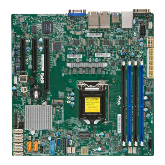
• Product safety info: http://www.supermicro.com/about/policies/safety_information.cfm • If you have any questions, please contact our support team at: support@supermicro.com This manual may be periodically updated without notice. Please check the Supermicro website for possible updates to the manual revision level. - Page 8 X11SSH-F/-LN4F User Manual Figure 1-1. X11SSH-F Motherboard Image Note: All graphics shown in this manual were based upon the latest PCB revision available at the time of publication of the manual. The motherboard you received may or may not look exactly the same as the graphics shown in this manual.
- Page 9 Chapter 1: Introduction Figure 1-2. X11SSH-LN4F Motherboard Image...
- Page 10 X11SSH-F/-LN4F User Manual Figure 1-3. X11SSH-F/-LN4F Motherboard Layout (not drawn to scale) COM 1 USB 6/7 USB 0/1 LAN 2/4 LAN 1/3 JUIDB1 (3.0) IPMI_LAN LED BMC COM2 BAR CODE JPWR2 JPL3 JPL4 JPL2 JPL1 MAC CODE JPWR1 IPMI CODE...
-
Page 11: Quick Reference
Chapter 1: Introduction Quick Reference IPMI_LAN LAN2 LAN1 JUIDB1 LAN4 COM1 LAN3 USB0/1 USB6/7 COM 1 USB 6/7 USB 0/1 LAN 2/4 LAN 1/3 JUIDB1 (3.0) JOH1 FAN4 IPMI_LAN LED BMC COM2 BAR CODE LEDBMC COM2 JPG1 JPWR2 JPWR2 JPL3 JPL4 JPL3 JBR1... -
Page 12: Quick Reference Table
X11SSH-F/-LN4F User Manual Quick Reference Table Jumper Description Default Setting LAN4 LINK ACK (-LN4F only) Off (Disabled) LAN3 LINK ACK (-LN4F only) Off (Disabled) JBR1 BIOS Recovery Pins 1-2 (Normal) JBT1 Clear CMOS See Chapter 2 C1/JI SMB to PCI Slots... - Page 13 Chapter 1: Introduction Connector Description PCI-E (PCH) Slot 4 PCI-Express 3.0 x4in x8 Slot PCI-E (CPU) Slot 5 PCI-Express 3.0 x8 Slot PCI-E (CPU) Slot 6 PCI-Express 3.0 x8in x16 Slot Internal Speaker/Buzzer USB 0/1 Back Panel USB 2.0 Ports USB 2/3, USB 4/5 Front Accessible USB 2.0 Headers USB 6/7...
-
Page 14: Motherboard Features
• 16GB, 8GB, and 4GB, up to 64GB at 1.2V Note 1: Memory speed support depends on the processors used in the system. Note 2: For the latest CPU/memory updates, please refer to our website at http://www.supermicro.com/products/ motherboard. Chipset •... - Page 15 Chapter 1: Introduction Motherboard Features Peripheral Devices • Two (2) USB 2.0 ports on the rear I/O panel (USB 0/1) • Two (2) front accessible USB 2.0 headers (USB 2/3, USB 4/5) • Two (2) USB 3.0 ports on the rear I/O panel (USB 6/7) •...
- Page 16 Note 1: The CPU maximum thermal design power (TDP) is subject to chassis and heatsink cooling restrictions. For proper thermal management, please check the chas- sis and heatsink specifications for proper CPU TDP sizing. Note 2: For IPMI configuration instructions, please refer to the Embedded IPMI Con- figuration User's Guide available at http://www.supermicro.com/support/manuals/.
-
Page 17: System Block Diagram
Chapter 1: Introduction Figure 1-4. System Block Diagram IMVP 8 3 PHASE 2 PHASE #B-2 for Vcore #B-1 #A-2 PCI-E X8 Gen3 #A-1 SLOT6 PCIe3.0 x8 (x16) #8-15 PCI-E X8 Gen3 Skt-H4 SLOT5 PCIe3.0 x8 LGA1151 #0-7 DMI3 DMI3 x4 PCI-E X1 Gen3 LAN 4 RJ45... -
Page 18: Processor And Chipset Overview
1.2 Processor and Chipset Overview Built upon the functionality and capability of the Intel E3-1200 v5 series processors (Socket LGA 1151) and the Intel C236 PCH, the X11SSH-F/-LN4F motherboard offers maximum I/O expandability, energy efficiency, and data reliability in a 14-nm process architecture, and is optimized for embedded storage solutions, networking applications, or cloud-computing platforms. -
Page 19: System Health Monitoring
Chapter 1: Introduction 1.4 System Health Monitoring This motherboard has an onboard Baseboard Management Controller (BMC) chip that supports system health monitoring. Onboard Voltage Monitors An onboard voltage monitor will scan the voltages of onboard chipset, memory, CPU, and battery continuously. Once a voltage becomes unstable, a warning is given, or an error message is sent to the screen. -
Page 20: Power Supply
As with all computer products, a stable power source is necessary for proper and reliable operation. It is even more important for processors that have high CPU clock rates. The X11SSH-F/-LN4F motherboard accommodates 24-pin ATX power supplies. Although most power supplies generally meet the specifications required by the CPU, some are inadequate. -
Page 21: Chapter 2 Installation
Chapter 2: Installation Chapter 2 Installation 2.1 Static-Sensitive Devices Electrostatic Discharge (ESD) can damage electronic com ponents. To prevent damage to your motherboard, it is important to handle it very carefully. The following measures are generally sufficient to protect your equipment from ESD. Precautions •... -
Page 22: Motherboard Installation
X11SSH-F/-LN4F User Manual 2.2 Motherboard Installation All motherboards have standard mounting holes to fit different types of chassis. Make sure that the locations of all the mounting holes for both the motherboard and the chassis match. Although a chassis may have both plastic and metal mounting fasteners, metal ones are highly recommended because they ground the motherboard to the chassis. -
Page 23: Installing The Motherboard
Chapter 2: Installation Installing the Motherboard 1. Install the I/O shield into the back of the chassis. 2. Locate the mounting holes on the motherboard. See the previous page for the location. 3. Locate the matching mounting holes on the chassis. Align the mounting holes on the motherboard against the mounting holes on the chassis. -
Page 24: Processor And Heatsink Installation
CPU socket cap is in place and none of the socket pins are bent; otherwise, contact your retailer immediately. • Refer to the Supermicro website for updates on CPU support. Installing the LGA1151 Processor 1. Press the load lever to release the load plate, which covers the CPU socket, from its locking position. - Page 25 Chapter 2: Installation 2. Gently lift the load lever to open the load plate. Remove the plastic cap. 3. Use your thumb and your index finger to hold the CPU at the North center edge and the South center edge of the CPU. North Center Edge South Center Edge 4.
- Page 26 X11SSH-F/-LN4F User Manual 5. Do not rub the CPU against the surface or against any pins of the socket to avoid damaging the CPU or the socket. 6. With the CPU inside the socket, inspect the four corners of the CPU to make sure that the CPU is properly installed.
-
Page 27: Installing An Active Cpu Heatsink With Fan
5. Apply the proper amount of thermal grease on the CPU. Note: If your heatsink came with a ther- mal pad, please ignore this step. Recommended Supermicro heatsink: 6. If necessary, rearrange the wires to SNK-P0046A4 or SNK-P0051AP4 make sure that the wires are not pinched... - Page 28 X11SSH-F/-LN4F User Manual 7. Align the four heatsink fasteners with the mounting holes on the motherboard. Gently push the pairs of diagonal fasteners (#1 & #2, and #3 & #4) into the mounting holes until you hear a click. Also, make sure to orient each fastener so that the narrow end of the groove is pointing outward.
-
Page 29: Removing The Active Heatsink
Chapter 2: Installation Removing the Active Heatsink Note: We do not recommend that the CPU or the heatsink be removed. However, if you do need to remove the heatsink, please follow the instructions below to remove the heatsink and to prevent damage done to the CPU or other components. -
Page 30: Installing A Passive Cpu Heatsink
X11SSH-F/-LN4F User Manual Installing a Passive CPU Heatsink 1. Do not apply thermal grease to the heatsink or the CPU die; the required amount has already been applied. 2. Place the heatsink on top of the CPU so that the four mounting holes are aligned with those on the motherboard and the underlying heatsink bracket. -
Page 31: Removing The Passive Heatsink
Chapter 2: Installation Removing the Passive Heatsink Note: We do not recommend that the CPU or the heatsink be removed. However, if you do need to remove the heatsink, please follow the instructions below to remove the heatsink and to prevent damage done to the CPU or other components. 1. -
Page 32: Memory Support And Installation
Memory Support The X11SSH-F/-LN4F motherboard supports up to 64GB of unbuffered (UDIMM) DDR4 ECC 2133/1866/1600/1333MHz memory in four memory slots. Populating these DIMM slots with memory modules of the same type and size will result in interleaved memory, which will improve memory performance. -
Page 33: Dimm Module Population Sequence
Chapter 2: Installation DIMM Module Population Sequence When installing memory modules, the DIMM slots should be populated in the following order: DIMMB2, DIMMA2, DIMMB1, DIMMA1. • Always use DDR4 DIMM modules of the same type, size and speed. • Mixed DIMM speeds can be installed. However, all DIMMs will run at the speed of the slowest DIMM. -
Page 34: Dimm Installation
X11SSH-F/-LN4F User Manual DIMM Installation COM 1 USB 6/7 LAN 2/4 USB 0/1 LAN 1/3 JUIDB1 (3.0) 1. Insert the desired number of DIMMs into IPMI_LAN LED BMC COM2 BAR CODE the memory slots, starting with DIMMB2 JPWR2 JPL3 JPL4... -
Page 35: Rear I/O Ports
Chapter 2: Installation 2.5 Rear I/O Ports See Figure 2-2 below for the locations and descriptions of the various I/O ports on the rear of the motherboard. COM 1 USB 6/7 USB 0/1 LAN 2/4 LAN 1/3 JUIDB1 (3.0) IPMI_LAN LED BMC COM2 BAR CODE... - Page 36 X11SSH-F/-LN4F User Manual VGA Port A video (VGA) port is located next to LAN2 on the I/O back panel. Refer to the board layout below for the location. Serial Ports Two COM connections (COM1 & COM2) are located on the motherboard. COM1 is located on the I/O back panel.
-
Page 37: Lan Ports
Chapter 2: Installation LAN Ports Two Gigabit Ethernet ports (LAN1 and LAN2) are located on the I/O back panel on the motherboard. In addition, a dedicated IPMI LAN is located above USB 0/1 ports on the back panel. All of these ports accept RJ45 cables. Please refer to the LED Indicator section for LAN LED information. - Page 38 X11SSH-F/-LN4F User Manual Universal Serial Bus (USB) Ports There are two USB 2.0 ports (USB 0/1) and two USB 3.0 ports (USB 6/7) located on the I/O back panel. The motherboard also has two front access USB 2.0 headers (USB2/3 and USB4/5) and one front access USB 3.0 header (USB8/9).
- Page 39 Chapter 2: Installation Front Panel USB 8/9 (3.0) Pin Definitions Pin# Definition Pin# Definition VBUS Power Stda_SSRX- USB3_RN Stda_SSRX+ USB3_RP Stda_SSTX- USB3_TN Stda_SSTX+ USB3_TP USB_N USB_P Type A USB 10 (3.0) Pin Definitions Pin# Definition Pin# Definition VBUS SSRX- USB_N SSRX+ USB_P Ground...
-
Page 40: Front Control Panel
JF1 contains header pins for various buttons and indicators that are normally located on a control panel at the front of the chassis. These connectors are designed specifically for use with Supermicro chassis. See the figure below for the descriptions of the front control panel buttons and LED indicators. -
Page 41: Power Button
Chapter 2: Installation Power Button The Power Button connection is located on pins 1 and 2 of JF1. Momentarily contacting both pins will power on/off the system. This button can also be configured to function as a suspend button (with a setting in the BIOS - see Chapter 4). To turn off the power when the system is in suspend mode, press the button for 4 seconds or longer. - Page 42 X11SSH-F/-LN4F User Manual Power Fail LED The Power Fail LED connection is located on pins 5 and 6 of JF1. Refer to the table below for pin definitions. Power Fail LED Pin Definitions (JF1) Pin# Definition 3.3V PWR Supply Fail...
- Page 43 Chapter 2: Installation NIC1/NIC2 (LAN1/LAN2) The NIC (Network Interface Controller) LED connection for LAN port 1 is located on pins 11 and 12 of JF1, and the LED connection for LAN port 2 is on pins 9 and 10. Attach the NIC LED cables here to display network activity.
-
Page 44: Nmi Button
X11SSH-F/-LN4F User Manual Power LED The Power LED connection is located on pins 15 and 16 of JF1. Refer to the table below for pin definitions. Power LED Pin Definitions (JF1) Pin# Definition 3.3V PWR LED NMI Button The non-maskable interrupt button header is located on pins 19 and 20 of JF1. Refer to the table below for pin definitions. -
Page 45: Connectors
Chapter 2: Installation 2.7 Connectors Power Connections Main ATX Power Supply Connector The primary power supply connector (JPWR1) meets the ATX SSI EPS 12V specification. You must also connect the 8-pin (JPWR2) processor power connector to your power supply. ATX Power 24-pin Connector Pin Definitions Pin# Definition... - Page 46 X11SSH-F/-LN4F User Manual Secondary Power Connector JPWR2 must also be connected to the power supply. This connector is used to power the processor(s). +12V 8-pin Power Pin Definitions Pin# Definition 1 - 4 Ground 5 - 8 +12V Required Connection Important: To provide adequate power supply to the motherboard, be sure to connect the 24-pin ATX PWR and the 8-pin PWR connectors to the power supply.
-
Page 47: Headers
Headers Fan Headers The X11SSH-F/-LN4F has five fan headers (Fan1-Fan4, FanA). All these 4-pin fans headers are backward-compatible with the traditional 3-pin fans. However, fan speed control is available for 4-pin fans only by Thermal Management via the IPMI 2.0 interface. Refer to the table below for pin definitions. - Page 48 X11SSH-F/-LN4F User Manual Power LED/Speaker Pins 1-3 of JD1 are used for power LED indication, and pins 4-7 are for the speaker. Please note that the speaker connector pins (4-7) are used with an external speaker. If you wish to use the onboard speaker, you should close pins 6-7 with a cap.
- Page 49 Chapter 2: Installation SGPIO Headers Two I-SGPIO (Serial Link General Purpose Input/Output) headers are located on the motherboard. They support the onboard I-SATA 3.0 ports. Refer to the tables below for pin definitions. SGPIO Header I-SGPIO 1/2 Pin Definitions I-SGPIO1 Ports 2-4 Pin# Definition...
- Page 50 X11SSH-F/-LN4F User Manual TPM/Port 80 Header A Trusted Platform Module (TPM)/Port 80 header is located at JTPM1 to provide TPM support and Port 80 connection. Use this header to enhance system performance and data security. Refer to the table below for pin definitions.
- Page 51 Chapter 2: Installation Standby Power The Wake-On-LAN (WOL) header is located at JSTBY1 on the motherboard. Refer to the table below for pin definitions. Wake-On-LAN Pin Definitions Pin# Definition +5V Standby Ground Wake-up Internal Speaker/Buzzer The Internal Speaker (SP1) can be used to provide audible notifications using various beep codes.
- Page 52 X11SSH-F/-LN4F User Manual Power SMB (I C) Header The Power System Management Bus (I C) connector (JPI C1) monitors the power supply, fan, and system temperatures. Refer to the table below for pin definitions. Power SMB Header Pin Definitions Pin#...
-
Page 53: Chassis Intrusion
Chapter 2: Installation Overheat/Fan Fail LED Header The JOH1 header is used to connect an LED indicator to provide warnings of chassis overheating and fan failure. This LED will blink when a fan failure occurs. Refer to the tables below for pin definitions. Overheat LED Header Overheat LED Status... - Page 54 X11SSH-F/-LN4F User Manual SATA Ports Eight SATA 3.0 connectors are located on the X11SSH-F/-LN4F motherboard, supported by the Intel C236 PCH chip. These SATA ports support RAID 0, 1, 5, and 10. SATA ports provide serial-link signal connections, which are faster than the connections of Parallel ATA. Refer to the tables below for pin definitions.
- Page 55 Chapter 2: Installation M.2 Slot The X11SSH-F/-LN4F motherboard contains one M.2 socket at J23. M.2 was formerly Next Generation Form Factor (NGFF) and serves to replace mini PCI-E and mSATA. M.2 allows for a greater variety of card sizes, increased functionality, and spatial efficiency. The M.2 socket on the X11SSH-F/-LN4F motherboard supports PCI-E 3.0 x2 M.2 cards in the 22x80mm...
- Page 56 X11SSH-F/-LN4F User Manual Unit Identifier Switch/UID LED Indicator A rear Unit Identifier (UID) switch and a rear UID LED (LED1) are located next to the VGA port on the motherboard. The front UID switch and the front UID LED are both located on the Front Panel Control (JF1) (with the front UID switch on pin 13, and the front LED on pin 7 of JF1).
-
Page 57: Jumper Settings
Chapter 2: Installation 2.8 Jumper Settings How Jumpers Work To modify the operation of the motherboard, jumpers can be used to choose between optional settings. Jumpers create shorts between two pins to change the function of the connector. Pin 1 is identified with a square solder pad on the printed circuit board. See the diagram below for an example of jumping pins 1 and 2. - Page 58 X11SSH-F/-LN4F User Manual CMOS Clear JBT1 is used to clear the CMOS. Instead of pins, this "jumper" consists of contact pads to prevent accidental clearing of the CMOS. To clear the CMOS, use a metal object such as a small screwdriver to touch both pads at the same time to short the connection.
- Page 59 Chapter 2: Installation LAN Port Enable/Disable Change the setting of jumper JPL1/JPL2 to enable or disable the LAN1/LAN2 LAN ports, respectively. The default setting is Enabled. Note: X11SSH-LN4F has additional jumpers JPL3/JPL4 which enable or disable LAN ports 3/4 on the motherboard. LAN1-LAN4 Enable/Disable Jumper Settings Jumper Setting...
- Page 60 X11SSH-F/-LN4F User Manual BIOS Recovery Use jumper JBR1 to recover the BIOS settings on the motherboard. Refer to the table below for jumper settings. The default setting is Normal. BIOS Recovery Jumper Settings Jumper Setting Definition Pins 1-2 Normal Pins 2-3...
- Page 61 Chapter 2: Installation BMC Enabled Jumper JPB1 allows you to enable the embedded ASpeed AST2400 Baseboard Management Controller (BMC) to provide IPMI 2.0/KVM support on the motherboard. Refer to the table below for jumper settings. The default setting is BMC Enable. BMC Enable Jumper Settings Jumper Setting...
-
Page 62: Led Indicators
X11SSH-F/-LN4F User Manual 2.9 LED Indicators LAN LEDs Two LAN ports (LAN 1 and LAN 2) are located on the I/O back panel of the motherboard. Each Ethernet LAN port has two LEDs. The yellow LED indicates activity, while the other Link LED may be green, amber, or off to indicate the speed of the connection. - Page 63 Chapter 2: Installation Dedicated IPMI LAN LEDs In addition to LAN 1 and LAN 2, an IPMI LAN is also located on the I/O back panel. The amber LED on the right indicates activity, while the green LED on the left indicates the speed LAN 1/LAN 2 of the connection.
- Page 64 X11SSH-F/-LN4F User Manual BMC Heartbeat LED A BMC Heartbeat LED is located at LEDBMC on the motherboard. When LEDBMC is blinking, the BMC is functioning normally. Refer to the table below for more information. Onboard Power LED Indicator LED Color...
- Page 65 Chapter 2: Installation M.2 LED An M.2 LED is located at LE3 on the motherboard. When LE3 is blinking, M.2 functions normally. Refer to the table below for more information. M.2 LED State LED Color Definition Green: Device Working Blinking COM 1 1.
-
Page 66: Chapter 3 Troubleshooting
X11SSH-F/-LN4F User Manual Chapter 3 Troubleshooting 3.1 Troubleshooting Procedures Use the following procedures to troubleshoot your system. If you have followed all of the procedures below and still need assistance, refer to the ‘Technical Support Procedures’ and/ or ‘Returning Merchandise for Service’ section(s) in this chapter. Always disconnect the AC power cord before adding, changing or installing any non hot-swap hardware components. -
Page 67: System Boot Failure
1. Make sure that the memory modules are compatible with the system and that the DIMMs are properly and fully installed. (For memory compatibility, refer to the memory compatibility chart posted on our website at http://www.supermicro.com.) 2. Check if different speeds of DIMMs have been installed. It is strongly recommended that you use the same RAM type and speed for all DIMMs in the system. -
Page 68: When The System Becomes Unstable
X11SSH-F/-LN4F User Manual 5. Make sure that all memory modules are fully seated in their slots. Follow the instructions given in Section 2-5 in Chapter 2. 6. Please follow the instructions given in the DIMM population tables listed in Section 2-5 to install your memory modules. - Page 69 Chapter 3: Troubleshooting 6. Proper software support: Make sure that the correct drivers are used. B. If the system becomes unstable before or during OS installation, check the following: 1. Source of installation: Make sure that the devices used for installation are working properly, including boot devices such as CD/DVD and CD/DVD-ROM.
-
Page 70: Technical Support Procedures
BIOS release date/version (This can be seen on the initial display when your system first boots up.) • System configuration 4. An example of a Technical Support form is on our website at http://www.supermicro.com/ RmaForm/. • Distributors: For immediate assistance, please have your account number ready when placing a call to our Technical Support department. -
Page 71: Frequently Asked Questions
Updated BIOS files are located on our website at http://www. supermicro.com. Please check our BIOS warning message and the information on how to update your BIOS on our website. Select your motherboard model and download the BIOS file to your computer. -
Page 72: Battery Removal And Installation
X11SSH-F/-LN4F User Manual 3.4 Battery Removal and Installation Battery Removal To remove the onboard battery, follow the steps below: 1. Power off your system and unplug your power cable. 2. Locate the onboard battery as shown below. 3. Using a tool such as a pen or a small screwdriver, push the battery lock outwards to unlock it. -
Page 73: Returning Merchandise For Service
Shipping and handling charges will be applied for all orders that must be mailed when service is complete. For faster service, you can also request a RMA authorization online (http://www.supermicro. com/RmaForm/). -
Page 74: Chapter 4 Bios
Chapter 4 BIOS 4.1 Introduction This chapter describes the AMIBIOS™ setup utility for the X11SSH-F/X11SSH-LN4F motherboard. The BIOS is stored on a Flash EEPROM and can be easily upgraded using a flash program. Note: Due to periodic changes to the BIOS, some settings may have been added or deleted and might not yet be recorded in this manual. -
Page 75: Main Setup
Note: For AMI UEFI BIOS Recovery, please refer to the UEFI BIOS Recovery User Guide posted @ http://www.supermicro.com/support/manuals/. 4.2 Main Setup When you first enter the AMI BIOS setup utility, you will enter the Main setup screen. You can always return to the Main setup screen by selecting the Main tab on the top of the screen. - Page 76 X11SSH-F/-LN4F User Manual System Date/System Time Use this option to change the system date and time. Highlight System Date or System Time using the arrow keys. Enter new values using the keyboard. Press the <Tab> key or the arrow keys to move between fields. The date must be entered in Day MM/DD/YYYY format. The time is entered in HH:MM:SS format.
-
Page 77: Advanced Setup Configurations
Chapter 4: BIOS 4.3 Advanced Setup Configurations Use the arrow keys to select Boot Setup and press <Enter> to access the submenu items. Warning: Take caution when changing the Advanced settings. An incorrect value, an inaccurate DRAM frequency, or a wrong DRAM timing setting may make the system unstable. When this occurs, revert the setting to the manufacture default settings. -
Page 78: Power Configuration
X11SSH-F/-LN4F User Manual immediately and allow the drives that are attached to these host adaptors to function as bootable disks. If this item is set to Postponed, the ROM BIOS of the host adaptors will not capture Interrupt 19 immediately and allow the drives attached to these adaptors to function as bootable devices at bootup. - Page 79 Chapter 4: BIOS • CPU Speed • Processor Cores • Hyper Threading Technology • Intel VT-x Technology • Intel SMX Technology • 64-bit • EIST Technology • CPU C3 State • CPU C6 State • CPU C7 State • L1 Data Cache •...
- Page 80 X11SSH-F/-LN4F User Manual the user with greater reliability, security and availability in networking and data-sharing. The settings are Enabled and Disabled. Hardware Prefetcher (Available when supported by the CPU) If set to Enabled, the hardware prefetcher will prefetch streams of data and instructions from the main memory to the L2 cache to improve CPU performance.
- Page 81 Chapter 4: BIOS Power Limit 2 Override Select Enabled to support rapid power limit (PL2) override. The default setting is Enabled. Power Limit 2 Use this item to configure the value for Power Limit 2. The value is in milli watts and the step size is 125mW.
-
Page 82: Chipset Configuration
X11SSH-F/-LN4F User Manual Package C-State Demotion Use this feature to enable or disable the Package C-State demotion. The options are Disabled and Enabled. Package C-State Un-Demotion Use this feature to enable or disable the Package C-State un-demotion. The options are Disabled and Enabled. -
Page 83: Graphics Configuration
Chapter 4: BIOS VT-d Select Enabled to enable Intel Virtualization Technology support for Direct I/O VT-d by reporting the I/O device assignments to VMM through the DMAR ACPI Tables. This feature offers fully-protected I/O resource-sharing across the Intel platforms, providing the user with greater reliability, security and availability in networking and data-sharing. - Page 84 X11SSH-F/-LN4F User Manual DMI VC1 Control Use this feature to enable or disable DMI Virtual Channel 1. The options are Enabled and Disabled. DMI VCm Control Use this feature to enable or disable the DMI Virtual Channel map. The options are Enabled and Disabled.
-
Page 85: Memory Configuration
Chapter 4: BIOS Program PCIe ASPM After OPROM PCIe ASPM, the Active State Power Management for PCI-Express slots, is a power management protocol used to manage power consumption of serial-link devices installed on PCI-Exp slots during a prolonged off-peak time. If this item is set to Enabled, PCI-E ASMP will be programmed after OPROM. -
Page 86: Pci Express Configuration
X11SSH-F/-LN4F User Manual Fast Boot Use this feature to enable or disable fast path through the memory reference code. The options are Enabled and Disabled. REFRESH_2X_MODE Use this feature to select the refresh mode. The options are Disabled, 1-Enabled for WARM or HOT, and 2-Enabled HOT only. -
Page 87: Sata Configuration
Chapter 4: BIOS PCH SLOT4 PCI-E 3.0 X4 (IN X8) SLOT4 ASPM Use this item to set the Active State Power Management (ASPM) level for the PCI-E device installed on the slot specified. Select Auto for the system BIOS to automatically set the ASPM level based on the system configuration. - Page 88 X11SSH-F/-LN4F User Manual SATA Mode Selection Use this item to select the mode for the installed SATA drives. The options are AHCI and RAID. SATA Frozen Use this item to enable the HDD Security Frozen Mode. The options are Enabled and Disabled.
- Page 89 Chapter 4: BIOS SATA Port 0~ Port 7 This item displays the information detected on the installed SATA drive on the particular SATA port. Port 0~ Port 7 The status of a SATA port will be displayed as detected by the BIOS. Port 0 ~ Port 7 Software Preserve The status of software preserve of a SATA port will display as it is detected by the BIOS.
- Page 90 X11SSH-F/-LN4F User Manual PCH SLOT4 PCI-E 3.0 X4 (IN X8) OPROM Use this feature to select which firmware type to be loaded for the add-on card in this slot for system boot. The options are Disabled, Legacy, and EFI. PCH SLOT5 PCI-E 3.0 X8 OPROM Use this feature to select which firmware type to be loaded for the add-on card in this slot for system boot.
-
Page 91: Super Io Configuration
Chapter 4: BIOS PXE boot wait time Use this option to specify the wait time to press the ESC key to abort the PXE boot. Press "+" or "-" on your keyboard to change the value. The default setting is 0. Media detect count Use this option to specify the number of times media will be checked. -
Page 92: Intel Server Platform Services
X11SSH-F/-LN4F User Manual Logical Device Settings This item displays the current status of a serial part specified by the user. Serial Port 2 Change Settings This feature specifies the base I/O port address and the Interrupt Request address of a serial port specified by the user. -
Page 93: Serial Port Console Redirection
Chapter 4: BIOS Serial Port Console Redirection COM1 Console Redirection Console Redirection Select Enabled to enable console redirection support for a serial port specified by the user. The options are Enabled and Disabled. If this feature is set to Enabled, the following items will become available: COM1 Console Redirection Settings This feature allows the user to specify how the host computer will exchange data with the... - Page 94 X11SSH-F/-LN4F User Manual COM1 Flow Control Use this feature to set the flow control for Console Redirection to prevent data loss caused by buffer overflow. Send a "Stop" signal to stop sending data when the receiving buffer is full. Send a "Start" signal to start sending data when the receiving buffer is empty. The options are None and Hardware RTS/CTS.
- Page 95 Chapter 4: BIOS SOL/COM2 Console Redirection Settings Use this feature to specify how the host computer will exchange data with the client computer, which is the remote computer used by the user. COM2 Terminal Type Use this feature to select the target terminal emulation type for Console Redirection. Select VT100 to use the ASCII Character set.
- Page 96 X11SSH-F/-LN4F User Manual COM2 Recorder Mode Select Enabled to capture the data displayed on a terminal and send it as text messages to a remote server. The options are Disabled and Enabled. COM2 Resolution 100x31 Select Enabled for extended-terminal resolution support. The options are Disabled and Enabled.
-
Page 97: Acpi Settings
Chapter 4: BIOS transmission speed may be required for long and busy lines. The options are 9600, 19200, 57600, and 115200 (bits per second). Flow Control Use this item to set the flow control for Console Redirection to prevent data loss caused by buffer overflow. -
Page 98: Iscsi Configuration
X11SSH-F/-LN4F User Manual Trusted Computing Configuration (Available when a TPM device is installed and the onboard TPM jumper is enabled) Security Device Support If this feature and the TPM jumper on the motherboard are both set to Enabled, onbaord security devices will be enabled for TPM (Trusted Platform Module) support to enhance data integrity and network security. -
Page 99: Event Logs
Chapter 4: BIOS Add an Attempt Delete Attempts Change Attempt order 4.4 Event Logs This submenu allows the user to configure Event Log settings. Change SMBIOS Event Log Settings This feature allows the user to configure SMBIOS Event settings. Enabling/Disabling Options SMBIOS Event Log Select Enabled to enable SMBIOS (System Management BIOS) Event Logging during system... -
Page 100: Ipmi
X11SSH-F/-LN4F User Manual When Log is Full Select Erase Immediately to immediately erase all errors in the SMBIOS event log when the event log is full. Select Do Nothing for the system to do nothing when the SMBIOS event log is full. -
Page 101: System Event Log
Chapter 4: BIOS The following IPMI information will be displayed: • IPMI Firmware Revision • IPMI Status System Event Log Enabling/Disabling Options SEL Components Select Enabled to enable all system event logging support at bootup. The options are Enabled and Disabled. - Page 102 X11SSH-F/-LN4F User Manual Configuration Address Source (Available when the item above - Update IPMI LAN Configuration is set to Yes) Use this item to select the IP address source for this computer. If Static is selected, you will need to know the IP address of this computer and enter it to the system manually in the field.
-
Page 103: Security
Chapter 4: BIOS 4.6 Security This menu allows the user to configure the following security settings for the system. Password Check Select Setup for the system to check for a password at Setup. Select Always for the system to check for a password at bootup or upon entering the BIOS Setup utility. The options are Setup and Always. -
Page 104: Key Management
X11SSH-F/-LN4F User Manual Key Management This submenu allows the user to configure the following Key Management settings. Provision Factory Default Keys (Available when the system is in Setup Mode) Select Enabled to install factory default secure-boot keys. The options are Enabled and Disabled. -
Page 105: Boot Settings
Chapter 4: BIOS 4.7 Boot Settings This submenu allows the user to configure Boot settings for this system: Boot Configuration Boot Mode Select Use this item to select the type of device to be used for system boot. The options are Legacy, UEFI, and Dual. - Page 106 X11SSH-F/-LN4F User Manual Delete Boot Option Use this item to select a boot device to delete from the boot priority list. Delete Boot Option Select the target boot device to delete from the boot priority list. Hard Disk Drive BBS Priorities •...
-
Page 107: Save & Exit
Chapter 4: BIOS 4.8 Save & Exit Select the Exit tab from the BIOS setup utility screen to enter the Exit BIOS Setup screen. Discard Changes and Exit Select this option to quit the BIOS Setup without making any permanent changes to the system configuration, and reboot the computer. - Page 108 X11SSH-F/-LN4F User Manual Save As User Defaults To set this feature, select Save as User Defaults from the Exit menu and press <Enter>. This enables the user to save any changes to the BIOS setup for future use. Restore User Defaults To set this feature, select Restore User Defaults from the Exit menu and press <Enter>.
-
Page 109: Appendix A Bios Codes
Appendix A: BIOS Codes Appendix A BIOS Codes BIOS Error POST (Beep) Codes During the POST (Power-On Self-Test) routines, which are performed upon each system boot, errors may occur. Non-fatal errors are those which, in most cases, allow the system to continue to boot. These error messages normally appear on the screen. -
Page 110: Appendix B Software Installation
Software Installation B.1 Installing Software Programs The Supermicro FTP site contains drivers and utilities for your system at ftp://ftp.supermicro. com. Some of these must be installed, such as the chipset driver. After accessing the FTP site, go into the CDR_Images directory and locate the ISO file for your motherboard. -
Page 111: Superdoctor ® 5
B.2 SuperDoctor ® The Supermicro SuperDoctor 5 is a hardware monitoring program that functions in a command-line or web-based interface in Windows and Linux operating systems. The program monitors system health information, such as CPU temperature, system voltages, system power consumption, and fan speed, and provides alerts via email or the Simple Network Management Protocol (SNMP). - Page 112 X11SSH-F/-LN4F User Manual Note: The SuperDoctor 5 program and user’s manual can be downloaded from the Supermicro website at http://www.supermicro.com/products/nfo/sms_sd5.cfm.
-
Page 113: Appendix C Standardized Warning Statements
The following statements are industry standard warnings, provided to warn the user of situations which have the potential for bodily injury. Should you have questions or experience difficulty, contact Supermicro's Technical Support department for assistance. Only certified technicians should attempt to install or configure components. - Page 114 X11SSH-F/-LN4F User Manual Attention Danger d'explosion si la pile n'est pas remplacée correctement. Ne la remplacer que par une pile de type semblable ou équivalent, recommandée par le fabricant. Jeter les piles usagées conformément aux instructions du fabricant. ¡Advertencia! Existe peligro de explosión si la batería se reemplaza de manera incorrecta. Reemplazar la batería exclusivamente con el mismo tipo o el equivalente recomendado por el fabricante.
-
Page 115: Product Disposal
Appendix C: Warning Statements Product Disposal Warning! Ultimate disposal of this product should be handled according to all national laws and regulations. 製品の廃棄 この製品を廃棄処分する場合、 国の関係する全ての法律 ・ 条例に従い処理する必要があります。 警告 本产品的废弃处理应根据所有国家的法律和规章进行。 警告 本產品的廢棄處理應根據所有國家的法律和規章進行。 Warnung Die Entsorgung dieses Produkts sollte gemäß allen Bestimmungen und Gesetzen des Landes erfolgen. -
Page 116: Appendix D Uefi Bios Recovery
Warning: Do not upgrade the BIOS unless your system has a BIOS-related issue. Flashing the wrong BIOS can cause irreparable damage to the system. In no event shall Supermicro be liable for direct, indirect, special, incidental, or consequential damages arising from a BIOS update. - Page 117 Directory of a USB device or a writeable CD/DVD. Note: If you cannot locate the "Super.ROM" file in your driver disk, visit our website at www.supermicro.com to download the BIOS image into a USB flash device and rename it "Super.ROM" for BIOS recovery use.
- Page 118 X11SSH-F/-LN4F User Manual 4. After locating the new BIOS binary image, the system will enter the BIOS Recovery menu as shown below. Note: At this point, you may decide if you want to start the BIOS recovery. If you decide to proceed with BIOS recovery, follow the procedures below.
- Page 119 6. After the BIOS recovery process has completed, press any key to reboot the system. 7. Using a different system, extract the BIOS package into a bootable USB flash drive. 8. When a DOS prompt appears, enter FLASH.BAT BIOSname.### at the prompt. Note: Do not interrupt this process until the BIOS flashing is complete.
-
Page 120: Appendix E Dual Boot Block
X11SSH-F/-LN4F User Manual Appendix E Dual Boot Block E.1 Introduction This motherboard supports the Dual Boot Block feature, which is the last-ditch mechanism to recover the BIOS boot block. This section provides an introduction to the feature. BIOS Boot Block A BIOS boot block is the minimum BIOS loader required to enable necessary hardware components for the BIOS crisis recovery flash that will update the main BIOS block. - Page 121 Appendix E: Dual Boot Block E.2 Steps to Reboot the System by Using Jumper JBR1 1. Power down the system. 2. Close pins 2-3 on jumper JBR1, and power on the system. 3. Follow the BIOS recovery SOP listed in the previous chapter (Appendix D). 4.
Need help?
Do you have a question about the X11SSH-F and is the answer not in the manual?
Questions and answers