
Related Manuals for Supermicro X11SSN Series


Summary of Contents for Supermicro X11SSN Series
- Page 1 X11SSN-H/-E/-L X11SSN-H/-E/-L-WOHS X11SSN-H/-E/-L-VDC X11SSN-H/-E/-L-001 USER’S MANUAL Revision 1.1...
- Page 2 State of California, USA. The State of California, County of Santa Clara shall be the exclusive venue for the resolution of any such disputes. Supermicro's total liability for all claims will not exceed the price paid for the hardware product.
- Page 3 About This Manual This manual is written for system integrators, IT technicians and knowledgeable end users. It provides information for the installation and use of the X11SSN series motherboard. About This Motherboard The X11SSN is a 3.5” Single Board Computer (size: 146mm x 102mm) that is powered by the 7th generation of Intel®...
- Page 4 Preface Manual Organization Chapter 1 describes the features, specifications and performance of the motherboard, and provides detailed information on the processor. Chapter 2 provides hardware installation instructions. Read this chapter when installing the processor, memory modules, and other hardware components into the system. If you encounter any problems, see Chapter 3, which describes troubleshooting procedures for video, memory, and system setup stored in the CMOS.
- Page 5 Super X11SSN-H/-E/-L User's Manual Contacting Supermicro Headquarters Address: Super Micro Computer, Inc. 980 Rock Ave. San Jose, CA 95131 U.S.A. Tel: +1 (408) 503-8000 Fax: +1 (408) 503-8008 Email: marketing@supermicro.com (General Information) support@supermicro.com (Technical Support) Website: www.supermicro.com Europe Address: Super Micro Computer B.V.
-
Page 6: Table Of Contents
Preface Table of Contents Chapter 1 Introduction 1.1 Checklist ..........................8 Quick Reference .......................15 Quick Reference Table ......................16 Motherboard Features .......................17 1.2 Processor Overview ......................20 1.3 Special Features ........................20 Recovery from AC Power Loss ..................21 1.4 ACPI Features ........................21 1.5 Power Supply ........................21 1.6 Super I/O ..........................22 Chapter 2 Installation 2.1 Static-Sensitive Devices .....................23... - Page 7 Super X11SSN-H/-E/-L User's Manual Chapter 3 Troubleshooting 3.1 Troubleshooting Procedures ....................50 Before Power On ......................50 No Power ..........................50 No Video ...........................51 System Boot Failure ......................51 Memory Errors ........................51 Losing the System's Setup Configuration .................52 When the System Becomes Unstable ................52 3.2 Technical Support Procedures ...................54 3.3 Frequently Asked Questions ....................55 3.4 Battery Removal and Installation ..................56...
-
Page 8: Checklist
Chapter 1 Introduction Congratulations on purchasing your computer motherboard from an industry leader. Supermicro boards are designed to provide you with the highest standards in quality and performance. In additon to the motherboard, several important parts that are included with the system are listed below. - Page 9 • If you have any questions, please contact our support team at: support@supermicro.com This manual may be periodically updated without notice. Please check the Supermicro website for possible updates to the manual revision level.
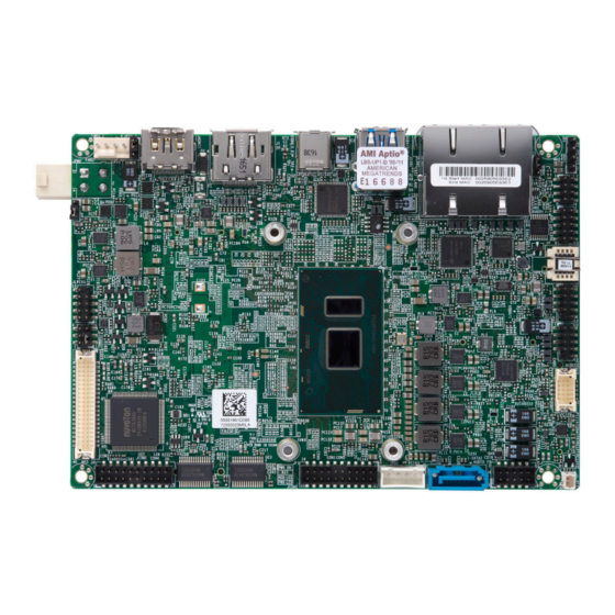
- Page 10 Super X11SSN-H/-E/-L User's Manual Figure 1-1. X11SSN Series Motherboard Image Note: All graphics shown in this manual were based upon the latest PCB revision available at the time of publication of the manual. The motherboard you received may or may not look exactly the same as the graphics shown in this manual.
- Page 11 Chapter 1: Introduction Figure 1-2. X11SSN Series Motherboard Mechanical Drawings Motherboard Top Side Motherboard Bottom Side...
- Page 12 Super X11SSN-H/-E/-L User's Manual Figure 1-3. X11SSN Series Back Panel I/O Mechanical Drawings Back Panel I/O with Heatsink (X11SSN-H/E) Back Panel I/O with Heatsink (X11SSN-H/E-VDC) Back Panel I/O with Heatsink (X11SSN-L) Continued on the next page...
- Page 13 Chapter 1: Introduction X11SSN-H/-E/-L Back Panel I/O Mechanical Drawings Back Panel I/O with Heatsink (X11SSN-L-VDC) Back Panel I/O without Heatsink (X11SSN-H/E/L-WOHS, X11SSN-H/E/L-001)
- Page 14 Super X11SSN-H/-E/-L User's Manual Figure 1-4. Motherboard Layout (not drawn to scale) Top Layout FAN1 USB6(3.0) JHDMI1 USB4/5(3.0) JPW2 JPF1 LAN2 LAN1 JGP1 SRW1 SRW2 PWR ON JLCDPWR1 SRW3 SRW4 JCOM2: COM3 COM4 AUDIO FP JPH1 I-SATA1 JCOM1: COM1 COM2 Bottom Layout DESIGNED IN USA JPW1...
-
Page 15: Quick Reference
Chapter 1: Introduction Quick Reference Top Layout SRW1 FAN1 USB4/5 (3.0) LAN2 LAN1 JPT1 DP++ USB6 (3.1) JHDMI1 SRW2 JPME2 FAN1 JPW2 USB6(3.0) JHDMI1 USB4/5(3.0) JPW2 JPF1 JPF1 JGP1 LAN2 LAN1 JGP1 SRW1 SRW2 PWR ON USB0/1 JLCDPWR1 JLCDPWR1 USB2/3 USB7 LVDS1 SRW3... -
Page 16: Quick Reference Table
Super X11SSN-H/-E/-L User's Manual Quick Reference Table Jumper Description Jumper Setting (Default *) Pin 1-3* (3.3V) JLCDPWR1 LVDS Panel VCC power source selection Pin 3-5 (5V) Pin 3-4 (12V) Pin 1-2* (FORCE POWER ON) JPF1 FORCE POWER ON Pin 2-3 (POWER BUTTON ON) Pin 1-2* (Normal) JPME2 Manufacturing Mode... -
Page 17: Motherboard Features
One Full Size Mini-PCI Express slot with mSATA (one PCIe x1 Gen3, one USB 2.0, one SATA 3.0) • One M.2 B-Key 3042/2242/2280 (PCIe x2 Gen3, one USB 2.0, one SATA 3.0) The 2242/3042 module is supported by a copper standoff for M.2 and mounting holes (Supermicro P/N: MCP-110- 00098-0N) Network •... - Page 18 Super X11SSN-H/-E/-L User's Manual Motherboard Features Peripheral Devices • Two USB 3.0 ports on the rear I/O panel (USB4/5 are Type A) • Four USB 2.0 headers (USB0/1 and USB2/3 are pin headers) • One USB 3.1 port (USB6) • One USB 3.0 OTG header (USB7 is a pin header) BIOS •...
- Page 19 NCT6106D COM 3 / 4 (RS232) I/O Panel Layout USB 3.0 USB 3.0 USB 3.1 LAN1 LAN2 TYPE C HDMI X11SSN Series Spec Chart Figure 1-6. X11SSN Series Specification Chart Base Freq Turbo Freq Power Model GbE USB3.1 HDMI2.0 Audio vPro Temp.
-
Page 20: Processor Overview
Intel vPro™ Technology and Intel Active Management Technology (Intel AMT). (For X11SSN-H/E, -VDC, -WOHS) 1.3 Special Features This section describes the health monitoring features of the X11SSN series motherboard. The motherboard has an onboard System Hardware Monitor chip that supports system health monitoring. -
Page 21: Recovery From Ac Power Loss
Chapter 1: Introduction Recovery from AC Power Loss The Basic I/O System (BIOS) provides a setting that determines how the system will respond when AC power is lost and then restored to the system. You can choose for the system to remain powered off (in which case you must press the power switch to turn it back on), or for it to automatically return to the power-on state. -
Page 22: Super I/O
Super X11SSN-H/-E/-L User's Manual 1.6 Super I/O The Super I/O (NCT6106D chip) provides four high-speed, 16550 compatible serial communication ports (UARTs), one of which supports serial infrared communication. Each UART includes a 128 byte send/receive FIFO, a programmable baud rate generator, complete modem control capability, and a processor interrupt system. -
Page 23: Chapter 2 Installation
Chapter 2: Installation Chapter 2 Installation 2.1 Static-Sensitive Devices Electrostatic Discharge (ESD) can damage electronic com ponents. To prevent damage to your motherboard, it is important to handle it very carefully. The following measures are generally sufficient to protect your equipment from ESD. Precautions •... -
Page 24: Motherboard Installation
Super X11SSN-H/-E/-L User's Manual 2.2 Motherboard Installation All motherboards have standard mounting holes to fit different types of chassis. Make sure that the locations of all the mounting holes for both the motherboard and the chassis match. Although a chassis may have both plastic and metal mounting fasteners, metal ones are highly recommended because they ground the motherboard to the chassis. -
Page 25: Installing The Motherboard
Chapter 2: Installation Installing the Motherboard 1. Locate the mounting holes on the motherboard. See the previous page for the location. 2. Locate the matching mounting holes on the chassis. Align the mounting holes on the motherboard against the mounting holes on the chassis. 3. -
Page 26: Memory Support And Installation
Super X11SSN-H/-E/-L User's Manual 2.3 Memory Support and Installation Note: Check the Supermicro website for recommended memory modules. Important: Exercise extreme care when installing or removing DIMM modules to pre- vent any possible damage. Memory Support The X11SSN-H/-E/-L supports up to 32GB of DDR4 2133MHz SO-DIMM in two memory slots on the bottom side of the motherboard. -
Page 27: So-Dimm Installation
Chapter 2: Installation SO-DIMM Installation 1. Position the SO-DIMM module's bottom key so it aligns with the receptive point on the slot. Align 2. Insert the SO-DIMM module vertically at about a 45 degree angle. Press down until the module locks into place. Insert this end first Press down until the module locks into place. -
Page 28: Rear I/O Ports
Super X11SSN-H/-E/-L User's Manual 2.4 Rear I/O Ports See Figure 2-1 below for the locations and descriptions of the various I/O ports on the rear of the motherboard. FAN1 USB6(3.0) JHDMI1 USB4/5(3.0) JPW2 JPF1 LAN2 LAN1 JGP1 SRW1 SRW2 PWR ON JLCDPWR1 SRW3 SRW4... - Page 29 Chapter 2: Installation DP++ DisplayPort, developed by the VESA consortium, delivers digital display and fast refresh rate. It can connect to virtually any display device using a DisplayPort adapter for devices such as VGA, DVI or HDMI. HDMI Port The High-Definition Multimedia Interface (HDMI) port is used to display both high definition video and digital sound through an HDMI-capable display, using the same cable.
- Page 30 Super X11SSN-H/-E/-L User's Manual LAN Ports Two LAN ports (LAN1/LAN2) are located on the I/O back panel. These ports accept RJ45 type cables. Please refer to the LED Indicator section for LAN LED information. Refer to the table below for pin defintions. LAN Port Pin Definition Pin#...
- Page 31 Chapter 2: Installation Universal Serial Bus (USB) Ports There are two USB 3.0 ports (USB4/5) and one USB 3.1 Type C port (USB6) on the I/O back panel. The motherboard also has four front access USB 2.0 headers (USB0/1 and USB2/3) and one USB 3.0 OTG header (including USB2.0 and 3.0).
-
Page 32: Front Control Panel
JF1 contains header pins for various buttons and indicators that are normally located on a control panel at the front of the chassis. These connectors are designed specifically for use with Supermicro chassis. Refer to the figure below for the descriptions of the front control panel buttons and LED indicators. - Page 33 Chapter 2: Installation Power Button The Power Button connection is located on pins 1 and 2 of JF1. Momentarily contacting both pins will power on/off the system. This button can also be configured to function as a suspend button (with a setting in the BIOS - see Chapter 4). To turn off the power in the suspend mode, press the button for at least 4 seconds.
- Page 34 Super X11SSN-H/-E/-L User's Manual HDD LED The HDD LED connection is located on pins 5 and 6 of JF1. Attach a cable here to indicate the status of HDD-related activities, including SATA activities. Refer to the table below for pin definitions. HDD LED Pin Definitions (JF1) Pin#...
-
Page 35: Connectors
Chapter 2: Installation 2.6 Connectors Power Connections SATA Power Connector The 4-pin SATA power connector JPH1 provides power to onboard HDD devices. Refer to the table below for pin definitions. 4-pin HDD Power Pin Definitions Pin# Definition Ground 12V Vertical Type Power Connector JPW2 is the 12V DC power source for the X11SSN-H/E/L-VDC motherboard. - Page 36 Super X11SSN-H/-E/-L User's Manual 4-pin 12V R/A Type Power Connector The R/A type power connector is located at JPW1 on the bottom side of the X11SSN-H/E/L, X11SSN-H/E/L-WOHS, and X11SSN-H/E/L-001 motherboard. Refer to the table below for pin definitions. +12V R/A Type Power Pin Definitions Pin# Definition...
-
Page 37: Headers
Chapter 2: Installation Headers Fan Header There is one fan header with 4-pins on the motherboard. Pins 1-3 are backward compatible with traditional 3-pin fans. The onboard fan speeds are controlled by Thermal Management (via Hardware Monitoring) in the BIOS. When using Thermal Management setting, please use all 3-pin fans or all 4-pin fans. - Page 38 Super X11SSN-H/-E/-L User's Manual Front Panel Audio Header A 10-pin front panel audio header located on the motherboard allows you to use the onboard sound for audio playback. Connect an audio cable to the this header to use this feature. Refer to the table below for pin definitions.
- Page 39 Chapter 2: Installation COM Ports There are four COM ports (JCOM1: COM1/COM2 supports two RS232/RS422/RS485 and JCOM2: COM3/COM4 supports two RS232) on the motherboard. Refer to the table below for pin definitions. Serial COM Ports (JCOM2) Serial COM Ports (JCOM1) Pin Definitions Pin Definitions Pin#...
- Page 40 Super X11SSN-H/-E/-L User's Manual LVDS Connector LVDS1 is the LVDS connector. LVDS (low-voltage differential signaling) is a high-speed digital interface that operates at low power. It is a type of connection that is used with a LVDS LCD panel. The connector combines LCD VCC Power (pins 9-10), LVDS high speed digital interface, backlight power 3.3V (pin 7) and 12V (pins 1-5), backlight enable (pin 15), and dimming control (pin 13).
- Page 41 Chapter 2: Installation Battery Connector BT1 is a two-pin connector for an external CMOS battery. Refer to section 3.4 for battery installation instructions. This connector is also used to clear the CMOS. To clear the CMOS, remove the battery, short pins 1-2 for more than 10 seconds and then install the battery. Battery Connector Pin Definitions Pin#...
- Page 42 Super X11SSN-H/-E/-L User's Manual General Purpose I/O Header The General Purpose Input/Output (JGP1) header is a general purpose I/O expander on a pin header via the SMBus. Each pin can be configured to be an input pin or output pin in 2.54mm pitch.
- Page 43 Chapter 2: Installation M.2 Slot M.2 Pin Definition (JMD1) M.2 is formerly known as Next Pin# Definition Pin# Definition P3V3SB Generation Form Factor (NGFF) and P3V3SB is located at JMD1 on the bottom side FULL_CARD_POWER_ of the motherboard. The M.2 slot is OFF# designed for internal mounting devices.
- Page 44 Super X11SSN-H/-E/-L User's Manual System Management Bus Header A System Management Bus header for additional slave devices or sensors is located at JSMBUS1 on the bottom side of the motherboard. Refer to the table below for pin definitions. SMBus Header Pin Definitions Pin# Definition...
- Page 45 Chapter 2: Installation Mini PCI-E Slot The Mini PCI-E slot, located at JMP1 on the bottom side of the motherboard, is used to install compatible Mini PCI-E and mSATA devices. The Mini PCIe slot supports USB, one PCIe, SATA devices, mSATA SSD, and wireless devices such as GNSS and bluetooth modules. See the table below for pin definitions.
-
Page 46: Jumper Settings
Super X11SSN-H/-E/-L User's Manual 2.7 Jumper Settings How Jumpers Work To modify the operation of the motherboard, jumpers can be used to choose between optional settings. Jumpers create shorts between two pins to change the function of the connector. Pin 1 is identified with a square solder pad on the printed circuit board. See the diagram below for an example of jumping pins 1 and 2. - Page 47 Chapter 2: Installation Force Power On Use jumper JPF1 to select the FORCE POWER ON function when the AC power cord is plugged in. When enabling force power on and AC power recovery, the system will boot up automatically without pressing the power button. Force Power On Jumper Settings Jumper Setting...
- Page 48 Super X11SSN-H/-E/-L User's Manual TPM Enable/Disable Use the JPT1 jumper to enable or disable the TPM feature. Refer to the table below for jumper settings. TPM Enable/Disable Jumper Settings Jumper Setting Definition Pins 1-2 Enable (Default) Pins 2-3 Disable 1. TPM Enable/Disable Header FAN1 USB6(3.0) JHDMI1...
-
Page 49: Led Indicators
Chapter 2: Installation 2.8 LED Indicators LAN Port LEDs There are two LAN ports (LAN1 and LAN2) on the I/O back panel of the motherboard. Each Ethernet LAN port has two LEDs. The green LED indicates activity, while the other Link LED may be green, amber, or off to indicate the speed of the connection. -
Page 50: Chapter 3 Troubleshooting
Super X11SSN-H/-E/-L User's Manual Chapter 3 Troubleshooting 3.1 Troubleshooting Procedures Use the following procedures to troubleshoot your system. If you have followed all of the procedures below and still need assistance, refer to the ‘Technical Support Procedures’ and/ or ‘Returning Merchandise for Service’ section(s) in this chapter. Always disconnect the AC power cord before adding, changing or installing any non hot-swap hardware components. -
Page 51: No Video
Chapter 3: Troubleshooting No Video 1. If the power is on but you have no video, remove all the add-on cards and cables. 2. Use the speaker to determine if any beep codes exist. Refer to Appendix A for details on beep codes. -
Page 52: Losing The System's Setup Configuration
Super X11SSN-H/-E/-L User's Manual Losing the System's Setup Configuration 1. Make sure that you are using a high quality power supply. A poor quality power supply may cause the system to lose the CMOS setup information. Refer to Section 1.5 for details on recommended power supplies. - Page 53 Chapter 3: Troubleshooting 4. Identify bad components by isolating them: If necessary, remove a component in question from the chassis, and test it in isolation to make sure that it works properly. Replace a bad component with a good one. 5.
-
Page 54: Technical Support Procedures
1. Please review the ‘Troubleshooting Procedures’ and 'Frequently Asked Questions' (FAQs) sections in this chapter or see the FAQs on our website at http://www. supermicro.com/FAQ/index.php before contacting Technical Support. 2. BIOS upgrades can be downloaded from our website. Note: Not all BIOS can be flashed depending on the modifications to the boot block code. -
Page 55: Frequently Asked Questions
Updated BIOS files are located on our website at http:// www.supermicro.com/ResourceApps/BIOS_IPMI_Intel.html. Please check our BIOS warning message and the information on how to update your BIOS on our website. Select your motherboard model and download the BIOS file to your computer. Also, check the current BIOS revision to make sure that it is newer than your BIOS before downloading. -
Page 56: Battery Removal And Installation
Super X11SSN-H/-E/-L User's Manual 3.4 Battery Removal and Installation Battery Removal To remove the battery, follow the steps below: 1. Power off your system and unplug your power cable. 2. Remove the battery cable at the BT1 connector on the board. 3. -
Page 57: Returning Merchandise For Service
Shipping and handling charges will be applied for all orders that must be mailed when service is complete. For faster service, RMA authorizations may be requested online (http://www.supermicro.com/ RmaForm/). This warranty only covers normal consumer use and does not cover damages incurred in shipping or from failure due to the alteration, misuse, abuse or improper maintenance of products. -
Page 58: Chapter 4 Bios
Super X11SSN-H/-E/-L User's Manual Chapter 4 BIOS 4.1 Introduction This chapter describes the AMIBIOS™ Setup utility for the X11SSN motherboard. The BIOS is stored on a chip and can be easily upgraded using a flash program. Note: Due to periodic changes to the BIOS, some settings may have been added or deleted and might not yet be recorded in this manual. -
Page 59: Main Setup
The date must be entered in MM/DD/YYYY format. The time is entered in HH:MM:SS format. Note: The time is in the 24-hour format. For example, 5:30 P.M. appears as 17:30:00. Supermicro X11SSN BIOS Version Build Date and Time Memory Information Total Memory: This displays the total size of memory available in the system. -
Page 60: Advanced
Super X11SSN-H/-E/-L User's Manual 4.3 Advanced Use the arrow keys to select Advanced setup and press <Enter> to access the submenu items: Warning: Take caution when changing the Advanced settings. An incorrect value, a very high DRAM frequency or an incorrect BIOS timing setting may cause the system to malfunction. When this occurs, restore the setting to the manufacture default setting. - Page 61 Chapter 4: BIOS Wait For "F1" If Error This feature forces the system to wait until the F1 key is pressed if an error occurs. The options are Disabled and Enabled. Re-try Boot If this feature is enabled, the BIOS will automatically reboot the system from a specified boot device after its initial boot failure.
- Page 62 Super X11SSN-H/-E/-L User's Manual • L1 Instruction Cache • L2 Cache • L3 Cache • L4 Cache • • SMX/TXT SW Guard Extentions (SGX) Use this feature to enable or disable Intel Software Guard Extensions (SGX). SGX is a set of CPU instructions that increases software security.
- Page 63 Chapter 4: BIOS Active Processor Cores This feature determines how many CPU cores will be activated for each CPU. When All is selected, all cores in the CPU will be activated. Please refer to Intel's website for more information. The options are All and 1. Hyper-Threading Select Enabled to support Intel Hyper-threading Technology to enhance CPU performance.
- Page 64 Super X11SSN-H/-E/-L User's Manual Memory Configuration • Memory RC Version • Memory Frequency • Memory Timings (tCL-tRCD-tRP-tRAS) • Channel 0 Slot 0 • Size • Number of Ranks • Manufacturer • Channel 1 Slot 0 Maximum Memory Frequency Use this feature to select the memory frequency. The options are Auto, 1067, 1333, 1600, 1867, 2133, 2400, 2667, 2933, 3200, 3467, 3733, 4000, and 4133.
- Page 65 Chapter 4: BIOS Panel Color Depth Use this feature to select the panel color depth. The options are Disabled, VESA and JEIDA18 bpp, VESA 24 bbp, and JEIDA 24 bpp. Backlight Brightness Use this feature to select the backlight brightness for the panel display. Select a range from 1 to 16.
- Page 66 Super X11SSN-H/-E/-L User's Manual • USB Devices Legacy USB Support Select Enabled to support onboard legacy USB devices. Select Auto to disable legacy support if there are no legacy USB devices present. Select Disable to have all USB devices available for EFI applications only.
- Page 67 Chapter 4: BIOS SATA Configuration SATA Controller(s) Use this feature to enable or disable the onboard SATA controller supported by the SoC. The options are Enabled and Disabled. *If the feature above is enabled, the following features are available for configuration: SATA Mode Selection Use this feature to select the mode for the installed SATA drives.
- Page 68 Super X11SSN-H/-E/-L User's Manual PCIe/PCI/PnP Configuration Option ROM execution Video Use this feature to select which firmware type to be loaded for the add-on card in this slot. The options are Do not launch, UEFI, and Legacy. Above 4G MMIO BIOS assignment Use this feature to enable or disable the above 4GB Memory Mapped IO BIOS assignment.
- Page 69 Chapter 4: BIOS NCT6106D Super IO Configuration NCT6106D Super IO Configuration Super IO Chip NCT6106D Serial Port 1 Configuration Serial Port Select Enabled to enable the onboard serial port. The options are Disabled and Enabled. Device Settings This feature displays the base I/O port address and the Interrupt Request address of the serial port.
- Page 70 Super X11SSN-H/-E/-L User's Manual COM2 Port Mode Use this feature to select the COM port mode. The options are RS232 Mode, RS422 Mode, and RS485 Mode. Serial Port 3 Configuration Serial Port Select Enabled to enable the onboard serial port. The options are Disabled and Enabled Device Settings This feature displays the base I/O port address and the Interrupt Request address of the serial port.
- Page 71 Chapter 4: BIOS • ME Firmware Status 1 • ME Firmware Status 2 • NFC Support AMT BIOS Features Disable this feature to deny access to the MEBx setup. The options are Disabled and Enabled. *If the feature "AMT BIOS Features" is set to Enabled, the AMT Configuration submenu will be available for configuration: AMT Configuration ASF support...
- Page 72 Super X11SSN-H/-E/-L User's Manual WatchDog Select Enabled to allow AMT to reset or power down the system if the operating system or BIOS hangs or crashes. The options are Disabled and Enabled. OS Timer / BIOS Timer These options appear if Watch Dog (above) is enabled. This is a timed delay in seconds, before a system power down or reset after a BIOS or operating system failure is detected.
- Page 73 Chapter 4: BIOS Non-UI Mode Resolution Use this feature to specify the resolution for the non-UI text mode. The options are Auto, 80x25, and 100x31. UI Mode Resolution Use this feature to specify the resolution for the UI text mode. The options are Auto, 80x25, and 100x31.
- Page 74 Super X11SSN-H/-E/-L User's Manual Data Bits Use this feature to set the data transmission size for Console Redirection. The options are 7 and 8. Parity A parity bit can be sent along with regular data bits to detect data transmission errors. Select Even if the parity bit is set to 0, and the number of 1's in data bits is even.
- Page 75 Chapter 4: BIOS COM2 Console Redirection Select Enabled to enable console redirection support for the serial port. The options are Enabled and Disabled. *If the feature above is enabled, the following features are available for configuration: Console Redirection Settings Use this feature to specify how the host computer will exchange data with the client computer, which is the remote computer.
- Page 76 Super X11SSN-H/-E/-L User's Manual Flow Control Use this feature to set the flow control for Console Redirection to prevent data loss caused by buffer overflow. Send a "Stop" signal to stop sending data when the receiving buffer is full. Send a "Start" signal to start sending data when the receiving buffer is empty. The options are None and Hardware RTS/CTS.
- Page 77 Chapter 4: BIOS Bits per second Use this feature to set the transmission speed for a serial port used in Console Redirection. Make sure that the same speed is used in the host computer and the client computer. A lower transmission speed may be required for long and busy lines. The options are 9600, 19200, 38400, 57600, and 115200 (bits per second).
- Page 78 Super X11SSN-H/-E/-L User's Manual COM4 Console Redirection Select Enabled to enable console redirection support for the serial port. The options are Enabled and Disabled. *If the feature above is enabled, the following features are available for configuration: Legacy Console Redirection Legacy Console Redirection Settings Redirection COM Port Use this feature to select the COM port for Console Redirection.
- Page 79 Chapter 4: BIOS Terminal Type Use this feature to select the target terminal emulation type for Console Redirection. Select VT100 to use the ASCII character set. Select VT100+ to add color and function key support. Select ANSI to use the extended ASCII character set. Select VT-UTF8 to use UTF8 encoding to map Unicode characters into one or more bytes.
- Page 80 Super X11SSN-H/-E/-L User's Manual • AVSB • 3VSB • 3VCC • VBAT iSCSi Configuration iSCSI Initiator Name This feature allows you to enter the unique name of the iSCSI Initiator in IQN format. Once the name of the iSCSI Initiator is entered into the system, configure the proper settings for the following items.
- Page 81 Chapter 4: BIOS SHA256 PCR Bank Use this feature to disable or enable the SHA256 Platform Configuration Register (PCR) bank for the installed TPM device. The options are Disabled and Enabled. Pending operation Use this feature to schedule a TPM-related operation to be performed by a security device for system data integrity.
-
Page 82: Security
Super X11SSN-H/-E/-L User's Manual 4.4 Security Use this menu to configure Security settings. Administrator Password Use this feature to set the administrator password which is required to enter the BIOS setup utility. The length of the password should be from 3 to 20 characters long. User Password Use this feature to set a user password which is required to log into the system and to enter the BIOS setup utility. - Page 83 Chapter 4: BIOS Secure Boot Secure Boot Enable Select Enable for secure boot support to ensure system security at bootup. The options are Enabled and Disabled. Secure Boot Mode This feature allows you to select the desired secure boot mode for the system. The options are Standard and Custom.
- Page 84 Super X11SSN-H/-E/-L User's Manual Restore DB defaults Select Yes to restore DB variables to facotry default. The options are Yes and No. Secure Boot variable l Size l Keys l Key Source Platform Key (PK) Use this feature to configure the setting for platform keys. Details Select this feature to view PK information.
- Page 85 Chapter 4: BIOS Export Select this feature to export the db from a file system. Update Select Yes to load the db from factory default or No to load from a file or external media. Append Select Yes to load the db from factory default or No to load from a file or external media. Delete Select Yes to delete the variable or No to delete a ceritifcate from the key database.
- Page 86 Super X11SSN-H/-E/-L User's Manual Delete Select Yes to delete the variable or No to delete a ceritifcate from the key database. OsRecovery Signature Use this feature to configure the setting for dbr keys. Details Select this feature to view authorized time stamp information. Export Select this feature to export the dbr from a file system.
-
Page 87: Boot
Chapter 4: BIOS 4.5 Boot Use this menu to configure Boot settings: Boot Configuration New Boot Option Policy Use this feature to select the boot order for a newly detected device. The options are Default, Place First, and Place Last. Fast Boot Enable this feature to reduce the time the computer takes to boot up. - Page 88 Super X11SSN-H/-E/-L User's Manual USB Support Select Disabled for all USB devices to be unavailable until after the operating system boots, Parital Initial for all USB devices to be unavailable before the operating system boots, and Full Initial for all USB ports to be enabled during the POST. The options are Disabled, Full Initial, and Partial Initial.
- Page 89 Chapter 4: BIOS • Boot Option #11 • Boot Option #12 • Boot Option #13 • Boot Option #14 • Boot Option #15 • Boot Option #16 • Boot Option #17 Delete Driver Option Use this feature to remove an EFI driver option from the driver order. ...
-
Page 90: Save & Exit
Super X11SSN-H/-E/-L User's Manual 4.6 Save & Exit Select the Exit tab from the BIOS setup utility screen to enter the Exit BIOS Setup screen. Save Options Discard Changes and Exit Select this feature to exit the BIOS without saving any changes. Save Changes and Reset When you have completed the system configuration changes, select this option to save all changes made and reset the system. - Page 91 Chapter 4: BIOS Default Options Restore Defaults To set this feature, select Restore Defaults from the Exit menu and press <Enter>. These are factory settings designed for maximum system performance but not for maximum stability. Save as User Defaults To set this feature, select Save as User Defaults from the Exit menu and press <Enter>. This enables the user to save any changes to the BIOS setup for future use.
-
Page 92: Appendix A Bios Codes
Super X11SSN-H/-E/-L User's Manual Appendix A BIOS Codes A.1 BIOS Error POST (Beep) Codes During the POST (Power-On Self-Test) routines, which are performed each time the system is powered on, errors may occur. Non-fatal errors are those which, in most cases, allow the system to continue the boot-up process. - Page 93 When BIOS performs the Power On Self Test, it writes checkpoint codes to I/O port 0080h. If the computer cannot complete the boot process, a diagnostic card can be attached to the computer to read I/O port 0080h (Supermicro p/n AOC-LPC80-20). For information on AMI updates, please refer to http://www.ami.com/products/.
-
Page 94: Appendix B Software Installation
The Supermicro website contains drivers and utilities for your system at https://www. supermicro.com/wdl/driver. Some of these must be installed, such as the chipset driver. After accessing the website, go into the CDR_Images directory and locate the ISO file for your motherboard. Download this file to create a USB flash or media driver. You may also use a utility to extract the ISO file if preferred. -
Page 95: Superdoctor ® 5
SATA settings back to your original settings. B.2 SuperDoctor ® The Supermicro SuperDoctor 5 is a hardware monitoring program that functions in a command-line or web-based interface in Windows and Linux operating systems. The program monitors system health information such as CPU temperature, system voltages, system power consumption, fan speed, and provides alerts via email or Simple Network Management Protocol (SNMP). -
Page 96: Appendix C Standardized Warning Statements
The following statements are industry standard warnings, provided to warn the user of situations which have the potential for bodily injury. Should you have questions or experience difficulty, contact Supermicro's Technical Support department for assistance. Only certified technicians should attempt to install or configure components. - Page 97 Appendix C: Standardized Warning Statements Attention Danger d'explosion si la pile n'est pas remplacée correctement. Ne la remplacer que par une pile de type semblable ou équivalent, recommandée par le fabricant. Jeter les piles usagées conformément aux instructions du fabricant. ¡Advertencia! Existe peligro de explosión si la batería se reemplaza de manera incorrecta.
-
Page 98: Product Disposal
Super X11SSN-H/-E/-L User's Manual Product Disposal Warning! Ultimate disposal of this product should be handled according to all national laws and regulations. 製品の廃棄 この製品を廃棄処分する場合、 国の関係する全ての法律 ・ 条例に従い処理する必要があります。 警告 本产品的废弃处理应根据所有国家的法律和规章进行。 警告 本產品的廢棄處理應根據所有國家的法律和規章進行。 Warnung Die Entsorgung dieses Produkts sollte gemäß allen Bestimmungen und Gesetzen des Landes erfolgen. -
Page 99: Appendix D Uefi Bios Recovery
Warning: Do not upgrade the BIOS unless your system has a BIOS-related issue. Flashing the wrong BIOS can cause irreparable damage to the system. In no event shall Supermicro be liable for direct, indirect, special, incidental, or consequential damages arising from a BIOS update. -
Page 100: Recovering The Bios Block With A Usb Device
USB flash drive. Note 1: If you cannot locate the "Super.ROM" file in your driver disk, visit our website www.supermicro.com to download the BIOS package. Extract the BIOS binary im- age into a USB flash device and rename it "Super.ROM" for the BIOS recovery use. - Page 101 Appendix D: UEFI BIOS Recovery 3. Press <Del> continuously during system boot to enter the BIOS Setup utility. From the top of the tool bar, select Boot to enter the submenu. From the submenu list, select Boot Option #1 as shown below. Then, set Boot Option #1 to [UEFI AP:UEFI: Built-in EFI Shell].
- Page 102 Super X11SSN-H/-E/-L User's Manual 5. The screen above indicates that the BIOS update process is complete. When you see the screen above, unplug the AC power cable from the power supply, clear CMOS, and plug the AC power cable in the power supply again to power on the system. 6.
Need help?
Do you have a question about the X11SSN Series and is the answer not in the manual?
Questions and answers