Advertisement
Quick Links
Download this manual
See also:
User Manual
C
S
UPERMICR
R
• Website: www.supermicro.com
• General Information: marketing@supermicro.com
X11SSH-F_(-LN4F)
• Technical Support: support@supermicro.com
Q
R
G
R
. 1.00
UICK
EFERENCE
UIDE
EV
• Phone: +1 (408) 503-8000, Fax: +1 (408) 503-8008
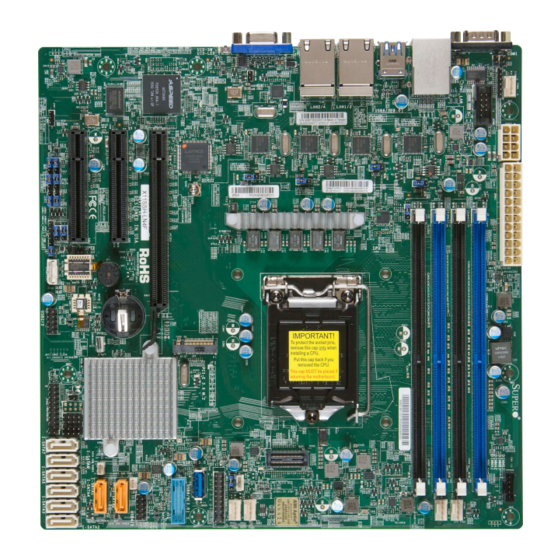
Motherboard Layout and Features
LE1
JUIDB1
BMC
LED BMC
JBR1
JPG1
JPL4
JPB1
JPME2
IPMI CODE
JI2C1
JI2C2
X11SSH-F/-LN4F
REV:1.01
Designed in the USA
SP1
USB 2/3
BT1
J23
LE3
JBT1
JL1
Intel PCH
I-SGPIO2
I-SGPIO1
I-SATA7
USB 10
JSD2
I-SATA6
(3.0)
USB 8/9
JF1
JSD1
(3.0)
I-SATA5
I-SATA4
FAN3
I-SATA3
I-SATA2
USB 4/5
FANA
CPU Installation
Heatsink Installation
Load Plate
Thermal Paste
Load Lever
Push Down
Pin 1
North Center Edge
Turn Clockwise
to Lock
CPU Properly
Turn Counter-
Installed
clockwise to
Unlock
Connect the Heatsink Wire to
Load Lever Locked
the CPU Fan Connector
into Place
Note: Graphics shown in this quick reference guide are for illustration only. Your components may or may not look exactly the same as drawings shown in this
guide.
I
ONTACT
NFORMATION
VGA
COM 1
USB 6/7
LAN 2/4
LAN 1/3
USB 0/1
(3.0)
J7
J8
IPMI_LAN
BAR CODE
COM2
JPWR2
JPL3
JPL2
JPL1
MAC CODE
JPWR1
CPU
LED PWR
FAN2
FAN1
Front Panel Control (JF1)
1
2
Power Button
PWR
Ground
Reset Button
Reset
Ground
3.3 V
Power Fail LED
Red+
Blue+
(Blue LED Cathode)
(OH/Fan Fail)
3.3V Stby
NIC2 Activity LED
NIC1 Activity LED
3.3V Stby
ID_UID_SW/3.3V Stby
HDD LED
3.3V
FP PWRLED
X
X
Ground
NMI
19
20
F
,
OR YOUR SYSTEM TO WORK PROPERLY
PLEASE DOWNLOAD APPROPRIATE
/
/
'
DRIVERS
IMAGES
USER
S MANUAL FROM THE LINKS BELOW
• Manuals: http://www.supermicro.com/support/manuals
• Drivers & Utilities: ftp://ftp.supermicro.com/CDR_Images/CDR-X11-UP/
• Safety: http://www.supermicro.com/about/policies/safety_information.cfm
Jumpers and Connectors
Jumpers
Jumper
Description
J7
LAN4 LINK ACK (-LN4F only)
Off (Disabled)
J8
LAN3 LINK ACK (-LN4F only)
Off (Disabled)
JBR1
BIOS Recovery
Pins 1-2 (Normal)
JBT1
Clear CMOS
See Chpt. 2 in user manual
JI
2
C1/JI
2
C2
SMB to PCI Slots
Pins 2-3 (Disabled)
JPB1
BMC Enable/Disable
Pins 1-2 (Enabled)
JPG1
VGA Enable
Pins 1-2 (Enabled)
JPL1-JPL4
LAN1-LAN4 Enable (LAN3/LAN4: for -LN4F only)
Pins 1-2 (Enabled)
JPME2
Manufacturing Mode Select
Pins 1-2 (Normal)
JWD1
Watch Dog Enable
Pins 1-2 (Reset)
Connectors
Connector
Description
BT1
Onboard Battery
COM1/COM2
COM1/COM2 Port Headers
Fan1-Fan4, FanA
System/CPU Fan Headers
I-SATA0-I-SATA7
SATA 3.0 Connectors via Intel PCH (6Gb/s)
I-SGPIO 1/2
Serial_Link General Purpose I/O Connection Headers 1/2
IPMI_LAN
IPMI_Dedicated Gigabit (RJ45) Port
J23
M.2 Socket
JD1
Speaker/Power LED Indicator
JF1
Front Panel Control Header
JIPMB1
4-pin External BMC I
2
C Header (for an IPMI Card)
JL1
Chassis Intrusion Header
JOH1
Overheat LED Indicator
JPI
2
C1
Power I
2
C System Management Bus (Power SMB) Header
JPWR1
24-pin ATX Main Power Connector (Required)
JPWR2
+12V 8-pin CPU power Connector (Required)
JSD1/JSD2
SATA Disk On Module (DOM) Power Connectors
JSTBY1
Wake-On-LAN Enable Header
JTPM1
Trusted Platform Module/Port 80 Connector
JUIDB1
UID (Unit Identifi cation) Switch
LAN1-LAN4
Gigabit (RJ45) LAN Ports (LAN3/LAN4: for -LN4F only)
PCI-E (PCH) Slot 4
PCI-Express 3.0 x4in x8 Slot
PCI-E (CPU) Slot 5
PCI-Express 3.0 x8 Slot
PCI-E (CPU) Slot 6
PCI-Express 3.0 x8in x16 Slot
SP1
Internal Speaker/Buzzer
USB 0/1
Back Panel USB 2.0 Ports
USB 2/3
Front Accessible USB 2.0 Headers
USB 4/5
Front Accessible USB 2.0 Headers
USB 6/7
Back Panel USB 3.0 Ports
USB 8/9
Front Accessible USB 3.0 Header
USB 10
USB 3.0 Type-A Header
VGA
Back Panel VGA Port
Note: Refer to Chapter 1 of the User Manual for detailed information on jumpers, connectors,
and LED indicators.
P
ACKAGE
• One (1) Supermicro Motherboard
:
• Six (6) SATA Cables
• One (1) I/O Shield
• One (1) Quick Reference Guide
LED Indicators
LED Indicators
Default Setting
LED
Description
LE1
Rear UID LED
LE3
PCI-E 3.0 M.2 LED
LEDBMC
BMC Heartbeat LED
LEDPWR
Onboard Power LED
Memory Support
The X11SSH-F_(-LN4F) has four (4) 288-pin DIMM slots that support up to 64GB
of SDRAM 72-bit DDR4 unbuffered ECC 2133/1866/1600/1333MHz memory.
DIMM Memory Installation
Memory Population Guidelines
Please follow the table below when populating the X11SSH-F_(-LN4F):
Memory Module Population
DIMM Slots
POR Speeds
DIMM Type
per Channel
(MHz)
Unbuffered
2133, 1866,
2
DDR4 ECC
1600, 1333
Insert the desired number of DIMMs into the memory slots. The DIMM slots
should be populated in the following order: DIMMB2, DIMMA2, DIMMB1,
DIMMA1. For the system to work properly, please use memory modules of the
same type and speed in the motherboard.
Channel A Slot 1
Channel A Slot 2
(Blue Slot)
Channel B Slot 1
Channel B Slot 2
(Blue Slot)
Release Tabs
Back Panel I/O Connectors
B
A
D
C
I/O Back Panel
A. COM1
D. USB Port 1 (2.0)
B. IPMI LAN
E. USB Port 6 (3.0)
C. USB Port 0 (2.0)
F. USB Port 7 (3.0)
Note: Refer to Chapter 2 of the User Manual for detailed information on memory support and CPU/
motherboard installation instructions.
C
ONTENTS
State
Status
Blue: On
Unit Identifi ed
Green: Blinking
Active
Green: Blinking
BMC Normal
Green: Solid on
Power On
Ranks per
Layer
Supported
FW Base
DIMM
Count
Voltage
SR, DR
6
SPS
1.2V
1
Towards the CPU
Notches
Press both notches
straight down into
the memory slot.
J
I
F
G
L
E
H
K
G. LAN 1
J. LAN 4 (-LN4F only)
H. LAN 2
K. VGA
I. LAN 3 (-LN4F only)
L. UID Switch
Advertisement


Need help?
Do you have a question about the X11SSH-F and is the answer not in the manual?
Questions and answers