Table of Contents
Advertisement
Quick Links
Advertisement
Table of Contents

Related Manuals for Supermicro X11SSL-CF


Summary of Contents for Supermicro X11SSL-CF
- Page 1 X11SSL-CF X11SSL-nF USER MANUAL Revision 1.0...
- Page 2 State of California, USA. The State of California, County of Santa Clara shall be the exclusive venue for the resolution of any such disputes. Supermicro's total liability for all claims will not exceed the price paid for the hardware product.
- Page 3 About This Manual This manual is written for system integrators, IT technicians and knowledgeable end users. It provides information for the installation and use of the X11SSL-CF/-nF motherboard. About This Motherboard The Super X11SSL-CF/-nF motherboard supports an Intel Xeon E3-1200 v5, 6th-Gen Core i3, Pentium, or Celeron processor in an LGA 1151 (H4) socket.
- Page 4 X11SSL-CF/-nF User Manual Contacting Supermicro Headquarters Address: Super Micro Computer, Inc. 980 Rock Ave. San Jose, CA 95131 U.S.A. Tel: +1 (408) 503-8000 Fax: +1 (408) 503-8008 Email: marketing@supermicro.com (General Information) support@supermicro.com (Technical Support) Website: www.supermicro.com Europe Address: Super Micro Computer B.V.
-
Page 5: Table Of Contents
Preface Table of Contents Chapter 1 Introduction 1.1 Checklist ..........................7 Quick Reference .......................11 Quick Reference Table ......................12 Motherboard Features .......................14 1.2 Processor and Chipset Overview ..................18 1.3 Special Features ........................18 1.4 System Health Monitoring ....................19 Onboard Voltage Monitors ....................19 Fan Status Monitor with Firmware Control ...............19 Environmental Temperature Control .................19 System Resource Alert......................19 1.5 ACPI Features ........................19... - Page 6 X11SSL-CF/-nF User Manual System Boot Failure .......................64 Memory Errors ........................64 Losing the System's Setup Configuration .................65 When the System Becomes Unstable ................65 3.2 Technical Support Procedures ...................67 3.3 Frequently Asked Questions ....................68 3.4 Battery Removal and Installation ..................69 Battery Removal ........................69 Proper Battery Disposal ....................69...
-
Page 7: Chapter 1 Introduction
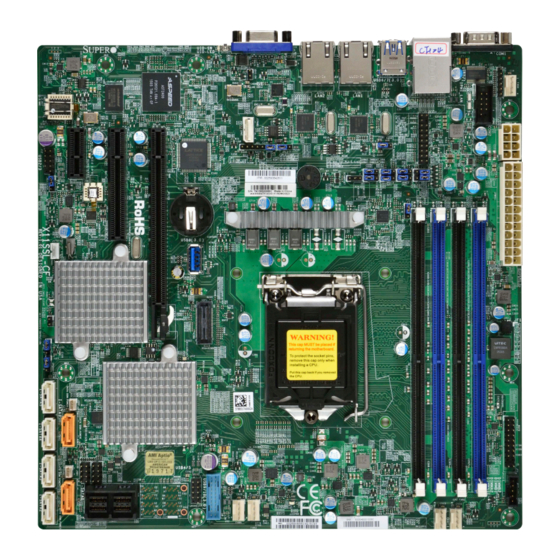
• Product safety info: http://www.supermicro.com/about/policies/safety_information.cfm • If you have any questions, please contact our support team at: support@supermicro.com This manual may be periodically updated without notice. Please check the Supermicro website for possible updates to the manual revision level. - Page 8 X11SSL-CF/-nF User Manual Figure 1-1. X11SSL-CF Motherboard Image Note: All graphics shown in this manual were based upon the latest PCB revision available at the time of publication of the manual. The motherboard you received may or may not look exactly the same as the graphics shown in this manual.
- Page 9 Chapter 1: Introduction Figure 1-2. X11SSL-nF Motherboard Image...
- Page 10 X11SSL-CF/-nF User Manual Figure 1-3. X11SSL-CF/-nF Motherboard Layout (not drawn to scale) LAN 2 USB 6/7 LAN 1 USB 0/1 COM1 (3.0) FAN4 IPMI_LAN LED BMC COM2 JTPM1 JPL1 JPL2 JPG1 JPME2 JI2C2 IPMI CODE JBR1 JPB1 JI2C1 BAR CODE X11SSL-CF_(-nF) USB 8 (3.0)
-
Page 11: Quick Reference
Chapter 1: Introduction Quick Reference IPMI_LAN JUIDB1 USB0/1 LAN1 COM1 LAN2 USB6/7 LAN 2 USB 6/7 LAN 1 USB 0/1 COM1 (3.0) JOH1 FAN4 FAN4 LEDBMC COM2 IPMI_LAN LED BMC JPME2 JIPMB1 JPL2 JPL1 COM2 JTPM1 JPWR2 JPL1 JTPM1 JPG1 USB2/3 JPL2 JI2C2... -
Page 12: Quick Reference Table
Power I2C System Management Bus (Power SMB) Header JPWR1 24-pin ATX Main Power Connector (Required) JPWR2 +12V 8-pin CPU Power Connector (Required) JSAS1 Two (2) Mini-SAS HD Ports (X11SSL-CF Only) JSD1/JSD2 SATA Disk On Module (DOM) Power Connectors JSTBY1 Wake-On-LAN Enable Header JTPM1... - Page 13 Chapter 1: Introduction Connector Description LAN1/LAN2 Gigabit (RJ45) LAN Ports PCI-E (CPU) Slot 6 PCI-Express 3.0 x8 in x16 Slot PCI-E (PCH) Slot 5 PCI-Express 3.0 x4 in x8 Slot PCI-E (PCH) Slot 4 PCI-Express 3.0 x1 Slot Internal Speaker/Buzzer USB 0/1 Back Panel USB 2.0 Ports USB 2/3, USB 4/5...
-
Page 14: Motherboard Features
• 16GB, 8GB, and 4GB, up to 64GB at 1.2V Note 1: Memory speed support depends on the processors used in the system. Note 2: For the latest CPU/memory updates, please refer to our website at http://www.supermicro.com/products/ motherboard. Chipset •... - Page 15 Chapter 1: Introduction Motherboard Features Peripheral Devices • Two (2) USB 2.0 ports on the rear I/O panel (USB 0/1) • Two (2) front accessible USB 2.0 headers (USB 2/3, USB 4/5) • Two (2) USB 3.0 ports on the rear I/O panel (USB 6/7) •...
- Page 16 Note 1: The CPU maximum thermal design power (TDP) is subject to chassis and heatsink cooling restrictions. For proper thermal management, please check the chas- sis and heatsink specifications for proper CPU TDP sizing. Note 2: For IPMI configuration instructions, please refer to the Embedded IPMI Con- figuration User's Guide available at http://www.supermicro.com/support/manuals/.
- Page 17 Chapter 1: Introduction Figure 1-4. Chipset Block Diagram IMVP 8 #A-2 3 PHASE #A-1 for Vcore #B-2 #B-1 PCI-E X8 Gen3 SLOT6 PCIe3.0 x8 #0-7 CHANNEL A Skt-H4 LGA1151 PCI-E X8 Gen3 CHANNEL B PCI-E X8 Gen3 #8-15 DMI3 LSI3008 Switch PCI-E X8 Gen3 DMI3 x4...
-
Page 18: Processor And Chipset Overview
1.2 Processor and Chipset Overview Built upon the functionality and capability of the Intel E3-1200 v5 series processors (Socket LGA 1151) and the Intel C232 PCH, the X11SSL-CF/-nF motherboard offers maximum I/O expandability, energy efficiency, and data reliability in a 14-nm process architecture, and is optimized for embedded storage solutions, networking applications, or cloud-computing platforms. -
Page 19: System Health Monitoring
Chapter 1: Introduction 1.4 System Health Monitoring This motherboard has an onboard Baseboard Management Controller (BMC) chip that supports system health monitoring. Onboard Voltage Monitors An onboard voltage monitor will scan the voltages of onboard chipset, memory, CPU, and battery continuously. Once a voltage becomes unstable, a warning is given, or an error message is sent to the screen. -
Page 20: Power Supply
As with all computer products, a stable power source is necessary for proper and reliable operation. It is even more important for processors that have high CPU clock rates. The X11SSL-CF/-nF motherboard accommodates 24-pin ATX power supplies. Although most power supplies generally meet the specifications required by the CPU, some are inadequate.
Need help?
Do you have a question about the X11SSL-CF and is the answer not in the manual?
Questions and answers