Table of Contents

Related Manuals for FDS FD201CV-C-1


Summary of Contents for FDS FD201CV-C-1
- Page 1 Revision Date: Rev: Document Number: 05/05/2017 MAN – FD201CV-C-1 Page 1 of 16 Installation and Operation Manual FD201CV-C-1 20” LCD Display © 2017 FDS Avionics Corp. TECHNICAL SUPPORT All Rights Reserved. 470-239-7421 or FDSAvionics.com...
-
Page 2: Table Of Contents
Operation Instructions ........................9 Button Control ..........................9 Composite Video Control Buttons ..................10 Installation Drawings ......................11-13 Technical Support ........................14 Instructions for Continued Airworthiness ................14 Warranty ............................15 Log of Revisions .........................16 © 2017 FDS Avionics Corp. TECHNICAL SUPPORT All Rights Reserved. 470-239-7421 or FDSAvionics.com... -
Page 3: General Information
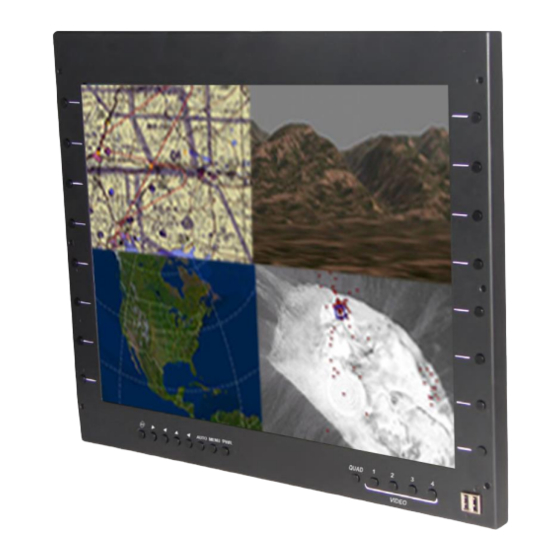
Front View Additional Information The FD201CV-C-1 utilizes a state of the art digital video decoding chipset for the analog video input. Two video sources are activated: the VGA (computer graphics i.e. moving maps) and composite video (i.e. camera inputs). -
Page 4: Specifications
Power This is a 28VDC monitor that requires 2.2 Amps of power to operate. The unit turns on automatically upon power application. © 2017 FDS Avionics Corp. TECHNICAL SUPPORT All Rights Reserved. 470-239-7421 or FDSAvionics.com... -
Page 5: Wiring Suggestions
75 Ohm video isolation transformer such as Deerfield Laboratory, Inc. Part No. 162-1 (www.deerfieldlab.com, (650) 632-4090). In most cases this should be added to the video output of the source. © 2017 FDS Avionics Corp. TECHNICAL SUPPORT All Rights Reserved. -
Page 6: Vga Wiring
We recommend coax cables be terminated using solder sleeve coaxial cable terminators such as Raychem Part Number CWT-4174-W122-5/9. Power and Ground Wiring 20 AWG wire is recommended for Power and Ground applications. © 2017 FDS Avionics Corp. TECHNICAL SUPPORT All Rights Reserved. 470-239-7421 or FDSAvionics.com... -
Page 7: Power/Video
Document Number: 05/05/2017 MAN – FD201CV-C-1 Page 7 of 16 Power/Video Pin out for FD201CV-C-1 1, 2, 3, 4 – Standard NTSC (Shield + Signal) 5, 6 – See pinouts below 7 – Standard USB (Type B) Pin out for VGA/S-VID (5) - Page 8 Revision Date: Rev: Document Number: 05/05/2017 MAN – FD201CV-C-1 Page 8 of 16 Pin out for PWR (6) Description Number 28VDC Power 28VDC Ground 28VDC Power 28VDC Ground © 2017 FDS Avionics Corp. TECHNICAL SUPPORT All Rights Reserved. 470-239-7421 or FDSAvionics.com...
-
Page 9: Operation Instructions
MAN – FD201CV-C-1 Page 9 of 16 Operation Instructions The FD201CV-C-1 is continuously on but can be de-energized by removing power from the entertainment system. No pilot or aircrew action is necessary during flight or ground operation. The operator will be able to change the video output from the FD201CV-C using the video source select button on the display. -
Page 10: Composite Video Control Buttons
Page 10 of 16 Composite Video Control Buttons Four composite video inputs can be viewed through the FD201CV-C-1. The operator can choose between a quad screen of four composite images at one time, or a full screen image of any one of the composite inputs. -
Page 11: Installation Drawings
Revision Date: Rev: Document Number: 05/05/2017 MAN – FD201CV-C-1 Page 11 of 16 Installation Drawing © 2017 FDS Avionics Corp. TECHNICAL SUPPORT All Rights Reserved. 470-239-7421 or FDSAvionics.com... - Page 12 Revision Date: Rev: Document Number: 05/05/2017 MAN – FD201CV-C-1 Page 12 of 16 © 2017 FDS Avionics Corp. TECHNICAL SUPPORT All Rights Reserved. 470-239-7421 or FDSAvionics.com...
- Page 13 Revision Date: Rev: Document Number: 05/05/2017 MAN – FD201CV-C-1 Page 13 of 16 © 2017 FDS Avionics Corp. TECHNICAL SUPPORT All Rights Reserved. 470-239-7421 or FDSAvionics.com...
-
Page 14: Technical Support
05/05/2017 MAN – FD201CV-C-1 Page 14 of 16 Technical Support Should you have any questions concerning this product or other FDS Avionics Corp. products, please contact our Product Support representatives at 470-239-7421. FDS Avionics Corp. 6435 Shiloh Road Alpharetta, GA 30005... -
Page 15: Warranty
This warranty is not transferable. Any implied warranties expire at the express limited warranty expiration date. FDS shall not be held liable for any indirect, special, punitive, incidental or consequential damages. Some states do not allow limitation on the length of an implied warranty. In such states, the exclusions or limitations of this limited warranty may not apply. -
Page 16: Log Of Revisions
Initial Release 09/21/2009 2,11 Update testing and warranty info 08/10/2010 Warranty info, Format Change 08/28/2012 Update format, warranty and non-PMA info 5/5/2017 New Format, new Company Name, Warranty © 2017 FDS Avionics Corp. TECHNICAL SUPPORT All Rights Reserved. 470-239-7421 or FDSAvionics.com...
Need help?
Do you have a question about the FD201CV-C-1 and is the answer not in the manual?
Questions and answers