Table of Contents
Advertisement
Quick Links
Advertisement
Table of Contents

Related Manuals for FDS FD141CV-C-3


Summary of Contents for FDS FD141CV-C-3
- Page 1 Revision Date: Rev: Document Number: 04/27/2017 MAN – FD141CV-C-3 Page 1 of 16 Installation and Operation Manual FD141CV-C-3 14” Widescreen HD Display © 2017 FDS Avionics Corp. TECHNICAL SUPPORT All Rights Reserved. 470-239-7421 or FDSAvionics.com...
-
Page 2: Table Of Contents
HDSDI Inputs Pinout ......................10 Rear View of Monitor with Connectors ................10 Button Control ........................11 Technical Drawing......................12-13 Technical Support ........................14 Instructions for Continued Airworthiness ..............14 Warranty ..........................15 Revisions Log ........................16 © 2017 FDS Avionics Corp. TECHNICAL SUPPORT All Rights Reserved. 470-239-7421 or FDSAvionics.com... -
Page 3: General Information
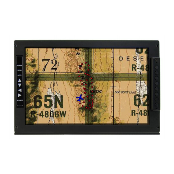
Page 3 of 16 General Information The FD141CV-C-3 is a 14” High Definition LCD. This monitor includes four video source inputs: (1) HDSDI, (1) DVI Computer input, (1) VGA Computer Graphics input such as Moving Map CPU, and (1) Composite NTSC/PAL. In addition, there is (1) HDSDI Loop through Driver Output. -
Page 4: Specifications
All cabin equipment, such as the FD141CV-C-3, should be installed on a non-essential bus and have a dedicated circuit breaker. The FD141CV-C-3 is designed to mount onto a ruggedized articulating arm or into a standard electronics rack using (2) 10-32 Machine screws. See installation drawing on page 18 for measurement details. -
Page 5: Wiring Suggestions
Avoid routing video wiring parallel to: AC wiring Strobe wiring DC motor supply cables Inverter cabling Or any other potential noise source. © 2017 FDS Avionics Corp. TECHNICAL SUPPORT All Rights Reserved. 470-239-7421 or FDSAvionics.com... -
Page 6: Power And Ground Wiring
Also, use short heavy gauge wire and a clean tight connection for ground. It is the installer's responsibility to understand the product's requirements to install the product in compliance with industry standards and safety. © 2017 FDS Avionics Corp. TECHNICAL SUPPORT All Rights Reserved. -
Page 7: Power/Composite Pinout
Standard Density DB-25 Receptacle – (supplied) Connector P/N: M24308/2-283 or Equivalent Crimp Contacts P/N: M39029/63-368 or Equivalent Description Number 15-28VDC Power 15-28VDC Ground Composite Video Signal Composite Video Return © 2017 FDS Avionics Corp. TECHNICAL SUPPORT All Rights Reserved. 470-239-7421 or FDSAvionics.com... -
Page 8: Dvi Pinout
TMDS data 1 shield +5 V Ground Hot plug detect TMDS data 0- TMDS data 0+ TMDS data 0 shield TMDS clock shield TMDS clock+ TMDS clock- © 2017 FDS Avionics Corp. TECHNICAL SUPPORT All Rights Reserved. 470-239-7421 or FDSAvionics.com... -
Page 9: Vga Pinout
Red Video Green Video Blue Video Ground Ground (DDC Return) Red Ground Green Ground Blue Ground Sync Ground Ground DDC Data Horizontal Sync Vertical Sync DDC Clock © 2017 FDS Avionics Corp. TECHNICAL SUPPORT All Rights Reserved. 470-239-7421 or FDSAvionics.com... -
Page 10: Hdsdi Inputs Pinout
MAN – FD141CV-C-3 Page 10 of 16 HDSDI Inputs HDSDI Loop-through Standard 75Ω BNC Plug (RG179 connectors supplied) Description Center Video Signal Shell Video Return Rear View with Connectors © 2017 FDS Avionics Corp. TECHNICAL SUPPORT All Rights Reserved. 470-239-7421 or FDSAvionics.com... -
Page 11: Button Control
Page 11 of 16 Button Controls Located on the front-right side of the FD141CV-C-3 are 8 buttons. Their corresponding labels are located on the left side of the monitor. These buttons are used to power up the unit and navigate through the different menus. The menu button is used as a toggle, push to view the menu screens, push again to exit. -
Page 12: Technical Drawing
Revision Date: Rev: Document Number: 04/27/2017 MAN – FD141CV-C-3 Page 12 of 16 Technical Drawing © 2017 FDS Avionics Corp. TECHNICAL SUPPORT All Rights Reserved. 470-239-7421 or FDSAvionics.com... -
Page 13: Technical Drawing
Revision Date: Rev: Document Number: 04/27/2017 MAN – FD141CV-C-3 Page 13 of 16 Technical Drawing © 2017 FDS Avionics Corp. TECHNICAL SUPPORT All Rights Reserved. 470-239-7421 or FDSAvionics.com... -
Page 14: Technical Support
04/27/2017 MAN – FD141CV-C-3 Page 14 of 16 Technical Support Should you have any questions concerning this product or other FDS Avionics Corp. products, please contact our Product Support representatives at (470) 239-7421. FDS Avionics Corp. 6435 Shiloh Road Alpharetta, GA 30005... -
Page 15: Warranty
This warranty is not transferable. Any implied warranties expire at the express limited warranty expiration date. FDS shall not be held liable for any indirect, special, punitive, incidental or consequential damages. Some states do not allow limitation on the length of an implied warranty. In such states, the exclusions or limitations of this limited warranty may not apply. -
Page 16: Revisions Log
Revision Date: Rev: Document Number: 04/27/2017 MAN – FD141CV-C-3 Page 16 of 16 Revisions Log Date Page Description 02/14/2014 Initial Release 4/27/2017 Company name change, Warranty, and formatting. © 2017 FDS Avionics Corp. TECHNICAL SUPPORT All Rights Reserved. 470-239-7421 or FDSAvionics.com...
Need help?
Do you have a question about the FD141CV-C-3 and is the answer not in the manual?
Questions and answers