
Related Manuals for FDS FD171CV-C-1


Summary of Contents for FDS FD171CV-C-1
- Page 1 Revision Date: Rev: Document Number: 10/12/2011 MAN – FD171CV-C-1 Page 1 of 16 Installation and Operation Manual FD171CV-C-1 17” LCD Monitor...
-
Page 2: Table Of Contents
Revision Date: Rev: Document Number: 10/12/2011 MAN – FD171CV-C-1 Page 2 of 16 Table of Contents General Information ........................3 1. Front View ..........................3 2. Additional Information ....................3 Specifications ..........................4 Installation Instructions ......................4 1. Power ..........................4 Wiring Instructions ........................6 1. S-Video and Audio Wiring ....................5 2. -
Page 3: General Information
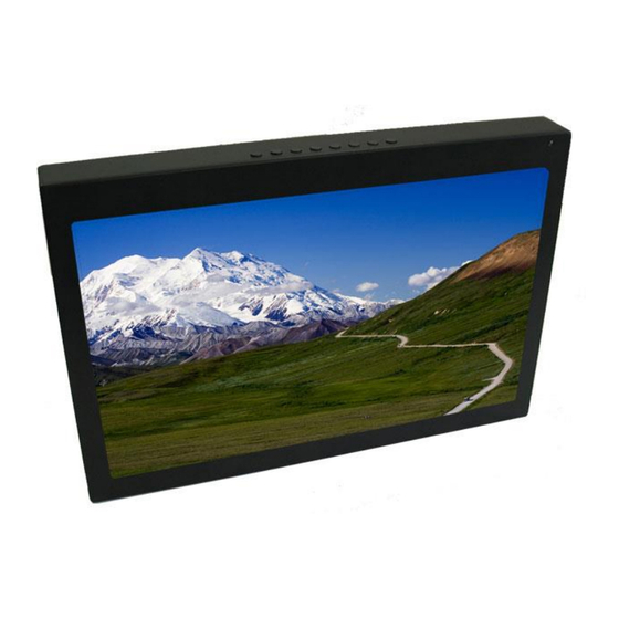
Page 3 of 16 General Information The FD171CV-C-1 is a panel mounted 17” monitor. Built with retrofit aircraft integration in mind, this display can switch between five video input sources using an infrared remote control or with the buttons located on the top of the unit. -
Page 4: Specifications
DO-160, Sec 7, 8 Installation Instructions All cabin equipment, such as the FD171CV-C-1, should be installed on a non-essential bus and have a dedicated circuit breaker. It is a requirement that a switch be installed in the cockpit so that the pilot can de-energize the system should it become necessary. -
Page 5: S-Video And Audio Wiring
Revision Date: Rev: Document Number: 10/12/2011 MAN – FD171CV-C-1 Page 5 of 16 Wiring Suggestions For balanced signals on twisted pair cable, all shields should be grounded to the connector at the source, and floating at the display. Avoid routing video wiring parallel to: ... -
Page 6: Wiring Instructions
Revision Date: Rev: Document Number: 10/12/2011 MAN – FD171CV-C-1 Page 6 of 16 VGA Wiring Recommended cable for VGA purpose is ECS P/N 453005. This is a single shielded cable containing 5 separate coaxial cables, color-coded to match the functions of the wires. -
Page 7: Power And Ground Wiring
Revision Date: Rev: Document Number: 10/12/2011 MAN – FD171CV-C-1 Page 7 of 16 Power and Ground Wiring 20 AWG wire is recommended for Power and Ground applications. This is a 28VDC monitor that requires 3 amps of power to operate. To operate properly this monitor requires an input voltage of 24-29VDC. -
Page 8: Power/Video
Revision Date: Rev: Document Number: 10/12/2011 MAN – FD171CV-C-1 Page 8 of 16 Rear View with Connectors VGA Video Pin out for DB-15 Female Connector (Industry Standard VGA) Connector P/N: 748364-1 or Equivalent Crimp Contacts P/N: M39029/58-360 or Equivalent Description... -
Page 9: Power Pin Out
Revision Date: Rev: Document Number: 10/12/2011 MAN – FD171CV-C-1 Page 9 of 16 Pin out for 28V PWR – D38999 connector (supplied) Mating Connector P/N: D38999/26FB5SA or Equivalent Crimp Contacts P/N: M39029/56-351 or Equivalent MATING FACE Description Number 28VDC Power... -
Page 10: Composite Pin Out
Revision Date: Rev: Document Number: 10/12/2011 MAN – FD171CV-C-1 Page 10 of 16 Pin out for Composite Video (Standard BNC – 75 OHM) – 31-242 (Supplied) Description Center C Signal Shell C Return Pin out for DVI-D Accepts a standard DVI-D (Single Link) male connector (supplied) -
Page 11: Operation Instructions
The FD171CV-C-1 is continuously on but can be de-energized by removing power from the video system. No pilot or aircrew action is necessary during flight or ground operation. The operator will be able to change the video output from the FD171CV-C-1 using the video source select button on the display. -
Page 12: Technical Drawing
Revision Date: Rev: Document Number: 10/12/2011 MAN – FD171CV-C-1 Page 12 of 16 Technical Drawing © 2015 Flight Display Systems. TECHNICAL SUPPORT All Rights Reserved. 470-239-7421 or FlightDisplay.com... -
Page 13: Troubleshooting
Revision Date: Rev: Document Number: 10/12/2011 MAN – FD171CV-C-1 Page 13 of 16 Troubleshooting VGA Shadowing Most of shadowing problems are due to shielding on the wire. Locate the point where all of the shields are connected. Cut away the shields, one at a time, while viewing the display on the screen to observe which shield is causing the noise. -
Page 14: Technical Support
For further product information, technical data and sample wiring diagrams, please click on the Dealers section of our web site at www.FlightDisplay.com Instructions for Continued Airworthiness The FD171CV-C-1 is designed not to require regular general maintenance. © 2015 Flight Display Systems. TECHNICAL SUPPORT All Rights Reserved. -
Page 15: Warranty
This warranty is not transferable. Any implied warranties expire at the express limited warranty expiration date. FDS shall not be held liable for any indirect, special, punitive, incidental or consequential damages. Some states do not allow limitation on the length of an implied warranty. In such states, the exclusions or limitations of this limited warranty may not apply. -
Page 16: Log Of Revisions
Revision Date: Rev: Document Number: 10/12/2011 MAN – FD171CV-C-1 Page 16 of 16 Log of Revisions Date Page Description 09/27/11 Initial Release 10/05/11 5,13 Updated Specifications, Technical Drawing 10/12/11 Revised Technical Drawing © 2015 Flight Display Systems. TECHNICAL SUPPORT All Rights Reserved.
Need help?
Do you have a question about the FD171CV-C-1 and is the answer not in the manual?
Questions and answers