Table of Contents
Advertisement
Quick Links
Advertisement
Table of Contents

Related Manuals for FDS FD215CV-C-7


Summary of Contents for FDS FD215CV-C-7
- Page 1 Revision Date: Rev: Document Number: 01/10/2017 MAN – FD215CV-C-7 Page 1 of 25 Installation and Operation Manual FD215CV-C-7 21.5” Widescreen HD Display © 2017 FDS Avionics Corp. TECHNICAL SUPPORT All Rights Reserved. 470-239-7421 or FDSAvionics.com...
-
Page 2: Table Of Contents
Operation Instructions ......................14 Button Control ..........................15 Quad Screen or Full Screen....................16-21 Technical Drawing........................22 Technical Support ........................23 Instructions for Continued Airworthiness ................23 Warranty ...........................24 Log of Revisions ........................25 © 2017 FDS Avionics Corp. TECHNICAL SUPPORT All Rights Reserved. 470-239-7421 or FDSAvionics.com... -
Page 3: General Information
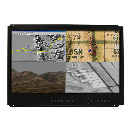
MAN – FD215CV-C-7 Page 3 of 25 General Information The FD215CV-C-7 is a special mission HD monitor which is designed to be mounted in a standard 19-inch rack. This display includes quad screen vide with picture in picture (PIP) Capability. -
Page 4: Specifications
Materials Aluminum Installation Instructions All cabin equipment, such as the FD215CV-C-7, should be installed on a non-essential bus and have a dedicated circuit breaker. The FD215CV-C-7 is designed to mount into a standard electronics rack using (4) 10-32 Machine screws. See installation drawing on page 16 for measurement details. -
Page 5: Wiring Suggestions
Inverter cabling Or any other potential noise source. We recommend coax cables be terminated using solder sleeve coaxial cable terminators such as Raychem Part Number CWT-4174-W122-5/9. © 2017 FDS Avionics Corp. TECHNICAL SUPPORT All Rights Reserved. 470-239-7421 or FDSAvionics.com... -
Page 6: Power And Ground Wiring
Also, use short heavy gauge wire and a clean tight connection for ground. It is the installer's responsibility to understand the product's requirements to install the product in compliance with industry standards and safety. © 2017 FDS Avionics Corp. TECHNICAL SUPPORT All Rights Reserved. -
Page 7: Rear View With Connectors
Page 7 of 25 Rear View with Connectors VGA INPUT 28 VDC INPUT SDI OUTPUT DVI-D INPUT CONTROL (FROM QUAD) SDI INPUTS (4) PORT BOARD) HDDSI OUT © 2017 FDS Avionics Corp. TECHNICAL SUPPORT All Rights Reserved. 470-239-7421 or FDSAvionics.com... -
Page 8: Power/Video
Pin out for 28V PWR – D38999 connector (supplied) Connector P/N: D38999/26FB5SA or Equivalent Crimp Contacts P/N: M39029/56-351 or Equivalent MATING FACE Description Number 28VDC Power 28VDC Power 28VDC Ground 28VDC Ground © 2017 FDS Avionics Corp. TECHNICAL SUPPORT All Rights Reserved. 470-239-7421 or FDSAvionics.com... -
Page 9: Vga Video Pin Out
Number Red Video Green Video Blue Video Reserved H-Sync Ground Red Return Green Return Blue Return +5V DC V-Sync Ground Reserved Reserved Horizontal Sync Vertical Sync Reserved © 2017 FDS Avionics Corp. TECHNICAL SUPPORT All Rights Reserved. 470-239-7421 or FDSAvionics.com... -
Page 10: Pin Out
*Add jumper wires for DVI video selection. Remove jumper wires for VGA video selection. Maximum jumper wire length is 2”. Pin out for HD-SDI Inputs (Standard BNC – 75 OHM) – 31-242 Description Center Video Signal Shell Video Return © 2017 FDS Avionics Corp. TECHNICAL SUPPORT All Rights Reserved. 470-239-7421 or FDSAvionics.com... - Page 11 TMDS data 1 shield +5 V Ground Hot plug detect TMDS data 0- TMDS data 0+ TMDS data 0 shield TMDS clock shield TMDS clock+ TMDS clock- © 2017 FDS Avionics Corp. TECHNICAL SUPPORT All Rights Reserved. 470-239-7421 or FDSAvionics.com...
-
Page 12: How To Change From Vga (Analog) To Dvi (Digital) Inputs
Press and hold down the DOWN ARROW button (after several seconds, this menu will open on the monitor display) Press the down arrow button 3 times until the following screen is displayed: © 2017 FDS Avionics Corp. TECHNICAL SUPPORT All Rights Reserved. - Page 13 If VGA is chosen the screen will look like this: To switch over to Digital just disable the Analog and Enable the Digital. The screen will look like this: © 2017 FDS Avionics Corp. TECHNICAL SUPPORT All Rights Reserved. 470-239-7421 or FDSAvionics.com...
-
Page 14: Operation Instructions
No pilot or aircrew action is necessary during flight or ground operation. The operator will be able to change the video display on the FD215CV-C-7 by pressing the computer button to select the VGA or DVI input as programmed. HD-SDI inputs can be selected by pressing buttons 1 through 4. -
Page 15: Button Control
Page 15 of 25 Button Controls Located on the front right of the FD215CV-C-7 are two sets of 4 buttons. These buttons are used to power up the unit and navigate through the different menus. The menu button is used as a toggle, push to view the menu screens, push again to exit. -
Page 16: Quad Screen Or Full Screen
This display has the capability to display a quad screen or full screen from any of the four HDSDI inputs. The image seen here is the bottom view of the FD215CV-C-7 LCD. Connecting the SDI input to the output of the attached quad box on the unit will enable the operator to view any image from any of the connected screens on board the aircraft. - Page 17 Cannot have the computer source displayed within both the Main and the PIP windows at same time. Cannot have a video source (1, 2, 3, 4 or QUAD) displayed within both the Main and the PIP windows at same time. © 2017 FDS Avionics Corp. TECHNICAL SUPPORT All Rights Reserved. 470-239-7421 or FDSAvionics.com...
- Page 18 Long Press (LP) of COMP moves that computer input to Main and turns PIP Off o Returning to PIP with COMP in the Main window, displays the last used video input in the PIP window © 2017 FDS Avionics Corp. TECHNICAL SUPPORT All Rights Reserved.
- Page 19 With PIP On: Swaps sources between Main window and PIP window o With PIP Off: Swaps sources (computer or video) on the Main window © 2017 FDS Avionics Corp. TECHNICAL SUPPORT All Rights Reserved.
- Page 20 Long Press (LP) moves that video source to the Main window and turns PIP Off o Returning to PIP with the selected video source (1, 2, 3, or 4) in the Main window, displays COMP in the PIP window © 2017 FDS Avionics Corp. TECHNICAL SUPPORT All Rights Reserved.
- Page 21 Long Press moves QUAD video input to Main and turns PIP Off o Returning to PIP with QUAD in the Main window, displays COMP in the PIP window © 2017 FDS Avionics Corp. TECHNICAL SUPPORT All Rights Reserved. 470-239-7421 or FDSAvionics.com...
-
Page 22: Technical Drawing
Revision Date: Rev: Document Number: 01/10/2017 MAN – FD215CV-C-7 Page 22 of 25 Technical Drawing © 2017 FDS Avionics Corp. TECHNICAL SUPPORT All Rights Reserved. 470-239-7421 or FDSAvionics.com... -
Page 23: Technical Support
01/10/2017 MAN – FD215CV-C-7 Page 23 of 25 Technical Support Should you have any questions concerning this product or other FDS Avionics Corp. products, please contact our Product Support representatives at (470) 239-7421. FDS Avionics Corp. 6435 Shiloh Road Alpharetta, GA 30005... -
Page 24: Warranty
Limited Warranty All FDS Avionics Corp. (FDS) products are warranted to be free from material or manufacturing defects for a period of 24 months from the date of shipment for General Aviation customers or 12 months from the date of shipment for Government/Special Mission customers. -
Page 25: Log Of Revisions
Pinout information changed; Additional instruction on changing 06/14/2013 input from Analog to Digital; Quad Button Controls Added. New Company Name and Format Change. No revision change 1/10/2017 necessary. © 2017 FDS Avionics Corp. TECHNICAL SUPPORT All Rights Reserved. 470-239-7421 or FDSAvionics.com...
Need help?
Do you have a question about the FD215CV-C-7 and is the answer not in the manual?
Questions and answers