Table of Contents

Related Manuals for FDS FD215CV-C-6


Summary of Contents for FDS FD215CV-C-6
- Page 1 Revision Date: Rev: Document Number: 01/11/2017 MAN – FD215CV-C-6 Page 1 of 16 Installation and Operation Manual FD215CV-C-6 21.5” LCD Display © 2017 FDS Avionics Corp. TECHNICAL SUPPORT All Rights Reserved. 470-239-7421 or FDSAvionics.com...
-
Page 2: Table Of Contents
Technical Drawing ...................... 11 Operation Instructions ....................12 Button Control ......................12-13 Technical Support ....................... 14 Instructions for Continued Airworthiness ..............14 Warranty ........................15 Log of Revisions ......................16 © 2017 FDS Avionics Corp. TECHNICAL SUPPORT All Rights Reserved. 470-239-7421 or FDSAvionics.com... -
Page 3: General Information
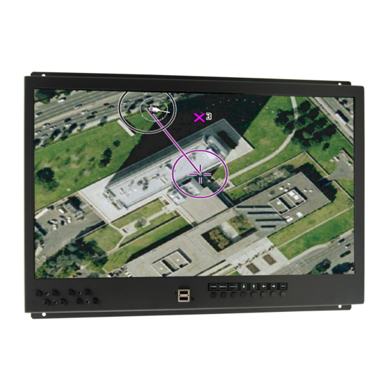
01/11/2017 MAN – FD215CV-C-6 Page 3 of 16 General Information The FD215CV-C-6 is a special mission monitor which has features that allow installation in a standard rack mount configuration. Front View Additional Information The FD215CV-C-6 utilizes a state of the art digital video decoding chipset for the analog video input. -
Page 4: Specifications
Materials Aluminum Installation Instructions All cabin equipment, such as the FD215CV-C-6, should be installed on a non-essential bus and have a dedicated circuit breaker. The FD215CV-C-6 is designed to mount into a standard electronics rack using (4) 10-32 Machine screws. See installation drawing on page 13 for measurement details. -
Page 5: Wiring Instructions
Deerfield Laboratory, Inc. Part No. 162-1 (www.deerfieldlab.com, (650) 632-4090). In most cases this should be added to the video output of the source. © 2017 FDS Avionics Corp. TECHNICAL SUPPORT All Rights Reserved. 470-239-7421 or FDSAvionics.com... -
Page 6: Vga Wiring
5 separate coaxial cables, color-coded to match the functions of the wires. We recommend coax cables be terminated using solder sleeve coaxial cable terminators such as Raychem Part Number CWT-4174-W122-5/9. © 2017 FDS Avionics Corp. TECHNICAL SUPPORT All Rights Reserved. -
Page 7: Power And Ground Wiring
NUMBER Red Video Green Video Blue Video Red Return (Ground) Green Return (Ground) Blue Return (Ground) Sync Return (Ground) DDC Data Horizontal Sync Vertical Sync DDC Clock © 2017 FDS Avionics Corp. TECHNICAL SUPPORT All Rights Reserved. 470-239-7421 or FDSAvionics.com... - Page 8 Pin out for 28V PWR – D38999 connector (supplied) Connector P/N: D38999/26FB5SA or Equivalent Crimp Contacts P/N: M39029/56-351 or Equivalent MATING FACE Description Number 28VDC Power 28VDC Power 28VDC Ground 28VDC Ground © 2017 FDS Avionics Corp. TECHNICAL SUPPORT All Rights Reserved. 470-239-7421 or FDSAvionics.com...
- Page 9 Y Signal Shell Y Return Pin out for S-Video (Chrominance - C Component) (Standard BNC – 75 OHM) – 31-242 (Supplied) Description Center C Signal Shell C Return © 2017 FDS Avionics Corp. TECHNICAL SUPPORT All Rights Reserved. 470-239-7421 or FDSAvionics.com...
- Page 10 TMDS data 1 shield +5 V Ground Hot plug detect TMDS data 0- TMDS data 0+ TMDS data 0 shield TMDS clock shield TMDS clock+ TMDS clock- © 2017 FDS Avionics Corp. TECHNICAL SUPPORT All Rights Reserved. 470-239-7421 or FDSAvionics.com...
-
Page 11: Technical Drawing
Revision Date: Rev: Document Number: 01/11/2017 MAN – FD215CV-C-6 Page 11 of 16 Technical Drawing © 2017 FDS Avionics Corp. TECHNICAL SUPPORT All Rights Reserved. 470-239-7421 or FDSAvionics.com... -
Page 12: Operation Instructions
The FD215CV-C-6 is continuously on but can be de-energized by removing power from the video system. No pilot or aircrew action is necessary during flight or ground operation. The operator will be able to change the video output from the FD215CV-C-6 using the video source select button on the display. - Page 13 Moves the highlight icon down to the function that user wants. Decreases the adjustment of the selected function. Increases the adjustment of the selected function. Selects the Input Signal among analog RGB/S- Video/Composite. © 2017 FDS Avionics Corp. TECHNICAL SUPPORT All Rights Reserved. 470-239-7421 or FDSAvionics.com...
-
Page 14: Technical Support
01/11/2017 MAN – FD215CV-C-6 Page 14 of 16 Technical Support Should you have any questions concerning this product or other FDS Avionics Corp. products, please contact our Product Support representatives at (470) 239-7421. FDS Avionics Corp. 6435 Shiloh Road Alpharetta, GA 30005... -
Page 15: Warranty
Limited Warranty All FDS Avionics Corp. (FDS) products are warranted to be free from material or manufacturing defects for a period of 24 months from the date of shipment for General Aviation customers or 12 months from the date of shipment for Government/Special Mission customers. -
Page 16: Log Of Revisions
Revisions Log Date Page Description 04/15/2013 Initial Release Address, Warranty Information, VGA Pinout and Support 06/26/2014 Numbers. Changed company name and formatting only. No revision change 1/11/2017 necessary. © 2017 FDS Avionics Corp. TECHNICAL SUPPORT All Rights Reserved. 470-239-7421 or FDSAvionics.com...
Need help?
Do you have a question about the FD215CV-C-6 and is the answer not in the manual?
Questions and answers