Table of Contents
Advertisement
Quick Links
Advertisement
Table of Contents

Related Manuals for FDS FD141CV-C-1


Summary of Contents for FDS FD141CV-C-1
- Page 1 Revision Date: Rev: Document Number: 05/04/2017 MAN – FD141CV-C-1 Page 1 of 15 Installation and Operation Manual FD141CV-C-1 14” Widescreen HD Display © 2017 FDS Avionics Corp. TECHNICAL SUPPORT All Rights Reserved. 470-239-7421 or FDSAvionics.com...
-
Page 2: Table Of Contents
Operation Instructions ......................9 Button Control ........................10 Quad Screen, Full Screen, Button Controls ..............11 Technical Drawing.......................12 Technical Support ........................13 Instructions for Continued Airworthiness ..............13 Warranty ..........................14 Revisions Log ........................15 © 2017 FDS Avionics Corp. TECHNICAL SUPPORT All Rights Reserved. 470-239-7421 or FDSAvionics.com... -
Page 3: General Information
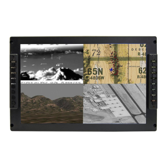
Front View Additional Information The FD141CV-C-1 utilizes a state of the art digital video decoding chipset for all video inputs. Three video sources are activated: HD-SDI, with input from an internal quad board for viewing up to 4 HD Video inputs, DVI, and VGA (for computer graphics i.e. moving maps). -
Page 4: Specifications
All cabin equipment, such as the FD141CV-C-1, should be installed on a non-essential bus and have a dedicated circuit breaker. The FD141CV-C-1 is designed to mount into a standard electronics rack using (4) 10-32 Machine screws. See installation drawing on page 18 for measurement details. -
Page 5: Vga Wiring
We recommend coax cables be terminated using solder sleeve coaxial cable terminators such as Raychem Part Number CWT-4174-W122-5/9. Power and Ground Wiring 20 AWG wire is recommended for Power and Ground applications. © 2017 FDS Avionics Corp. TECHNICAL SUPPORT All Rights Reserved. 470-239-7421 or FDSAvionics.com... -
Page 6: Power/Composite
Crimp Contacts P/N: M39029/63-368 or Equivalent PIN NUMBER DESCRIPTION 28VDC POWER 28VDC GROUND COMPOSITE VIDEO - SIGNAL COMPOSITE VIDEO - SHIELD RS232 RxD RS232 TxD RS232 GROUND © 2017 FDS Avionics Corp. TECHNICAL SUPPORT All Rights Reserved. 470-239-7421 or FDSAvionics.com... -
Page 7: Dvi-D Pinout
TMDS data 1 shield +5 V Ground Hot plug detect TMDS data 0- TMDS data 0+ TMDS data 0 shield TMDS clock shield TMDS clock+ TMDS clock- © 2017 FDS Avionics Corp. TECHNICAL SUPPORT All Rights Reserved. 470-239-7421 or FDSAvionics.com... -
Page 8: Hdsdi Inputs Pinout
Red Video Green Video Blue Video Ground Ground (DDC Return) Red Ground Green Ground Blue Ground Sync Ground Ground DDC Data Horizontal Sync Vertical Sync DDC Clock © 2017 FDS Avionics Corp. TECHNICAL SUPPORT All Rights Reserved. 470-239-7421 or FDSAvionics.com... -
Page 9: Rear View Of Monitor With Connectors
No pilot or aircrew action is necessary during flight or ground operation. The operator will be able to change the video display on the FD141CV-C-1 by pressing the computer button to select the VGA or DVI input as programmed. HD-SDI inputs will be displayed. -
Page 10: Button Control
Page 10 of 15 Button Controls Located on the front-right side of the FD141CV-C-1 are 8 buttons. These buttons are used to power up the unit and navigate through the different menus. The menu button is used as a toggle, push to view the menu screens, push again to exit. -
Page 11: Quad Screen, Full Screen, Button Controls
This monitor has the capability to display a quad screen or full screen from any of the seven inputs. The image seen here is the back view of the FD141CV-C-1 LCD. Connecting the SDI input to the output of the attached quad box on the unit will enable the operator to view any image from any of the connected screens on board the aircraft. -
Page 12: Technical Drawing
Revision Date: Rev: Document Number: 05/04/2017 MAN – FD141CV-C-1 Page 12 of 15 Technical Drawing © 2017 FDS Avionics Corp. TECHNICAL SUPPORT All Rights Reserved. 470-239-7421 or FDSAvionics.com... -
Page 13: Technical Support
05/04/2017 MAN – FD141CV-C-1 Page 13 of 15 Technical Support Should you have any questions concerning this product or other FDS Avionics Corp. products, please contact our Product Support representatives at (470) 239-7421. FDS Avionics Corp. 6435 Shiloh Road Alpharetta, GA 30005... -
Page 14: Warranty
Warranty Information All FDS Avionics Corp. products are warranted to be free from material or manufacturing defects for a period of 24 months from the date of shipment for General Aviation customers or 12 months from the date of shipment for Government/Special Mission customers. -
Page 15: Revisions Log
Document Number: 05/04/2017 MAN – FD141CV-C-1 Page 15 of 15 Revisions Log Date Page Description 11/27/2013 Initial Release 05/04/2017 All New Corporate Name, Warranty, Phone Numbers, Format © 2017 FDS Avionics Corp. TECHNICAL SUPPORT All Rights Reserved. 470-239-7421 or FDSAvionics.com...
Need help?
Do you have a question about the FD141CV-C-1 and is the answer not in the manual?
Questions and answers