Table of Contents
Advertisement
Quick Links
Advertisement
Table of Contents

Related Manuals for FDS FDPMAID Series


Summary of Contents for FDS FDPMAID Series
- Page 1 Revision Date: Rev: Document Number: 08/06/2012 MAN – FDPMAID Page 1 of 18 Installation and Operation Manual FDPMAID Advisory Information Display © 2015 Flight Display Systems. TECHNICAL SUPPORT All Rights Reserved. 470-239-7421 or FlightDisplay.com...
- Page 2 Revision Date: Rev: Document Number: 08/06/2012 MAN – FDPMAID Page 2 of 18 FDPMAID Advisory Information Display © 2006 Flight Display Systems. All Rights Reserved. Flight Display Systems 6435 Shiloh Road Alpharetta, GA 30005 +1 (470) 239-7400 Phone +1 (678) 867-6742 Fax sales@FlightDisplay.com www.FlightDisplay.com For the most current copy of all product manuals, please visit our website at...
-
Page 3: Table Of Contents
Revision Date: Rev: Document Number: 08/06/2012 MAN – FDPMAID Page 3 of 18 Table of Contents General Information ........................4 Front View ............................4 Specifications ..........................5 Installation Instructions ......................5 Mounting Hole Template ......................6 Power ..............................6 Wiring Suggestions ........................7 Comp and Audio Wiring ......................7 VGA Wiring ...........................8 Power and Ground ........................9 Dual Installment ..........................9... -
Page 4: General Information
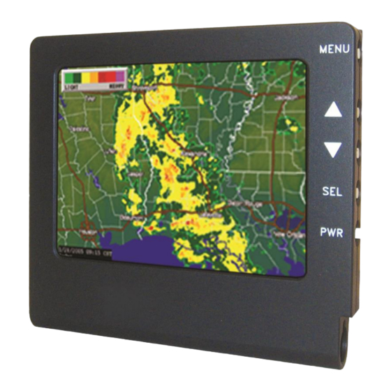
Revision Date: Rev: Document Number: 08/06/2012 MAN – FDPMAID Page 4 of 18 General Information The FDPMAID is a 5” Panel Mount Advisory Information Display, which creates panel space where none previously existed, providing an excellent opportunity to bring EVS video, satellite weather, or any other VGA/Composite source into the cockpit with a low- profile, panel mounted display. -
Page 5: Specifications
Revision Date: Rev: Document Number: 08/06/2012 MAN – FDPMAID Page 5 of 18 Additional Information The FDPMAID can be ordered as two different part numbers, depending on the desired orientation of the display. To order the display with the control buttons on the right-side of the unit, order the FDPMAID-R (shown above). - Page 6 Revision Date: Rev: Document Number: 08/06/2012 MAN – FDPMAID Page 6 of 18 The FDPMAID has four 8-32 screws that are used to mount the unit in the cockpit. In addition, there is a 0.375” diameter hole in which the data cable is protruded to run to the DEB located elsewhere.The rear mounting plate can be removed in order to relocate the mounting screws.
-
Page 7: Power
Revision Date: Rev: Document Number: 08/06/2012 MAN – FDPMAID Page 7 of 18 Power This is a 28VDC monitor that requires 1 Amps (28 Watts) of power to operate. © 2015 Flight Display Systems. TECHNICAL SUPPORT All Rights Reserved. 470-239-7421 or FlightDisplay.com... -
Page 8: Wiring Suggestions
Revision Date: Rev: Document Number: 08/06/2012 MAN – FDPMAID Page 8 of 18 Wiring Suggestions All shields should be grounded to the connector at the source, and floating at the display. Avoid routing video wiring parallel to: AC wiring ... -
Page 9: Vga Wiring
Revision Date: Rev: Document Number: 08/06/2012 MAN – FDPMAID Page 9 of 18 VGA Wiring Recommended cable for VGA purpose is ECS P/N 453005. This is a single shielded cable containing 5 separate coaxial cables, color-coded to match the functions of the wires. -
Page 10: Power And Ground
Revision Date: Rev: Document Number: 08/06/2012 MAN – FDPMAID Page 10 of 18 Power and Ground Wiring This is a 28VDC monitor that requires 0.3 amps of power to operate. To operate properly this monitor requires an input voltage of 18-29VDC. The rated current of the equipment and associated voltage drop should be taken into consideration when selecting wire gauge. -
Page 11: Power/Video
Revision Date: Rev: Document Number: 08/06/2012 MAN – FDPMAID Page 11 of 18 Power/Video Pin out for High Density DB-15 Receptacle (P1) Connector P/N: M24308/2-286 or Equivalent Crimp Contacts P/N: M39029/57-354 or Equivalent Number Description 28VDC Power 28VDC Ground Composite Video #1 - Signal Composite Video #1 - Return Composite Video #2 - Signal Composite Video #2 - Return... - Page 12 Revision Date: Rev: Document Number: 08/06/2012 MAN – FDPMAID Page 12 of 18 NOTE: On earlier versions of the Detached Electronics Box (D.E.B.) the J2 connector was a DB37; current versions now use a DB44 connector. If you are replacing an existing DB37 version D.E.B with the current DB44 version then, you will need Data/LVDS DB44 to DB37 Adapter Cable Assembly part number 620-00002-4437.
-
Page 13: Technical Drawing
Revision Date: Rev: Document Number: 08/06/2012 MAN – FDPMAID Page 13 of 18 Technical Drawing © 2015 Flight Display Systems. TECHNICAL SUPPORT All Rights Reserved. 470-239-7421 or FlightDisplay.com... -
Page 14: Operating Instructions
Revision Date: Rev: Document Number: 08/06/2012 MAN – FDPMAID Page 14 of 18 Operation Instructions When 28VDC power is applied, the FD90AID will turn on and search for video input on the last known source. If no video input is found, the display will go into standby mode. Pilots will be able to change the video output on the FD90AID using the Select button on the side of the monitor. -
Page 15: Troubleshooting
Revision Date: Rev: Document Number: 08/06/2012 MAN – FDPMAID Page 15 of 18 Troubleshooting VGA Shadowing Most of shadowing problems are due to shielding on the wire. Locate the point where all of the shields are connected. Cut away the shields, one at a time, while viewing the display on the screen to observe which shield is causing the noise. -
Page 16: Technical Support
Revision Date: Rev: Document Number: 08/06/2012 MAN – FDPMAID Page 16 of 18 Technical Support Should you have any questions concerning this product or other Flight Display Systems products, please contact our Product Support representatives at (470) 239-7421. Flight Display Systems 6435 Shiloh Road Alpharetta, GA 30005 Phone: +1 (470) 239-7400... -
Page 17: Warranty
This warranty is not transferable. Any implied warranties expire at the express limited warranty expiration date. FDS shall not be held liable for any indirect, special, punitive, incidental or consequential damages. Some states do not allow limitation on the length of an implied warranty. In such states, the exclusions or limitations of this limited warranty may not apply. -
Page 18: Log Of Revisions
Revision Date: Rev: Document Number: 08/06/2012 MAN – FDPMAID Page 18 of 18 Log of Revisions Date Page Description 07/25/2007 08/08/2007 1,10 Added info regarding different orientations of unit. 08/06/2012 Updates throughout manual, current format © 2015 Flight Display Systems. TECHNICAL SUPPORT All Rights Reserved.
Need help?
Do you have a question about the FDPMAID Series and is the answer not in the manual?
Questions and answers