Table of Contents
Advertisement
Quick Links
Проконсультироваться и купить данное оборудование вы можете в компании «АНД-Системс»
адрес: 125480, г.Москва, ул.Туристская, д.33/1; site: https://andpro.ru тел: +7 (495) 545-4870 email: info@andpro.ru
При обращении используйте промокод AND-PDF и получите скидку.
S
UPER
®
S
S
UPER
ERVER
MicroCloud
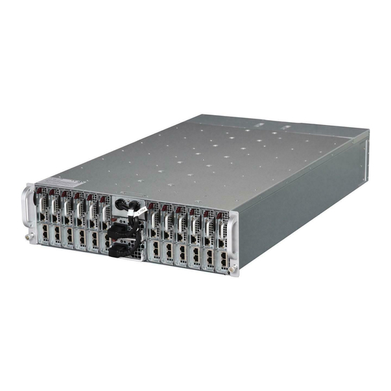
5038ML-H12TRF
USER'S MANUAL
Revision 1.0
Advertisement
Table of Contents

Related Manuals for Supero MicroCloud 5038ML-H12TRF


Summary of Contents for Supero MicroCloud 5038ML-H12TRF
- Page 1 Проконсультироваться и купить данное оборудование вы можете в компании «АНД-Системс» адрес: 125480, г.Москва, ул.Туристская, д.33/1; site: https://andpro.ru тел: +7 (495) 545-4870 email: info@andpro.ru При обращении используйте промокод AND-PDF и получите скидку. UPER ® UPER ERVER MicroCloud 5038ML-H12TRF USER’S MANUAL Revision 1.0...
- Page 2 The information in this User’s Manual has been carefully reviewed and is believed to be accurate. The vendor assumes no responsibility for any inaccuracies that may be contained in this document, makes no commitment to update or to keep current the information in this manual, or to notify any person or organization of the updates.
-
Page 3: About This Manual
Preface Preface About This Manual This manual is written for professional system integrators and PC technicians. It pro- vides information for the installation and use of the SuperServer 5038ML-H12TRF. Installation and maintenance should be performed by experienced technicians only. The SuperServer 5038ML-H12TRF is a 12-node, MicroCloud server system based on the SC939H-R1K63BP 3U chassis and 12 X10SLE-F motherboards. - Page 4 UPER ERVER 5038ML-H12TRF User's Manual Chapter 5: Advanced Motherboard Setup Chapter 5 provides detailed information on the X10SLE-F motherboard, including the locations and functions of connectors, headers and jumpers. Refer to this chap- ter when adding or removing processors or main memory and when reconfi guring the motherboard.
- Page 5 Preface Notes...
-
Page 6: Table Of Contents
UPER ERVER 5038ML-H12TRF User's Manual Table of Contents Chapter 1 Introduction Overview ......................1-1 Motherboard Features ..................1-2 Processors ...................... 1-2 Memory ......................1-2 SATA ......................1-2 Rear I/O Ports ....................1-2 IPMI ......................... 1-2 Server Chassis Features ................1-4 System Power .................... - Page 7 Table of Contents Installation Instructions ..................4-4 Circuit Breaker ....................4-5 Power Disconnection Warning ................ 4-6 Equipment Installation ..................4-8 Restricted Area ....................4-9 Battery Handling .................... 4-10 Redundant Power Supplies ................4-12 Backplane Voltage ..................4-13 Comply with Local and National Electrical Codes ........4-14 Product Disposal ...................
- Page 8 UPER ERVER 5038ML-H12TRF User's Manual Chapter 6 Advanced Chassis Setup Static-Sensitive Devices .................. 6-1 Precautions ..................... 6-1 Removing the Chassis Cover ................. 6-2 Corresponding Nodes and Fans ..............6-3 Removing and Installing Motherboard Nodes ..........6-4 Installing/Removing Hard Drives ..............6-5 System Fans ....................
-
Page 9: Chapter 1 Introduction
Chapter 1: Introduction Chapter 1 Introduction Overview The SuperServer 5038ML-H12TRF is a 12 node, MicroCloud server system com- prised of the SC939H-R1K63BP 3U chassis and 12 X10SLE-F motherboards. Please refer to our web site for information on operating systems that have been certifi... -
Page 10: Motherboard Features
UPER ERVER 5038ML-H12TRF User's Manual Motherboard Features The 5038ML-H12TRF includes a total of 12 X10SLE-F single processor mother- boards, which are based on the Intel C224 PCH chipset. Each motherboard con- stitutes a node in the system. Below are the main features of the X10SLE-F. (See Figure 1-1 for a block diagram of the chipset.) Processors Each X10SLE-F supports a single Intel®... - Page 11 Chapter 1: Introduction Figure 1-1. Intel C224 Chipset: System Block Diagram Note: This is a general block diagram. See Chapter 5 for details. Haswell DIMM1 DDR3 (CHA) (H3) DIMM2(Far) PCIe3.0_x8 1600/1333MHz PCIe x8 Micro-LP Slot 4 UDIMM 8.0Gb/s DDR3 (CHB) DIMM1 SVID 1600/1333MHz...
-
Page 12: Server Chassis Features
UPER ERVER 5038ML-H12TRF User's Manual Server Chassis Features The following is a general outline of the main features of the SC939H-R1K63BP server chassis. System Power The SC939H-R1K63BP features a redundant 1620W high-effi ciency power supply comprised of two separate power modules. This power redundancy feature allows you to replace a failed power supply without shutting down the system. -
Page 13: Contacting Supermicro
Chapter 1: Introduction Contacting Supermicro Headquarters Address: Super Micro Computer, Inc. 980 Rock Ave. San Jose, CA 95131 U.S.A. Tel: +1 (408) 503-8000 Fax: +1 (408) 503-8008 Email: marketing@supermicro.com (General Information) support@supermicro.com (Technical Support) Web Site: www.supermicro.com Europe Address: Super Micro Computer B.V. Het Sterrenbeeld 28, 5215 ML 's-Hertogenbosch, The Netherlands Tel:... - Page 14 UPER ERVER 5038ML-H12TRF User's Manual Notes...
-
Page 15: Chapter 2 Server Installation
Chapter 2: Server Installation Chapter 2 Server Installation Overview This chapter outlines the procedure to set up your system and install it to a rack. If your system is not already fully integrated with a motherboard, processors, system memory etc., please turn to the chapter or section noted in each step for details on installing specifi... -
Page 16: Warnings And Precautions
UPER ERVER 5038ML-H12TRF User's Manual • This product is not suitable for use with visual display work place devices acccording to §2 of the the German Ordinance for Work with Visual Display Units. Warnings and Precautions Rack Precautions • Ensure that the leveling jacks on the bottom of the rack are fully extended to the fl... -
Page 17: Rack Mounting Considerations
Chapter 2: Server Installation Rack Mounting Considerations Ambient Operating Temperature If installed in a closed or multi-unit rack assembly, the ambient operating tempera- ture of the rack environment may be greater than the ambient temperature of the room. Therefore, consideration should be given to installing the equipment in an environment compatible with the manufacturer’s maximum rated ambient tempera- ture (Tmra). -
Page 18: Installing The System Into A Rack
UPER ERVER 5038ML-H12TRF User's Manual Installing the System into a Rack Use the procedure below for installing the system to a rack. 1. Decide where you want to place the system into the rack (see "Rack Mount- ing Considerations" in the previous section). 2. - Page 19 Chapter 2: Server Installation Figure 2-2. Securing the Rails to the Rack Note: These handles are optional and need only be installed when mounting the system into a short rack. When mounting into a deep rack, they are unnecessary and regular screws should be used instead of thumbscrews. 6.
- Page 20 UPER ERVER 5038ML-H12TRF User's Manual Figure 2-3. Installing to the Rack Note: this fi gure is for illustrative purposes only. Always install servers to the bot- tom of a rack fi rst. Stability hazard. The rack stabilizing mechanism must be in place, or the rack must be bolted to the fl...
-
Page 21: Chapter 3 System Interface
Chapter 3: System Interface Chapter 3 System Interface Overview LEDs are included on the serverboard nodes and the power supply modules to keep you informed of their operational status. This chapter explains the meanings of all LED indicators and the appropriate response you may need to take. Motherboard Nodes Power Button/LED The main power button on each of the nodes functions as both an on/off switch and... -
Page 22: Power Supply Modules
UPER ERVER 5038ML-H12TRF User's Manual Figure 3-1. Node LED Indicator Node LED Figure 3-2. Power Supply Module LED Indicator Power Module Power Supply Modules Power Module LED Each of the power supply modules has its own LED to indicate the status of the module. -
Page 23: Chapter 4 Standardized Warning Statements For Ac Systems
Chapter 4: Warning Statements for AC Systems Chapter 4 Standardized Warning Statements for AC Systems About Standardized Warning Statements The following statements are industry standard warnings, provided to warn the user of situations which have the potential for bodily injury. Should you have questions or experience difficulty, contact Supermicro's Technical Support department for assistance. - Page 24 UPER ERVER 5038ML-H12TRF User's Manual Warnung WICHTIGE SICHERHEITSHINWEISE Dieses Warnsymbol bedeutet Gefahr. Sie befi nden sich in einer Situation, die zu Verletzungen führen kann. Machen Sie sich vor der Arbeit mit Geräten mit den Gefahren elektrischer Schaltungen und den üblichen Verfahren zur Vorbeugung vor Unfällen vertraut.
- Page 25 Warning Statements for AC Systems ﺟﺴﺪﻳﺔ ﺍﺻﺎﺑﺔ ﺗﺘﺴﺒﺐ ﻓﻲ ﺣﺎﻟﺔ ﻳﻤﻜﻦ ﺃﻥ ﺍﻧﻚ ﻓﻲ ﺧﻄﺮ ﻳﻌﻨﻲ ﻫﺬﺍ ﺍﻟﺮﻣﺰ !ﺗﺤﺬﻳﺮ ﺍﻟﺪﻭﺍﺋﺮ ﺑﺎﻟﻤﺨﺎﻁﺮ ﺍﻟﻨﺎﺟﻤﺔ ﻋﻦ ﻦ ﻋﻠﻰ ﻋﻠﻢ ، ﻛ ﻣﻌﺪﺍﺕ ﺗﻌﻤﻞ ﻋﻠﻰ ﺃﻱ ﻗﺒﻞ ﺃﻥ ﺍﻟﻜﻬﺮﺑﺎﺋﻴﺔ ﺣﻮﺍﺩﺙ ﺃﻱ ﻭﻗﻮﻉ ﻤﻨﻊ ﻟ ﺍﻟﻮﻗﺎﺋﻴﺔ...
-
Page 26: Installation Instructions
UPER ERVER 5038ML-H12TRF User's Manual Installation Instructions Warning! Read the installation instructions before connecting the system to the power source. 設置手順書 システムを電源に接続する前に、 設置手順書をお読み下さい。 警告 将此系统连接电源前,请先阅读安装说明。 警告 將系統與電源連接前,請先閱讀安裝說明。 Warnung Vor dem Anschließen des Systems an die Stromquelle die Installationsanweisungen lesen. ¡Advertencia! Lea las instrucciones de instalación antes de conectar el sistema a la red de alimentación. -
Page 27: Circuit Breaker
Chapter 4: Warning Statements for AC Systems Circuit Breaker Warning! This product relies on the building's installation for short-circuit (overcurrent) protection. Ensure that the protective device is rated not greater than: 250 V, 20 A. サーキッ ト ・ ブレーカー この製品は、 短絡 (過電流) 保護装置がある建物での設置を前提としています。 保護装置の定格が250 V、... -
Page 28: Power Disconnection Warning
UPER ERVER 5038ML-H12TRF User's Manual 경고! 이 제품은 전원의 단락(과전류)방지에 대해서 전적으로 건물의 관련 설비에 의존합니다. 보호장치의 정격이 반드시 250V(볼트), 20A(암페어)를 초과하지 않도록 해야 합니다. Waarschuwing Dit product is afhankelijk van de kortsluitbeveiliging (overspanning) van uw electrische installatie. Controleer of het beveiligde aparaat niet groter gedimensioneerd is dan 220V, 20A. - Page 29 Chapter 4: Warning Statements for AC Systems ¡Advertencia! El sistema debe ser disconnected de todas las fuentes de energía y del cable eléctrico quitado de los módulos de fuente de alimentación antes de tener acceso el interior del chasis para instalar o para quitar componentes de sistema. Attention Le système doit être débranché...
-
Page 30: Equipment Installation
UPER ERVER 5038ML-H12TRF User's Manual Equipment Installation Warning! Only trained and qualifi ed personnel should be allowed to install, replace, or service this equipment. 機器の設置 トレーニングを受け認定された人だけがこの装置の設置、 交換、 またはサービスを許可 されています。 警告 只有经过培训且具有资格的人员才能进行此设备的安装、更换和维修。 警告 只有經過受訓且具資格人員才可安裝、更換與維修此設備。 Warnung Das Installieren, Ersetzen oder Bedienen dieser Ausrüstung sollte nur geschultem, qualifi... -
Page 31: Restricted Area
Chapter 4: Warning Statements for AC Systems Waarschuwing Deze apparatuur mag alleen worden geïnstalleerd, vervangen of hersteld door geschoold en gekwalifi ceerd personeel. Restricted Area Warning! This unit is intended for installation in restricted access areas. A restricted access area can be accessed only through the use of a special tool, lock and key, or other means of security. -
Page 32: Battery Handling
UPER ERVER 5038ML-H12TRF User's Manual אזור עם גישה מוגבלת !אזהרה יש להתקין את היחידה באזורים שיש בהם הגבלת גישה. הגישה ניתנת בעזרת .('כלי אבטחה בלבד )מפתח, מנעול וכד ﻣﺤﻈﻮﺭﺓ ﻣﻨﺎﻁﻖ ﻟﺘﺮﻛﻴﺒﻬﺎ ﻓﻲ ﻫﺬﻩ ﺍﻟﻮﺣﺪﺓ ﺗﺨﺼﻴﺺ ﺗﻢ ،ﺃﺩﺍﺓ ﺧﺎﺻﺔ ﻣﻦ ﺧﻼﻝ ﺍﺳﺘﺨﺪﺍﻡ ﻓﻘﻂ... - Page 33 Chapter 4: Warning Statements for AC Systems Warnung Bei Einsetzen einer falschen Batterie besteht Explosionsgefahr. Ersetzen Sie die Batterie nur durch den gleichen oder vom Hersteller empfohlenen Batterietyp. Entsorgen Sie die benutzten Batterien nach den Anweisungen des Herstellers. Attention Danger d'explosion si la pile n'est pas remplacée correctement. Ne la remplacer que par une pile de type semblable ou équivalent, recommandée par le fabricant.
-
Page 34: Redundant Power Supplies
UPER ERVER 5038ML-H12TRF User's Manual Redundant Power Supplies Warning! This unit might have more than one power supply connection. All connections must be removed to de-energize the unit. 冗長電源装置 このユニッ トは複数の電源装置が接続されている場合があります。 ユニッ トの電源を切るためには、 すべての接続を取り外さなければなりません。 警告 此部件连接的电源可能不止一个,必须将所有电源断开才能停止给该部件供电。 警告 此裝置連接的電源可能不只一個,必須切斷所有電源才能停止對該裝置的供電。 Warnung Dieses Gerät kann mehr als eine Stromzufuhr haben. Um sicherzustellen, dass der Einheit kein trom zugeführt wird, müssen alle Verbindungen entfernt werden. -
Page 35: Backplane Voltage
Chapter 4: Warning Statements for AC Systems ﺍﻣﺪﺍﺩ ﺍﻟﻄﺎﻗﺔ ﺑﻮﺣﺪﺍﺕ ﻋﺪﺓ ﺍﺗﺼﺎﻻﺕ ﺠﻬﺎﺯ ﺍﻟ ﻳﻜﻮﻥ ﻟﻬﺬﺍ ﻗﺪ ﺍﻟﻜﻬﺮﺑﺎء ﻋﻦ ﻮﺣﺪﺓ ﺍﻟ ﻟﻌﺰﻝ ﻛﺎﻓﺔ ﺍﻻﺗﺼﺎﻻﺕ ﻳﺠﺐ ﺇﺯﺍﻟﺔ 경고! 이 장치에는 한 개 이상의 전원 공급 단자가 연결되어 있을 수 있습니다. 이 장치에 전원을... -
Page 36: Comply With Local And National Electrical Codes
UPER ERVER 5038ML-H12TRF User's Manual מתח בפנל האחורי !הרה אז קיימת סכנת מתח בפנל האחורי בזמן תפעול המערכת. יש להיזהר במהלך .העבודה ﺍﻟﻠﻮﺣﺔ ﺃﻭﺍﻟﻄﺎﻗﺔ ﺍﻟﻤﻮﺟﻮﺩﺓ ﻋﻠﻰ ﺍﻟﺘﻴﺎﺭ ﺍﻟﻜﻬﺮﺑﺎﺋﻲ ﻣﻦ ﺧﻄﺮ ﻫﻨﺎﻙ ﻫﺬﺍ ﺍﻟﺠﻬﺎﺯ ﺧﺪﻣﺔ ﻛﻦ ﺣﺬﺭﺍ ﻋﻨﺪ ﻳﻌﻤﻞ ﺍﻟﻨﻈﺎﻡ ﻋﻨﺪﻣﺎ ﻳﻜﻮﻥ 경고! 시스템이... -
Page 37: Product Disposal
Chapter 4: Warning Statements for AC Systems Attention L'équipement doit être installé conformément aux normes électriques nationales et locales. תיאום חוקי החשמל הארצי !אזהרה הציוד חייבת להיות תואמת לחוקי החשמל המקומיים והארציים התקנת ﺍﻟﻤﺘﻌﻠﻘﺔ ﺍﻟﻤﺤﻠﻴﺔ ﻭﺍﻟﻮﻁﻨﻴﺔ ﻘﻮﺍﻧﻴﻦ ﻳﺠﺐ ﺃﻥ ﻳﻤﺘﺜﻞ ﻟﻠ ﺍﻟﻜﻬﺮﺑﺎﺋﻴﺔ... -
Page 38: Hot Swap Fan Warning
UPER ERVER 5038ML-H12TRF User's Manual ¡Advertencia! Al deshacerse por completo de este producto debe seguir todas las leyes y reglamentos nacionales. Attention La mise au rebut ou le recyclage de ce produit sont généralement soumis à des lois et/ou directives de respect de l'environnement. Renseignez-vous auprès de l'organisme compétent. - Page 39 Chapter 4: Warning Statements for AC Systems 警告 當您從機架移除風扇裝置,風扇可能仍在轉動。小心不要將手指、螺絲起子和其他 物品太靠近風扇。 Warnung Die Lüfter drehen sich u. U. noch, wenn die Lüfterbaugruppe aus dem Chassis genommen wird. Halten Sie Finger, Schraubendreher und andere Gegenstände von den Öffnungen des Lüftergehäuses entfernt. ¡Advertencia! Los ventiladores podran dar vuelta cuando usted quite ell montaje del ventilador del chasis.
-
Page 40: Power Cable And Ac Adapter
UPER ERVER 5038ML-H12TRF User's Manual Power Cable and AC Adapter Warning! When installing the product, use the provided or designated connection cables, power cables and AC adaptors. Using any other cables and adaptors could cause a malfunction or a fi re. Electrical Appliance and Material Safety Law prohibits the use of UL or CSA -certifi... - Page 41 Chapter 4: Warning Statements for AC Systems Attention Lors de l'installation du produit, utilisez les bables de connection fournis ou désigné. L'utilisation d'autres cables et adaptateurs peut provoquer un dysfonctionnement ou un incendie. Appareils électroménagers et de loi sur la sécurité Matériel interdit l'utilisation de UL ou CSA câbles certifi...
- Page 42 UPER ERVER 5038ML-H12TRF User's Manual Notes 4-20...
-
Page 43: Chapter 5 Advanced Motherboard Setup
Chapter 5: Advanced Motherboard Setup Chapter 5 Advanced Motherboard Setup This chapter covers the steps required to connect the data and power cables and install add-on cards. All motherboard jumpers and connections are also described. A layout and quick reference chart are included in this chapter for your reference. Remember to completely close the chassis when you have fi... -
Page 44: Motherboard Installation/Removal
UPER ERVER 5038ML-H12TRF User's Manual Motherboard Installation/Removal The X10SLE-F motherboards have been preinstalled into carriers to simplify install- ing and removing the nodes from the SC939H-R1K63BP chassis. The motherboards should remain in these carriers at all times. If a failed node needs to be returned for repair or replacement, the motherboard is to be shipped assembled in its car- rier and not by itself. -
Page 45: I/O Ports
Chapter 5: Advanced Motherboard Setup I/O Ports The I/O ports are located at the back of the motherbord node. See Figure 5-1 below for the colors and locations of the various I/O ports. See Section 5-10 for port defi nitions. Figure 5-1. -
Page 46: Processor And Heatsink Installation
UPER ERVER 5038ML-H12TRF User's Manual Processor and Heatsink Installation Warning: Avoid placing direct pressure to the top of the processor. Notes: • Always connect the power cord last and always remove it before adding, re- moving or changing any hardware components. Make sure that you install the processor into the CPU socket before you install the CPU heatsink. - Page 47 Chapter 5: Advanced Motherboard Setup 3. Once the load plate is open, use your thumb and your index fi nger to hold the CPU at the north center edge and the south center edge of the CPU. North Center Edge South Center Edge 4.
- Page 48 UPER ERVER 5038ML-H12TRF User's Manual 7. Once the CPU is properly installed, use your thumb to gently push the load plat handle down to the handle lock and lock it. CPU properly installed Load Plate Handle is locked into place 8.
-
Page 49: Installing A Heatsink
Chapter 5: Advanced Motherboard Setup Installing a Heatsink 1. With the node removed, remove the air shroud. 2. Do not apply any thermal grease to the heatsink or the CPU die; the required amount has already been applied. 3. Place the heatsink on top of the CPU so that the four mounting holes are aligned with those on the motherboard and the heatsink bracket underneath. -
Page 50: Installing Memory
UPER ERVER 5038ML-H12TRF User's Manual Installing Memory Caution: Exercise extreme care when installing or removing DIMM modules to prevent any possible damage to the DIMMs or their sockets How to Install Memory 1. Insert the desired number of DIMMs into the memory slots in the following order: DIMMA2, then DIMMB2, DIMMA1, DIMMB1. -
Page 51: Memory Population Guidelines
Chapter 5: Advanced Motherboard Setup Figure 5-3. Populating DIMM Slots Towards the CPU Channel A, Slot 1 Channel A, Slot 2 (Blue Slot) Channel B, Slot 1 Channel B, Slot 2 (Blue Slot) Towards the edge of the motherboard Memory Population Guidelines 1. -
Page 52: Microlp Expansion Module
UPER ERVER 5038ML-H12TRF User's Manual MicroLP Expansion Module Each of the 12 nodes in the 5038ML-H12TRF has one MicroLP slot, which can support a single MicroLP expansion module. Follow the instructions below to install this module. Installing a MicroLP Expansion Module 1. - Page 53 Chapter 5: Advanced Motherboard Setup Expansion Card Riser Card Bracket Figure 5-4. Installing the MicroLP Expansion Module Notes: The node and motherboard shown above are examples. Your actual node and motherboard may vary from those illustrated. The fi gure above shows an exploded view of the module. The expansion card, riser card and mounting bracket come pre-assembled.
-
Page 54: Motherboard Details
UPER ERVER 5038ML-H12TRF User's Manual Motherboard Details Figure 5-5. X10SLE-F Layout JKVM1 LED5 JPG1 IPMI_LAN AST2400 Battery BIOS JPME2 Intel LP C226/C224 JBT1 JPME1 MAC CODE X10SLE-F/HF Rev. 1.00 JP16 JPWR2 JP17 JP18 JPV1 5-12... -
Page 55: X10Sle-F Quick Reference
Chapter 5: Advanced Motherboard Setup X10SLE-F Quick Reference Jumper Description Default Setting JBT1 CMOS Clear (See Section 5-10) JPG1 VGA Enable/Disable Pins 1-2 (Enabled) JPME1 ME Recovery Pins 1-2 (Normal) JPME2 Manufacture Mode Select Pins 1-2 (Normal) JWD1 Watch Dog Pins 1-2 (NMI) Connector Description... -
Page 56: Connector Defi Nitions
UPER ERVER 5038ML-H12TRF User's Manual Connector Defi nitions Unit Identifi er Switch/UID LED Indicators A Unit Identifier (UID) button and a LED indicator are located on the moth- UID Switch erboard. The UID button is located at Pin# Defi nition JUIDB1, and LED is located at LED6 on Ground the backplane. - Page 57 Chapter 5: Advanced Motherboard Setup SMC-Proprietary Power This motherboard supports SMC-Proprietary power supply. Be sure to use the power supply recommended by Supermicro and connect it to JPWR2 to provide power to your system. Power Output for HDD An HDD power out connector is located at JP16. Connect a power cable to JP16 to provide 12V or 5 V power to the devices installed in hard drive disks.
- Page 58 UPER ERVER 5038ML-H12TRF User's Manual USB (x2)/VGA/COM Connector JKVM1 supports USB(x2)/VGA/COM (UART) connections on the I/O back- plane to provide console redirection support or remote networking interface. TPM/Port 80 Header Pin Defi nitions Pin # Defi nition Pin # Defi nition TPM Header/Port 80 Header LCLK A Trusted Platform Module/Port 80 head-...
-
Page 59: 5-10 Jumper Settings
Chapter 5: Advanced Motherboard Setup 5-10 Jumper Settings Explanation of Jumpers To modify the operation of the mother- board, jumpers can be used to choose Connector between optional settings. Jumpers Pins create shorts between two pins to change the function of the connector. Pin 1 is identifi... - Page 60 UPER ERVER 5038ML-H12TRF User's Manual VGA Enable/Disable (JPG1) VGA Enable/Disable Jumper Settings JPG1 allows the user to enable the Jumper Setting Defi nition onboard VGA connector (through the Pins 1-2 Enabled KVM). Close pins 1~2 to enable the Pins 2-3 Disabled VGA.
-
Page 61: 5-11 Onboard Indicators
Chapter 5: Advanced Motherboard Setup 5-11 Onboard Indicators Activity LED Link LED IPMI IPMI Dedicated LAN Port A dedicated IPMI LAN port is located IPMI LAN Link Speed LED on the I/O backpanel. The yellow LED Linl LED Color/State Defi nition on the right indicates activity, while the Green 100 Mbps... -
Page 62: 5-13 Installing Software
UPER ERVER 5038ML-H12TRF User's Manual 5-13 Installing Software The Supermicro ftp site contains drivers and utilities for your system at ftp://ftp. supermicro.com. Some of these must be installed, such as the chipset driver. After accessing the ftp site, go into the CDR_Images directory and locate the ISO fi... -
Page 63: Superdoctor Iii
Chapter 5: Advanced Motherboard Setup SuperDoctor III The SuperDoctor® III program is a web-based management tool that supports remote management capability. It includes Remote and Local Management tools. The local management is called SD III Client. The SuperDoctor III program allows you to monitor the environment and operations of your system. - Page 64 UPER ERVER 5038ML-H12TRF User's Manual Figure 5-8. SuperDoctor III Interface Display Screen (Remote Control) Note: The SuperDoctor III program and User’s Manual can be downloaded from the Supermicro web site at http://www.supermicro.com/products/accessories/soft- ware/SuperDoctorIII.cfm. For Linux, we recommend that you use the SuperDoctor II application instead.
-
Page 65: 5-14 Onboard Battery
Chapter 5: Advanced Motherboard Setup 5-14 Onboard Battery Please handle used batteries carefully. Do not damage the battery in any way; a damaged battery may release hazardous materials into the environment. Do not discard a used battery in the garbage or a public landfi ll. Please comply with the regulations set up by your local hazardous waste management agency to dispose of your used battery properly. -
Page 66: Chapter 6 Advanced Chassis Setup
Chapter 6: Advanced Chassis Setup Chapter 6 Advanced Chassis Setup This chapter covers the steps required to install components and perform main- tenance on the SC939H-R1K63BP chassis. For component installation, follow the steps in the order given to eliminate the most common problems encountered. If some steps are unnecessary, skip ahead to the step that follows. -
Page 67: Removing The Chassis Cover
UPER ERVER 5038ML-H12TRF User's Manual Removing the Chassis Cover Figure 6-1. Removing the Chassis Cover Removing the Chassis Cover 1. Disconnect the chassis from any power source. 2. Remove the three screws which secure the top cover to the chassis as il- lustrated above. -
Page 68: Corresponding Nodes And Fans
Chapter 6: Advanced Chassis Setup Corresponding Nodes and Fans The 5038ML-H12TRF contains 12 individual motherboards contained in separate nodes. Three nodes each share a common fan (see fi gure below). Figure 6-2. Corresponding Nodes and Fans Cooling Zone 1 Fan 1 Fan 2 Fan 3 Fan 4... -
Page 69: Removing And Installing Motherboard Nodes
UPER ERVER 5038ML-H12TRF User's Manual Removing and Installing Motherboard Nodes Release Tab Handle Figure 6-3. Removing/Installing a Node The system comes features twelve removable nodes. Each node contains an in- dividual motherboard and hard drives mounted on a sled, which allows it to easily be installed and removed from the chassis. -
Page 70: Installing/Removing Hard Drives
Chapter 6: Advanced Chassis Setup Installing/Removing Hard Drives The hard drives are installed directly to the sled, which must fi rst be removed from the system. For this reason, hard drives are not hot-swappable. Either two 3.5" or four 2.5" hard drives can be installed in each sled (node). An optional kit is required to install 2.5"... - Page 71 UPER ERVER 5038ML-H12TRF User's Manual Figure 6-5. Installing/Removing 2.5" Hard Drives (Optional) Note: Enterprise level hard disk drives are recommended for use in Supermicro chassis and servers. For information on recommended HDDs, visit the Supermicro Web site at http://www.supermicro.com/products/nfo/storage.cfm...
-
Page 72: System Fans
Chapter 6: Advanced Chassis Setup System Fans Four 9-cm fans circulate air through the chassis to lower the internal temperature. These fans are designed to be easily changed, with no tools required and no need to remove any other parts inside the chassis. In the event of a fan failure, follow the instructions below to replace it. -
Page 73: Power Supply
UPER ERVER 5038ML-H12TRF User's Manual Power Supply The system includes a redundant 1620 watt, high-effi ciency power supply. The two power supply modules are auto-switching capable, which enables them to automatically sense and operate at a 100V to 240V input voltage. An amber light is illuminated on the power supply when the power is off. -
Page 74: Chapter 7 Bios
Chapter 7: BIOS Chapter 7 BIOS Introduction This chapter describes the AMI BIOS Setup Utility for the X10SLE-F/X10SLE-HF. The ROM BIOS is stored in a Flash EEPROM and can be easily updated. This chapter describes the basic navigation of the AMI BIOS Setup Utility setup screens. Note: For AMI BIOS Recovery, please refer to the UEFI BIOS Recovery Instructions in Appendix C. -
Page 75: How To Start The Setup Utility
UPER ERVER 5038ML-H12TRF User's Manual How to Start the Setup Utility Normally, the only visible Power-On Self-Test (POST) routine is the memory test. As the memory is being tested, press the <Delete> key to enter the main menu of the AMI BIOS Setup Utility. From the main menu, you can access the other setup screens. - Page 76 Chapter 7: BIOS System Date/System Time Use this option to change the system date and time. Highlight System Date or System Time using the arrow keys. Enter new values through the keyboard. Press the <Tab> key or the arrow keys to move between fi elds. The date must be entered in Day MM/DD/YY format.
-
Page 77: Advanced Setup Confi Gurations
UPER ERVER 5038ML-H12TRF User's Manual Advanced Setup Confi gurations Use the arrow keys to select Boot Setup and press <Enter> to access the submenu items: Warning: Take Caution when changing the Advanced settings. An incorrect value, a very high DRAM frequency, or an incorrect DRAM timing setting may make the system unstable. - Page 78 Chapter 7: BIOS Wait For 'F1' If Error Select Enabled to force the system to wait until the 'F1' key is pressed if an error occurs. The options are Disabled and Enabled. Interrupt 19 Capture Interrupt 19 is the software interrupt that handles the boot disk function. When this item is set to Enabled, the ROM BIOS of the host adaptors will "capture"...
- Page 79 UPER ERVER 5038ML-H12TRF User's Manual • CPU Signature • CPU Stepping • Microcode Patch • FSB Speed • Maximum CPU Speed • Minimum CPU Speed • CPU Speed • Processor Cores • Intel HT(Hyper-Threading) Technology • Intel VT-x (Virtualization) Technology •...
- Page 80 Chapter 7: BIOS Active Processor Cores This feature determines how many CPU cores will be activated for each CPU. When all is selected, all cores in the CPU will be activated. (Please refer to Intel's web site for more information.) The options are All, 1, 2, and 3. Limit CPUID Maximum Select Enabled to set the maximum CPU ID value and to boot the legacy operat- ing systems that cannot support processors with extended CPUID functions.
- Page 81 UPER ERVER 5038ML-H12TRF User's Manual Boot Performance Mode Use this item to set the performance mode for the CPU upon bootup. Select Max Non-Turbo to achieve the maximal performance without invoking out-of-band or turbo mode for the CPU. The options are Max Non-Turbo Performance and Turbo Performance.
- Page 82 Chapter 7: BIOS CPU Power Limit3 Time (Available when "Turbo Mode" is set to Enabled) Use this feature to set the length of time value for CPU Power Limit3 for your system. Use the number keys on your keyboard to enter the value. Enter 0 to use the manufacture default setting.
- Page 83 UPER ERVER 5038ML-H12TRF User's Manual Energy Performance Use this feature to select an appropriate fan setting to achieve the maximum system performance (with maximum cooling) or to achieve maximum energy effi ciency (with maximum power saving). The fan speeds are controlled by the fi rmware manage- ment via IPMI 2.0.
- Page 84 Chapter 7: BIOS C7 Latency (Available when "CPU C-States" is set to Enabled) Select Short to set a short delay time(period) during which the BIOS reports CPU C7 State (ACPI C3) to the operating system. Select Long to set a long delay time(period) during which the BIOS reports CPU C7 State (ACPI C3) to the operating system.
- Page 85 UPER ERVER 5038ML-H12TRF User's Manual VT-d Select Enabled to enable Intel Virtualization Technology support for Direct I/O VT-d by reporting the I/O device assignments to VMM through the DMAR ACPI Tables. This feature offers fully-protected I/O resource-sharing across the Intel platforms, providing the user with greater reliability, security and availability in networking and data-sharing.
- Page 86 Chapter 7: BIOS DMI Link ASPM Control This feature confi gures the ASPM (Active State Power Management) settings for the devices/components connected to the DMI Link on the System Agent side. The options are Disabled, L0s, L1, and L0sL1. PCH Link ASPM Control Select Enabled to support ASPM (Active State Power Management) for both North Bridge and South Bridge.
- Page 87 UPER ERVER 5038ML-H12TRF User's Manual Max TOLUD (Top of Low Usable DRAM) This feature sets the maximum TOLUD value, which specifi es the "Top of Low Usable DRAM" memory space to be used by internal graphics devices or graph- ics controllers, if these devices are enabled. The options are Dynamic, 1 GB, 1.25 GB, 1.5 GB, 1.75 GB, 2 GB, 2.25 GB, 2.5 GB, 2.75 GB, 3 GB and 3.25 GB.
- Page 88 Chapter 7: BIOS change should be claimed by the XHCI driver. The settings are Enabled and Disabled. EHCI Hand-Off This item is for Operating Systems that do not support Enhanced Host Controller Interface (EHCI) hand-off. When this item is enabled, EHCI ownership change will be claimed by the EHCI driver.
- Page 89 UPER ERVER 5038ML-H12TRF User's Manual Port 0 ~ Port 1 SATA Device Type This feature confi gures the selected SATA port to support either a solid state drive or hard disk drive. The options are Hard Disk Drive and Solid Sate Drive. Port 0 ~ Port 4 Spin Up Device On an edge detect from 0 to 1, set this item to allow the PCH to start a COMRE- SET initialization sequence to the device.
-
Page 90: Acpi Settings
Chapter 7: BIOS Above 4G Decoding Select Enabled for 64-bit devices to be decoded above the 4GB address space if 64bit PCI decoding is supported by the system. The options are Disabled and Enabled. VGA Palette Snoop Select Enabled to support VGA palette register snooping which will allow a PCI card that does not contain its own VGA color palette to examine the video card pal- ette and mimic it for proper color display. - Page 91 UPER ERVER 5038ML-H12TRF User's Manual synchronizing multimedia streams, providing smooth playback and reducing the de- pendency on other timestamp calculation devices, such as an x86 RDTSC Instruc- tion embedded in the CPU. The High Performance Event Timer is used to replace the 8254 Programmable Interval Timer.
- Page 92 Chapter 7: BIOS TPM State Select Enabled to use TPM (Trusted Platform Module) settings for system data security. The options are Disabled and Enabled. Note: The system will reboot for the change on TPM State to take effect. Pending Operation Use this item to schedule a TPM-related operation to be performed by a security device for TPM support.
-
Page 93: Serial Port Console Redirection
UPER ERVER 5038ML-H12TRF User's Manual Serial Port Console Redirection COM1/SOL Use this feature to enable console redirection support for COM1 and SOL ports. The options are Enabled and Disabled. The default setting for COM1 is Disabled. The default setting for SOL is Enabled. Console Redirection Settings This feature allows the user to specify how the host computer will interface with the client computer on a remote site. - Page 94 Chapter 7: BIOS Flow Control Use this feature to set the fl ow control for Console Redirection to prevent data loss caused by buffer overfl ow. Send a "Stop" signal to stop sending data when the receiving buffer is full. Send a "Start" signal to start sending data when the receiving buffer is empty.
- Page 95 UPER ERVER 5038ML-H12TRF User's Manual Console Redirection Settings (for EMS) This feature allows the user to specify how the host computer will exchange data with the client computer, which is the remote computer used by the user. Out-of-Band Management Port The feature selects a serial port used by the Microsoft Windows Emergency Management Services (EMS) to communicate with a remote server.
-
Page 96: Event Logs
Chapter 7: BIOS Event Logs Change SMBIOS Event Log Settings Enabling/Disabling Options SMBIOS Event Log Change this item to enable or disable all features of the SMBIOS Event Logging during system boot. The options are Enabled and Disabled. Erasing Settings Erase Event Log If No is selected, data stored in the event log will not be erased. -
Page 97: Ipmi
UPER ERVER 5038ML-H12TRF User's Manual MECI The Multiple-Event-Count Increment (MECI) counter counts the number of oc- curences. A duplicate event must happen before the MECI counter is incremented. This is a numeric value. The default value is 1. METW Use the Multiple-Event-Time Window (METW) to defi ne the length of time (in minute) it must pass before a duplicate log-event entry is generated. -
Page 98: System Event Log
Chapter 7: BIOS IPMI Firmware Revision This item indicates the IPMI fi rmware revision used in your system. IPMI Status This item indicates the status of the IPMI fi rmware installed in your system. System Event Log Enabling/Disabling Options SEL Components Select Enabled for all system event logging at bootup. - Page 99 UPER ERVER 5038ML-H12TRF User's Manual Confi guration Address Source This feature allows the user to select the source of the IP address for this computer. If Static is selected, you will need to know the IP address of this computer and enter it to the system manually in the fi...
-
Page 100: Boot Settings
Chapter 7: BIOS Boot Settings Use this feature to confi gure Boot Settings: Set Boot Priority This option prioritizes the order of bootable devices that the system to boot from. Press [ENTER] on each entry from top to bottom to select devices. •... - Page 101 UPER ERVER 5038ML-H12TRF User's Manual UEFI Boot Drive BBS Priorities • 1st Boot Device Add New Boot Option This feature allows the user to add a boot device from which the systems will boot after power-on. Add Boot Option Enter the name of the new boot option here.
-
Page 102: Security Settings
Chapter 7: BIOS Security Settings This menu allows the user to confi gure the following security settings for the system. Administrator Password Use this feature to set the Administrator Password which is required to enter the BIOS setup utility. The length of the password should be from 3 characters to 8 characters long. -
Page 103: Save & Exit
UPER ERVER 5038ML-H12TRF User's Manual Save & Exit Select the Exit tab from the BIOS Setup Utility screen to enter the Exit BIOS Setup screen. Discard Changes and Exit Select this option to exit the BIOS Setup without making any permanent changes to the system confi... - Page 104 Chapter 7: BIOS Restore Optimized Defaults To set this feature, select Restore Defaults from the Exit menu and press <Enter>. These are factory settings designed for maximum system stability, but not for maximum performance. Save As User Defaults To set this feature, select Save as User Defaults from the Exit menu and press <En- ter>.
- Page 105 UPER ERVER 5038ML-H12TRF User's Manual Notes 7-32...
-
Page 106: Appendix A Bios Error Beep Codes
Appendix A: BIOS Error Beep Codes Appendix A BIOS Error Beep Codes During the POST (Power-On Self-Test) routines, which are performed each time the system is powered on, errors may occur. Non-fatal errors are those which, in most cases, allow the system to continue with bootup. - Page 107 UPER ERVER 5038ML-H12TRF User's Manual Notes...
-
Page 108: Appendix B System Specifi Cations
Appendix B: System Specifi cations Appendix B System Specifi cations Processors Each node supports a single Intel® Xeon® E3-1200 v3 processor (up to 80W) or 4th Gen Core i3, Pentium®, Celeron® processor in an LGA 1150 socket (Socket Note: Please refer to our web site for a complete listing of supported processors. Chipset Intel C224 PCH BIOS... - Page 109 UPER ERVER 5038ML-H12TRF User's Manual Dimensions: (WxHxD) 17.5 x 5.21 x 29.5 in. (444.5 x 132 x 749.3 mm) Weight Barebone: 95 lbs. (43.2 kg) System Cooling Four 9-cm system fans System Input Requirements AC Input Voltage: 100 - 240V AC auto-range Rated Input Current: 11.5 - 5.5A max Rated Input Frequency: 50 to 60 Hz Power Supply...
- Page 110 Appendix B: System Specifi cations Non-operating Relative Humidity: 5 to 95% (non-condensing) Regulatory Compliance Electromagnetic Emissions: FCC Class A, EN 55022 Class A, EN 61000-3-2/-3-3, CISPR 22 Class A Electromagnetic Immunity: EN 55024/CISPR 24, (EN 61000-4-2, EN 61000-4-3, EN 61000-4-4, EN 61000- 4-5, EN 61000-4-6, EN 61000-4-8, EN 61000-4-11) Safety: EN 60950/IEC 60950-Compliant...
- Page 111 UPER ERVER 5038ML-H12TRF User's Manual (continued from front) The products sold by Supermicro are not intended for and will not be used in life support systems, medical equipment, nuclear facilities or systems, aircraft, aircraft devices, aircraft/emergency com- munication devices or other critical systems whose failure to perform be reasonably expected to result in signifi...
Need help?
Do you have a question about the MicroCloud 5038ML-H12TRF and is the answer not in the manual?
Questions and answers