
Subscribe to Our Youtube Channel
Related Manuals for Supero 5037MR


Summary of Contents for Supero 5037MR
- Page 1 UPER ® UPER ERVER Super Microcloud 5037MR-H8TRF USER’S MANUAL Revision 1.0...
- Page 2 The information in this User’s Manual has been carefully reviewed and is believed to be accurate. The vendor assumes no responsibility for any inaccuracies that may be contained in this document, makes no commitment to update or to keep current the information in this manual, or to notify any person or organization of the updates.
-
Page 3: About This Manual
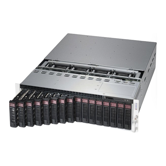
About This Manual This manual is written for professional system integrators and PC technicians. It provides information for the installation and use of the SuperServer 5037MR-H8TRF. Installation and maintenance should be performed by experienced technicians only. The SuperServer 5037MR-H8TRF is an 8-node, Microcloud server system based on the SC938BH-R1K62B 3U chassis and eight X9SRD-F motherboards. - Page 4 UPER ERVER 5037MR-H8TRF User's Manual Chapter 5: Advanced Motherboard Setup Chapter 5 provides detailed information on the X9SRD-F motherboard, including the locations and functions of connectors, headers and jumpers. Refer to this chapter when adding or removing processors or main memory and when reconfi guring the motherboard.
- Page 5 Preface Notes...
-
Page 6: Table Of Contents
UPER ERVER 5037MR-H8TRF User's Manual Table of Contents Chapter 1 Introduction Overview ......................1-1 Motherboard Features ..................1-2 Processors ...................... 1-2 Memory ......................1-2 SATA ......................1-2 Rear I/O Ports ....................1-2 Graphics ......................1-2 IPMI ......................... 1-3 Other Features ....................1-3 Server Chassis Features ................ - Page 7 Table of Contents Checking the Motherboard Setup ..............2-10 Preparing to Power On ................. 2-12 Chapter 3 System Interface Overview ......................3-1 Control Panel Buttons ..................3-1 Power Button/LED ................... 3-1 LEDs ........................ 3-2 Power Failure LED ..................3-2 Hard Drive Carrier LEDs ................. 3-3 Node LEDs ......................
- Page 8 UPER ERVER 5037MR-H8TRF User's Manual 5-11 Jumper Settings .................... 5-15 5-12 Onboard Indicators ..................5-18 5-13 SATA Drive Connections ................5-19 5-14 Installing Software ..................5-19 Supero Doctor III ................... 5-20 Chapter 6 Advanced Chassis Setup Static-Sensitive Devices .................. 6-1 Precautions .....................
-
Page 9: Chapter 1 Introduction
SC938BH-R1K62B 3U chassis and eight X9SRD-F motherboards. Please refer to our web site for information on operating systems that have been certifi ed for use with the 5037MR-H8TRF (www.supermicro. com). In addition to the motherboard and chassis, various hardware components have been included with the 5037MR-H8TRF, as listed below: •... -
Page 10: Motherboard Features
ERVER 5037MR-H8TRF User's Manual Motherboard Features The 5037MR-H8TRF includes a total of eight X9SRD-F single processor moth- erboards, which are based on the Intel C602J PCH chipset. Below are the main features of the X9SRD-F. (See Figure 1-1 for a block diagram of the chipset). -
Page 11: Ipmi
Chapter 1: Introduction IPMI IPMI (Intelligent Platform Management Interface) is a hardware-level interface speci- fi cation that provides remote access, monitoring and administration for Supermicro server platforms. IPMI allows server administrators to view a server’s hardware status remotely, receive an alarm automatically if a failure occurs, and power cycle a system that is non-responsive. -
Page 12: Server Chassis Features
Front Control Panel The control panel on the 5037MR-H8TRF features a power button/LED, a power fail LED and eight LEDs to indicate the status of each node in the system. Cooling System The SC938BH-R1K62B chassis includes four 8-cm fans located behind the back- plane. -
Page 13: Contacting Supermicro
Chapter 1: Introduction Contacting Supermicro Headquarters Address: Super Micro Computer, Inc. 980 Rock Ave. San Jose, CA 95131 U.S.A. Tel: +1 (408) 503-8000 Fax: +1 (408) 503-8008 Email: marketing@supermicro.com (General Information) support@supermicro.com (Technical Support) Web Site: www.supermicro.com Europe Address: Super Micro Computer B.V. Het Sterrenbeeld 28, 5215 ML 's-Hertogenbosch, The Netherlands Tel:... - Page 14 UPER ERVER 5037MR-H8TRF User's Manual Notes...
-
Page 15: Chapter 2 Server Installation
Unpacking the System You should inspect the box the 5037MR-H8TRF was shipped in and note if it was damaged in any way. If the server itself shows damage you should fi le a damage claim with the carrier who delivered it. -
Page 16: Choosing A Setup Location
UPER ERVER 5037MR-H8TRF User's Manual Choosing a Setup Location • Leave enough clearance in front of the rack to enable you to open the front door completely (~25 inches) and approximately 30 inches of clearance in the back of the rack to allow for suffi cient airfl ow and ease in servicing. -
Page 17: Rack Mounting Considerations
Chapter 2: Server Installation • Allow the hot plug SATA drives and power supply modules to cool before touch- ing them. • Always keep the rack's front door and all panels and components on the servers closed when not servicing to maintain proper cooling. Rack Mounting Considerations Ambient Operating Temperature If installed in a closed or multi-unit rack assembly, the ambient operating tempera-... -
Page 18: Installing The System Into A Rack
UPER ERVER 5037MR-H8TRF User's Manual Installing the System into a Rack This section provides information on installing the chassis into a rack unit with the rails provided. There are a variety of rack units on the market, which may mean that the assembly procedure will differ slightly from the instructions provided. -
Page 19: Locking Tabs
Chapter 2: Server Installation Locking Tabs Each inner rail has a locking tab. This tab locks the chassis into place when installed and pushed fully into the rack. These tabs also lock the chassis in place when fully extended from the rack. This prevents the server from coming completely out of the rack when when the chassis is pulled out for servicing. -
Page 20: Installing The Inner Rails On The Chassis
UPER ERVER 5037MR-H8TRF User's Manual Inner Rails Figure 2-3. Installing the Inner Rails Figure 2-4. Inner Rails Installed on the Chassis Installing The Inner Rails on the Chassis Installing the Inner Rails 1. Confi rm that the left and right inner rails have been correctly identifi ed. -
Page 21: Installing The Outer Rails On The Rack
Chapter 2: Server Installation Figure 2-5. Extending and Releasing the Outer Rails Installing the Outer Rails on the Rack Installing the Outer Rails 1. Press upward on the locking tab at the rear end of the middle rail. 2. Push the middle rail back into the outer rail. 3. -
Page 22: Standard Chassis Installation
UPER ERVER 5037MR-H8TRF User's Manual Ball-Bearing Shuttle Figure 2-6. Installing the Chassis into a Rack Standard Chassis Installation 1. Confi rm that the inner rails are properly installed on the chassis. 2. Confi rm that the outer rails are correctly installed on the rack. -
Page 23: Optional Quick Installation Method
Chapter 2: Server Installation Optional Quick Installation Method The following quick installation method may be used to install the chassis onto a rack. 1. Install the inner rails on the chassis as previously described on page 2-6. 2. Install the whole rail assembly onto the rack as described on page 2-7. 3. -
Page 24: Checking The Motherboard Setup
UPER ERVER 5037MR-H8TRF User's Manual Checking the Motherboard Setup After setting up the the system, you may need to open the unit to make sure all the connections have been made. Note: Before operating the system for the fi rst time, it is important to remove the protective fi... - Page 25 Chapter 2: Server Installation Figure 2-8. Accessing the Inside of the System Remove Three Screws Remove Film From Vents Warning: Except for short periods of time, do NOT operate the server without the cover in place. The chassis cover must be in place to allow proper airfl...
-
Page 26: Preparing To Power On
UPER ERVER 5037MR-H8TRF User's Manual Preparing to Power On Checking the Drives 1. Depending upon your system's confi guration, your system may have hard drives already installed. If you need to install hard drives, please refer to Chapter 6. Checking the Airfl ow 1. -
Page 27: Chapter 3 System Interface
Chapter 3: System Interface Chapter 3 System Interface Overview LEDs are included on the control panel, the serverboard nodes and on the drive carriers to keep you constantly informed of the overall status of the system. The SC938 features four separate control panels on the handles of the chassis to control the nodes. -
Page 28: Leds
UPER ERVER 5037MR-H8TRF User's Manual LEDs Power Failure LED This red LED is illuminated only when a power failure occurs. The LED will illuminate when any node is powered-on and one of the power supplies fails. This LED is off during normal operation. -
Page 29: Hard Drive Carrier Leds
Chapter 3: System Interface Hard Drive Carrier LEDs The hard drives ued in the SC938 chassis are installed in drive carriers. Each drive carrier has two LEDs located on the front of the carrier. • Green: Each drive carrier has a green LED. When illuminated, this LED indicates drive activity. -
Page 30: Power Button And Led
UPER ERVER 5037MR-H8TRF User's Manual Figure 3-3. Rear Node LED Indicators Power Button and LED (Green) UIO Button and LED (Blue) Failure LED (Red) Power Button and LED This button will power on the node individually. It is illuminated green when the node is powered on, it is off (unilluminated ) when the node is powered off. -
Page 31: Chapter 4 System Safety
System Safety Electrical Safety Precautions Basic electrical safety precautions should be followed to protect yourself from harm and the SuperServer 5037MR-H8TRF from damage: • Be aware of the locations of the power on/off switch on the chassis as well as the room's emergency power-off switch, disconnection switch or electrical outlet. -
Page 32: General Safety Precautions
General Safety Precautions Follow these rules to ensure general safety: • Keep the area around the SuperServer 5037MR-H8TRF clean and free of clutter. • The SuperServer 5037MR-H8TRF weighs approximately 62.2 lbs. (28.3 kg) when fully loaded. When lifting the system, two people at either end should lift slowly with their feet spread out to distribute the weight. -
Page 33: Esd Precautions
Chapter 4: System Safety • After accessing the inside of the system, close the system back up and secure it to the rack unit with the retention screws after ensuring that all connections have been made. ESD Precautions Electrostatic Discharge (ESD) is generated by two objects with different electrical charges coming into contact with each other. -
Page 34: Operating Precautions
ERVER 5037MR-H8TRF User's Manual Operating Precautions Care must be taken to assure that the chassis cover is in place when the 5037MR- H8TRF is operating to assure proper cooling. Out of warranty damage to the system can occur if this practice is not strictly followed. -
Page 35: Chapter 5 Advanced Motherboard Setup
Chapter 5: Advanced Motherboard Setup Chapter 5 Advanced Motherboard Setup This chapter covers the steps required to connect the data and power cables and install add-on cards. All motherboard jumpers and connections are also described. A layout and quick reference chart are included in this chapter for your reference. Remember to completely close the chassis when you have fi... -
Page 36: Unpacking
Connecting Cables The 5037MR-H8TRF server was designed as a cableless system. As a result, all power and data connections to the motherboard nodes are made whenever a node is installed into its bay in the chassis. This covers the main power connection, the control panel connections and the data and power connections for the SATA drives. -
Page 37: Installing The Processor And Heatsink
Chapter 5: Advanced Motherboard Setup Installing the Processor and Heatsink Caution: Avoid placing direct pressure to the top of the processor package. Always remove the power cord fi rst before adding, removing or changing any hardware components. Notes: • Always connect the power cord last and always remove it before adding, re- moving or changing any hardware components. - Page 38 UPER ERVER 5037MR-H8TRF User's Manual 3. With the lever labeled 'Close 1st' fully retracted, gently push down on the 'Open 1st' lever to open the load plate. Lift the load plate to open it completely. Gently push 4. Using your thumb and the index...
- Page 39 Chapter 5: Advanced Motherboard Setup Caution: You can only install the CPU to the socket in one direction. Make sure that the CPU is properly inserted into the socket before closing the load plate. If it doesn't close properly, do not force it as it may damage your CPU. Instead, open the load plate again and double-check that the CPU is aligned properly.
-
Page 40: Installing A Cpu Heatsink
UPER ERVER 5037MR-H8TRF User's Manual Installing a CPU Heatsink 1. Remove power from the system and unplug the AC power cord from the power supply. 2. Do not apply any thermal grease to the heatsink or the CPU die; the required amount has already been applied. -
Page 41: Installing Memory
Chapter 5: Advanced Motherboard Setup Installing Memory CAUTION! Exercise extreme care when installing or removing DIMM modules to prevent any possible damage. How to Install Memory 1. Insert the desired number of DIMMs into the memory slots, starting with DIMMA1, then DIMMB1, DIMMC1, DIMMD1. Pay attention to the notch along the bottom of the module to prevent incorrect installation. -
Page 42: Installing And Removing Dimms
UPER ERVER 5037MR-H8TRF User's Manual Installing and Removing DIMMs Position the DIMM module's bottom key so that it aligns with the receptive point on the slot. Notches Push a lock/release tab to the Release release position. Make sure that the side notches of the... -
Page 43: Memory Population Guidelines
32GB 128GB Adding PCI Add-On Cards The 5037MR-H8TRF supports one low-profi le PCI card in each of the eight nodes. To install an expansion card, follow the instructions below. Installing an Add-on Card 1. Power-down the node using that node's individual power button and remove it as described in Chapter 6. - Page 44 UPER ERVER 5037MR-H8TRF User's Manual 6. Slide the expansion cards bracket into the PCI card slot and fi t it with the opening in the rear of the node. 7. Close the PCI card slot clip to secure the expansion card.
-
Page 45: Motherboard Details
Chapter 5: Advanced Motherboard Setup Motherboard Details Figure 5-4. X9SRD-F Layout IPMI JKVM1 PWR BTN/LED LED5 LED6 JUIDB1 UID BUTTON IPMI_LAN LED4 MICRO LP JWP1 JPEW1 JPB1 SLOT1 JPB1:BMC 1-2:ENABLE 2-3:DISABLE JPB1 SPKR1 JBT1 JPG1 JWD1: JWD1 Watch Dog 1-2:RST 2-3:NMI JI2C2 JI2C1... -
Page 46: X9Srd-F Quick Reference
UPER ERVER 5037MR-H8TRF User's Manual X9SRD-F Quick Reference MICRO LP SLOT PCI-E (Micro LP Slot) SPKR1 Internal Speaker / Buzzer Trusted Platform Module (TPM) Header JTPM1 JUSB2 USB Header (USB 2/3) I-SATA4 / I-SATA5 Internal SATA Ports JSD1 SATA Disk On Module (DOM) Power Connector... -
Page 47: Connector Defi Nitions
Chapter 5: Advanced Motherboard Setup Connector Defi nitions IF + POWER This edge connector, located on the opposite end of the motherboard from the I/O back panel, is used to connect the motherboard to the backplane of the server chassis. Through this connector, the motherboard will receive its power and com- municate with the rest of the system (hard drives, warning lamps, etc). -
Page 48: 5-10 I/O Port Defi Nitions
UPER ERVER 5037MR-H8TRF User's Manual SATA DOM Power (JWF1) The SATA DOM Power on JWF1 is used to supply power to SATA Disk-on-Module (DOM) solid-state storage devices. 5-10 I/O Port Defi nitions KVM Port The KVM port supports two USB devices and VGA and UART interfaces. -
Page 49: 5-11 Jumper Settings
Chapter 5: Advanced Motherboard Setup 5-11 Jumper Settings Explanation of Jumpers To modify the operation of the mother- board, jumpers can be used to choose Connector between optional settings. Jumpers Pins create shorts between two pins to change the function of the connector. Pin 1 is identifi... - Page 50 UPER ERVER 5037MR-H8TRF User's Manual VGA Enable (JPG1) VGA Enable/Disable Jumper Settings JPG1 allows the user to enable the Jumper Setting Defi nition onboard VGA connector (through the Pins 1-2 Enabled KVM). Close pins 1~2 to enable the Pins 2-3 Disabled VGA.
- Page 51 Chapter 5: Advanced Motherboard Setup ME Recovery (JPME1) ME Recovery Jumper Settings When enabled, Intel ME Recovery Pin# Defi nition (JPME1) is used to update the ME Enabled (Management Engine) fi rmware. When Disabled (Default) disabled, the fi rmware is protected. BIOS Recovery (JPME2) BIOS Recovery Jumper Settings...
-
Page 52: 5-12 Onboard Indicators
UPER ERVER 5037MR-H8TRF User's Manual 5-12 Onboard Indicators Dedicated IPMI LAN Port Link LED Activity LED IPMI A Dedicated IPMI LAN port is located on the I/O back panel. The yellow LED on the right indicates activity, while the LAN Link/Speed LED Indicator... -
Page 53: 5-13 Sata Drive Connections
Chapter 5: Advanced Motherboard Setup 5-13 SATA Drive Connections The SATA drive connections are made automatically when a drive is inserted into its bay in the chassis. No cables are needed to make the power and data con- nections. 5-14 Installing Software After the hardware has been installed, you should fi... -
Page 54: Supero Doctor Iii
ERVER 5037MR-H8TRF User's Manual Supero Doctor III The Supero Doctor III program is a Web base management tool that supports remote management capability. It includes Remote and Local Management tools. The local management is called SD III Client. The Supero Doctor III program included on the CD-ROM that came with your motherboard allows you to monitor the environment and operations of your system. - Page 55 Supero Doctor III Interface Display Screen (Remote Control) Note: SD III Software Revision 1.0 can be downloaded from our Web Site at: ftp://ftp. supermicro.com/utility/Supero_Doctor_III/. You can also download the SDIII User's Guide at: <http://www.supermicro.com/PRODUCT/Manuals/SDIII/UserGuide.pdf>. For Linux, we will recommend using Supero Doctor II. 5-21...
- Page 56 UPER ERVER 5037MR-H8TRF User's Manual Notes 5-22...
-
Page 57: Chapter 6 Advanced Chassis Setup
Chapter 6: Advanced Chassis Setup Chapter 6 Advanced Chassis Setup This chapter covers the steps required to install components and perform mainte- nance on the SC938H-R1620B chassis. For component installation, follow the steps in the order given to eliminate the most common problems encountered. If some steps are unnecessary, skip ahead to the step that follows. -
Page 58: Removing The Chassis Cover
UPER ERVER 5037MR-H8TRF User's Manual Removing the Chassis Cover Remove Three Screws Remove Film From Vents Figure 6-1. Removing the Chassis Cover IMPORTANT: Before operating the SC938H for the fi rst time, it is important to re- move the protective fi lm covering the ventilation openings on the top of the chassis. -
Page 59: Corresponding Nodes, Fans And Hard Drives
Chapter 6: Advanced Chassis Setup Corresponding Nodes, Fans and Hard Drives The SC938H chassis contains eight individual motherboards contained in separate nodes. Each node controls two hard drives and shares a fan with the node beside it. Note that if a node is pulled out of the chassis, the hard drives associated with that node will power-down. -
Page 60: Removing And Installing Hard Drives
UPER ERVER 5037MR-H8TRF User's Manual Removing and Installing Hard Drives The SC938H features sixteen hot-swappable hard drives. These hard drives are contained in drive carriers and may be removed without powering-down the system. Removing Hard Drive Carriers from the Chassis 1. - Page 61 Chapter 6: Advanced Chassis Setup Dummy Drive Drive Carrier Figure 6-4. Removing a Dummy Drive from the Drive Carrier The hard drives are mounted in drive carriers to simplify their installation and re- moval from the chassis. These carriers also help promote proper airfl ow through the drive bays.
- Page 62 UPER ERVER 5037MR-H8TRF User's Manual Hard Drive Drive Carrier Figure 6-5. Installing a Hard Drive Installing a Hard Drive into the Drive Carrier 1. Place the hard drive carrier on a fl at surface. 2. Insert the hard drive into the carrier with the printed circuit board side facing downward and so that the mounting holes in the drive align with those in the drive carrier.
-
Page 63: Removing And Installing The Backplane
Chapter 6: Advanced Chassis Setup Removing and Installing the Backplane The backplane is attached to the fan bracket, which is located in the midsection of the chassis. In the unlikely event of a backplane failure, follow the instructions below to replace it. Removing the Backplane and Fan Bracket Assembly Removing the Backplane and Fan Bracket from the Chassis 1. -
Page 64: Removing The Backplane From The Fan Bracket
UPER ERVER 5037MR-H8TRF User's Manual Figure 6-7. Removing the Backplane from the Fan Bracket Removing the Backplane from the Fan Bracket Removing the Backplane 1. Remove the eight screws securing the two side mounting brackets to the sides of the fan bracket and set them aside for later use. Remove the side mounting brackets. -
Page 65: Installing The Backplane Onto The Fan Bracket
Chapter 6: Advanced Chassis Setup Figure 6-8. Installing the Backplane onto the Fan Bracket Installing the Backplane onto the Fan Bracket Installing the Backplane 1. Ensure that all power has been disconnected from the chassis. 2. Hold the backplane by its edges and carefully place it against the fan mount- ing bracket, aligning the mounting holes in the backplane with those in the fan bracket. -
Page 66: Installing The Backplane And Fan Bracket Assembly
UPER ERVER 5037MR-H8TRF User's Manual Figure 6-9. Installing the Backplane and Fan Bracket Installing the Backplane and Fan Bracket Assembly Installing the Backplane and Fan Bracket 1. Ensure that the chassis has been disconnected from any power source. 2. Remove the chassis cover as described in Section 6-2. -
Page 67: Removing And Installing Motherboard Nodes
Chapter 6: Advanced Chassis Setup Removing and Installing Motherboard Nodes Release Tab Node Power LED Node Power Button Node Handle Figure 6-10. Removing Nodes from the System The SC938H chassis comes equipped with eight removable nodes, each one con- taining an individual motherboard. Removing these nodes will also power-down the corresponding hard drives. -
Page 68: Installing An Air Shroud
UPER ERVER 5037MR-H8TRF User's Manual Installing an Air Shroud Air shrouds concentrate airfl ow to maximize fan effi ciency. The SC938H chassis requires that air shrouds be used in each node. Installing the Air Shroud 1. Make sure that the motherboard expansion card (if present) and all compo- nents are properly installed in each motherboard node. -
Page 69: System Fans
Chapter 6: Advanced Chassis Setup System Fans Four 8-cm fans circulate air through the chassis to lower the internal temperature. The SC938H system fans are designed to be easily changed, with no tools required and no need to remove any other parts inside the chassis. See Section 6-3 to de- termine which nodes and hard drives are cooled by each system fan. -
Page 70: Power Supply
UPER ERVER 5037MR-H8TRF User's Manual Figure 6-11. System Fan Placement Release Tabs Power Supply The SC938H chassis includes a redundant 1620 watt power supply, which is auto- switching capable. This enables it to automatically sense and operate at a 100V to 240V input voltage. - Page 71 Chapter 6: Advanced Chassis Setup Changing the Power Supply 1. Unplug the AC power cord from the failed power supply. 2. With the system running, press the release tab at the top of the power supply 3. Push and hold the release tab on the back of the power supply. 4.
- Page 72 UPER ERVER 5037MR-H8TRF User's Manual Notes 6-16...
-
Page 73: Chapter 7 Bios
Chapter 7: BIOS Chapter 7 BIOS Introduction This chapter describes the AMI BIOS Setup Utility for the X9SRD-F motherboard. The AMI ROM BIOS is stored in a Flash EEPROM and can be easily updated. This chapter describes the basic navigation of the AMI BIOS Setup Utility setup screens. Note: For instructions on BIOS recovery, please refer to the instruction guide posted at http://www.supermicro.com/support/manuals/. -
Page 74: How To Start The Setup Utility
UPER ERVER 5037MR-H8TRF User's Manual How to Start the Setup Utility Normally, the only visible Power-On Self-Test (POST) routine is the memory test. As the memory is being tested, press the <Delete> key to enter the main menu of the AMI BIOS Setup Utility. From the main menu, you can access the other setup screens. - Page 75 Chapter 7: BIOS System Overview: The following BIOS information will be displayed: System Time/System Date Use this option to change the system time and date. Highlight System Time or Sys- tem Date using the arrow keys. Enter new values through the keyboard. Press the <Tab>...
-
Page 76: Advanced Setup Confi Gurations
UPER ERVER 5037MR-H8TRF User's Manual Advanced Setup Confi gurations Use the arrow keys to select Boot Setup and hit <Enter> to access the submenu items: BOOT Feature Quiet Boot This option allows the bootup screen options to be modifi ed between POST mes- sages or the OEM logo. - Page 77 Chapter 7: BIOS Interrupt 19 Capture Interrupt 19 is the software interrupt that handles the boot disk function. When this item is set to Enabled, the ROM BIOS of the host adaptors will "capture" Interrupt 19 at boot and allow the drives that are attached to these host adaptors to function as bootable disks.
- Page 78 UPER ERVER 5037MR-H8TRF User's Manual Hyper Threading Set to Enabled to use the processor's Hyper Threading Technology feature. The options are Enabled and Disabled. Active Processor Cores Set to Enabled to use a processor's Second Core and beyond. (Please refer to Intel's web site for more information.) The options are All, 1, 2, 4, and 6.
- Page 79 Chapter 7: BIOS Intel ® Virtualization Technology (Available when supported by the CPU) Select Enabled to use the feature of Virtualization Technology to allow one platform to run multiple operating systems and applications in independent partitions, creat- ing multiple "virtual" systems in one physical computer. The options are Enabled and Disabled.
- Page 80 UPER ERVER 5037MR-H8TRF User's Manual Package C State Limit If set to Auto, the AMI BIOS will automatically set the limit on the C-State pack- age register. The options are C0, C2, C6, and No Limit. Energy/Performance Bias Use this feature to select an appropriate fan setting to achieve maximum system performance (with maximum cooling) or maximum energy effi...
- Page 81 Chapter 7: BIOS Data Direct I/O Select Enabled to enable Intel I/OAT (I/O Acceleration Technology), which sig- nifi cantly reduces CPU overhead by leveraging CPU architectural improvements and freeing the system resource for other tasks. The options are Disabled and Enabled.
- Page 82 UPER ERVER 5037MR-H8TRF User's Manual Memory Mode The only option is Independent, a feature that allows for all DIMMs to be avail- able to the operating system. DRAM RAPL Mode RAPL which stands for Running Average Power Limit is a feature that provides mechanisms to enforce power consumption limits on supported processors The options are DRAM RAPL MODE0 , DRAM RAPL MODE1, and Disabled.
- Page 83 Chapter 7: BIOS Device Tagging This feature enables Device Tagging. The options are Enabled and Disabled. Thermal Throttling This feature selects from the different throttling methods. The options are Dis- abled and CLTT (Closed Loop Thermal Throttling). South Bridge Confi guration This item displays the current South Bridge Revision.
- Page 84 UPER ERVER 5037MR-H8TRF User's Manual SATA Confi guration When this submenu is selected, the AMI BIOS automatically detects the presence of the SATA Devices and displays the following items: SATA Port0~Port5 This item displays the information detected on the installed SATA drives on the particular SATA port.
- Page 85 Chapter 7: BIOS RAID Mode The following items are displayed when RAID Mode is selected: Port 0~5 Hot Plug Set this item to Enabled to enable hot-plugging for the particular port. The options are Enabled and Disabled. SCU Confi guration When this submenu is selected, the AMI BIOS automatically detects the presence of the SAS SCU devices and displays the following items: Storage Controller Unit (SCU)
- Page 86 UPER ERVER 5037MR-H8TRF User's Manual SERR# Generation Set this item to Enabled to allow PCI devices to generate SERR# error codes. The options are Enabled and Disabled. Maximum Payload This feature selects the setting for the PCIE maximum payload size. The options are Auto, 128 Bytes, and 256 Bytes.
-
Page 87: Serial Port Console Redirection
Chapter 7: BIOS Serial Port 1 Settings This option specifi es the base I/O port address and the Interrupt Request address of the serial port. The options for Serial Port 1 are listed below. Auto, IO=3F8h; IRQ=4; IO=3F8h; IRQ=3, 4, 5, 6, 7, 9, 10, 11, 12; IO=2F8h;... - Page 88 UPER ERVER 5037MR-H8TRF User's Manual Data Bits Use this feature to set the data transmission size for Console Redirection. The options are 7 and 8 (Bits). Parity A parity bit can be sent along with regular data bits to detect data transmission errors.
-
Page 89: Console Redirection Settings
Chapter 7: BIOS Putty Keypad Use this feature to select function key and keypad setting on Putty. The options are VT100, LINUX, XTERMR6, SCO, ESCN, and VT400. Serial Port for Out-of-Band Management/Windows Emergency Management Services (EMS) This item allows the user to confi gure Console Redirection settings to support Out- of-Band Serial Port management. - Page 90 UPER ERVER 5037MR-H8TRF User's Manual Data Bits, Parity, Stop Bits The status of these features is displayed. ACPI Confi guration Use this feature to confi gure Advanced Confi guration and Power Interface (ACPI) power management settings for your system. ACPI Sleep State This setting allows you to confi...
-
Page 91: Event Logs
Chapter 7: BIOS Event Logs Change SmBIOS Event Log Settings Smbios Event Log Change this item to enable or disable all features of the Smbios Event Logging during boot. The options are Enabled and Disabled. Runtime Error Logging Support Change this item to enable or disable runtime error logging. The options are En- abled and Disabled. - Page 92 UPER ERVER 5037MR-H8TRF User's Manual Erase Event Log This option erases all logged events. The options are No, Yes, Next reset and Yes, Every reset. When Log is Full This option automatically clears the Event Log memory of all messages when it is full.
-
Page 93: Ipmi Settings
Chapter 7: BIOS IPMI Settings Intelligent Platform Management Interface (IPMI) is a set of common interfaces that IT administrators can use to monitor system health and to manage the system as a whole. For more information on the IPMI specifi cations, please visit Intel's website at www.intel.com. - Page 94 UPER ERVER 5037MR-H8TRF User's Manual BMC Network Confi guration Set this feature to confi gure the IPMI LAN adapter with a network address. Update IPMI LAN Confi guration This feature allows the user to decide if the BIOS should confi gure the IPMI setting at next system boot.
-
Page 95: Boot Settings
Chapter 7: BIOS Boot Settings Use this feature to confi gure Boot Settings: Boot Options Priorities This feature allows the user to specify which devices are boot devices and the order of priority from which the systems boots during startup. Boot Option #1, Boot option #2, etc. - Page 96 UPER ERVER 5037MR-H8TRF User's Manual Select Filesystem Use this item to select from a list of available fi lesystems. Path for Boot Option Use this item to enter the boot option path, using the following format: fs0:\path\fi lename.efi . Create Use this item to create the new boot option based on the settings above.
-
Page 97: Security Settings
Chapter 7: BIOS Security Settings • If the Administrator password is defi ned ONLY - this controls access to the BIOS setup ONLY. • If the User's password is defi ned ONLY - this password will need to be entered during each system startup or boot, and will also have Administrator rights in the setup. -
Page 98: Save & Exit
UPER ERVER 5037MR-H8TRF User's Manual Save & Exit Select the Exit tab from the BIOS Setup Utility screen to enter the Exit BIOS Setup screen. Discard Changes and Exit Select this option to quit the BIOS Setup without making any permanent changes to the system confi... - Page 99 Chapter 7: BIOS Discard Changes Select this option and press <Enter> to discard all the changes and return to the AMI BIOS Utility Program. Restore Optimized Defaults To set this feature, select Restore Defaults from the Exit menu and press <Enter>. These are factory settings designed for maximum system stability, but not for maximum performance.
- Page 100 UPER ERVER 5037MR-H8TRF User's Manual Notes 4-28...
-
Page 101: Appendix A Post Error Beep Codes
Appendix A: POST Error Beep Codes Appendix A POST Error Beep Codes This section lists POST (Power On Self Test) error beep codes for the AMI BIOS. POST error beep codes are divided into two categories: recoverable and terminal. This section lists Beep Codes for recoverable POST errors. Recoverable POST Error Beep Codes When a recoverable type of error occurs during POST, BIOS will display a POST code that describes the problem. - Page 102 UPER ERVER 5037MR-H8TRF User's Manual Notes...
-
Page 103: Appendix B System Specifi Cations
Appendix B: System Specifi cations Appendix B System Specifi cations Processors Each node supports one Intel E5-2600 Series processor in an LGA 2011 socket Note: Please refer to our web site for a complete listing of supported processors. Chipset Intel C600 BIOS 64 Mb AMIBIOS®... -
Page 104: System Cooling
UPER ERVER 5037MR-H8TRF User's Manual System Cooling Four 8-cm system fans System Input Requirements AC Input Voltage: 100 - 240V AC auto-range Rated Input Current: 11.5 - 5.5A max Rated Input Frequency: 50 to 60 Hz Power Supply Rated Output Power: 1620W (Part# PWS-1K62P-1R) 80 Plus Bronze Certifi ed... - Page 105 Appendix B: System Specifi cations...
- Page 106 UPER ERVER 5037MR-H8TRF User's Manual (continued from front) The products sold by Supermicro are not intended for and will not be used in life support systems, medical equipment, nuclear facilities or systems, aircraft, aircraft devices, aircraft/emergency com- munication devices or other critical systems whose failure to perform be reasonably expected to result in signifi...
Need help?
Do you have a question about the 5037MR and is the answer not in the manual?
Questions and answers