Table of Contents
Advertisement
Quick Links
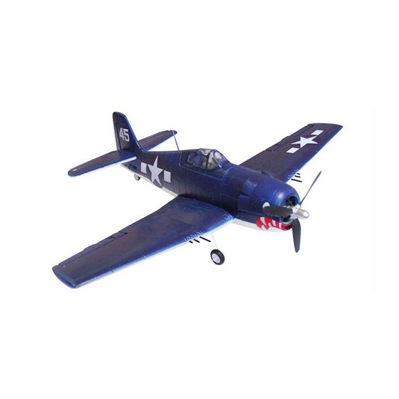
F6F HELLCAT
VQ No: VQA120
Instruction manual / Montageanleitung
SPECIFICATIONS
Wingspan:......................................1535mm
Length:...........................................1130mm
Electric Motor:.....................See next pager
Glow Engine:.................... .46 2-T / .70 4-T
RTF Weight: 3.5Kg (will vary with equipment
use)
Radio:....................8 Channel / 8-9 Servos
Function: Ailerons-Elevator-Rudder-Throttle
Flaps-Optional Retractable Landing Gear.
WARNING! This radio controlled model is NOT a toy. If modified or flown carelessly it could go out of controll and
cause serious human injury or property damage. Before flying your airplane, ensure the air field is spacious enough.
Always fly it outdoors in safe areas and seek professional advice if you are unexperienced.
ACHTUNG! Dieses ferngesteuerte Modell ist KEIN Spielzeug! Es ist für fortgeschrittene Modellflugpiloten bestimmt,
die ausreichende Erfahrung im Umgang mit derartigen Modellen besitzen. Bei unsachgemässer Verwendung kann
hoher Personen- und/oder Sachschaden entstehen. Fragen Sie in einem Modellbauverein in Ihrer Nähe um
professionelle Unterstätzung, wenn Sie Hilfe im Bau und Betrieb benötigen. Der Zusammenbau dieses Modells ist
durch die vielen Abbildungen selbsterklärend und ist für fortgeschrittene, erfahrene Modellbauer bestimmt.
Radio control model / Flugmodel
U.S NAVY FIGHTER
ALL BALSA, PLYWOOD CONSTRUCTION AND ALMOST READY TO FLY
TECHNISCHE DATEN
Spannweite:...................................1535mm
Lange:............................................1130mm
Elektroantrieb.............(siehe nächste Seite)
Verbrennerantrieb:...............7.45cc - 11.5cc
Fluggewicht:.......................................3.5Kg
Fernsteuerung..........8 Kanal / 8-9 Servos
Advertisement
Table of Contents

Subscribe to Our Youtube Channel
Related Manuals for VQ Models F6F HELLCAT


Summary of Contents for VQ Models F6F HELLCAT
- Page 1 Radio control model / Flugmodel U.S NAVY FIGHTER F6F HELLCAT VQ No: VQA120 ALL BALSA, PLYWOOD CONSTRUCTION AND ALMOST READY TO FLY Instruction manual / Montageanleitung TECHNISCHE DATEN SPECIFICATIONS Wingspan:........1535mm Spannweite:........1535mm Length:...........1130mm Lange:..........1130mm Electric Motor:.....See next pager Elektroantrieb.....(siehe nächste Seite) Glow Engine:....
- Page 2 REQUIRED FOR OPERATION (Purchase separately) 10.5x6 for .40 - 2 cycle engine 11x6 for .46 - 2 cycle engine 12x6 for .60 - 4 cycle engine Extension cord for aileron servos: 50cm(x2) 12x7 for .70 - 4 cycle engine Extension cord for flap servos: 50cm(x4) 13x7 - 13x8 for electric motor Extension cord for retract servos:...
-
Page 3: Engine Mount
1- ENGINE MOUNT Attach the engine mount beams onto the fire-wall so the distance between of two engine mount beams is “A”,and B=B’ as show. Secure the engine mount beams onto the fire-wall with litter CA glue (1B) ! Align the mark on both engine mount Push left (or right) the magnetic fuel tank hatch beams with the mark on the fuselage and full it out of the fuselage. - Page 4 2- ENGINE ! Engine thrust on balk head is already adjust at factory 106-108mm FUSELAGE C=106-108mm SIDE-VIEW Position the engine to the engine mounts so the distance from the prop hub to the fire-wall is 106-108mm. Mark the engine mounting plate where the four holes are to be drilled (8B) 3x25mm screw ..4 Washer...
-
Page 5: Electric Motor
3- ELECTRIC MOTOR ! Align the mark on wooden motor mounting plate with the mark on the fire-wall. Using a aluminum motor mounting plate as a template, mark the plywood motor mounting plate where the four holes are to be drilled. Remove the aluminum motor mounting plate and drill a 1/8”(3mm) hole through the plywood at each of the four marks... -
Page 6: Fixed Gear
4- FIXED GEAR Remove the nylon gear Reposition the nylon gear Slide the landing gear onto the Using the nylon gear strap strap and drill a 2mm hole strap and secure them in plywood gear mount and push as a template, mark the at each of the four marks place using four 3x12mm the landing gear as shown. - Page 7 5- FIXED GEAR Continued Attach the fixed gear onto the wing and mark the gear mount on the wing where the four holes to be drill. Remove the fixed gear and drill a 2mm hole at each of the four marks marked. CENTER WING - BOTTOM VIEW Attach the fixed gear onto the wing and mark the gear mount on the wing where the four holes to be drill.
- Page 8 6- FIXED GEAR Continued Slide the two plastic gear door mounts onto each landing gear. Secure the plastic gear door Slide the wheels and 4mm collar onto the mount in place using the landing gears. Plastic gear door mount 3mm screw set. Attach the plastic gear door to the plywood gear door.
- Page 9 Attach the electric retract gear onto the wing and mark 7- ELECTRIC RETRACT the gear mount on the wing where the four holes to be drill. Remove the electric retract gear and drill a 2mm hole at each of the four marks marked. Reposition the electric retract gear onto the wing and secure it in place using there 3x20mm and one 3x12mm screw as show.
- Page 10 8- ELECTRIC RETRACT Continued Slide the wheel and collar onto the wheel axle. Connect the electric retract with the radio to check the position of the wheel when the electric retract in retracted position. Ensure smooth non-binding movement. Cut the landing gear excess. Roll the towel paper around the landing gear at here before glue, because if the CA glue...
- Page 11 9- SERVO - CONTROL HORN (CENTER WING) Flap push-rod 2 mm Flap servo Secure the plastic control horn in place using the thin CA glue. Wooden dowel Push the wooden dowel to the hole on the rib as show Ensure that the dowel is rectangular with the rib. Secure it in place using the thin CA glue.
- Page 12 10- SERVO - CONTROL HORN (RIGHT AND LEFT WING) Assemble left and right wings the same way. Cut away only the covering Cut away only the covering BOTTOM VIEW Flap push-rod 2 mm Flap servo Steel clevis ..2 Aileron push rod (2mm) ..2 Flap push rod (1.2mm) ....2...
- Page 13 11- JOINING THE WINGS...
- Page 14 12- JOINING THE WINGS Continued...
-
Page 15: Horizontal Stabilizer
13- HORIZONTAL STABILIZER Using a sharp hobby knife, carefully cut away the covering around of all slots for the horizontal stabilizer and vertical fin installation. Pull the left and right elevator out of the horizontal stabilizer. Push the horizontal stabilizer into the slot on the fuselage as show. - Page 16 14- HORIZONTAL AND VERTICAL STABILIZER Apply thin CA glue into the slot where Apply CA glue the fuselage meet the horizontal stabilizer. both sides. (thin CA) B=B’ B’ Install the horizontal stabilizer onto the fuselage and adjust the alignment as described in steep 13B. Note: it is important to ensure that the horizontal stabilizer is also level in regards to the fuselage.
-
Page 17: Vertical Stabilizer
15- VERTICAL STABILIZER Remove the vertical stabilizer from the fuselage. Using s sharp hobby knife, carefully cut away the covering below the lines which were drawn in the previous steep. Do not cut into the woods as this will affect the structural integrity of thestabilizer (12C). 90 degree triangle Apply thin CA... - Page 18 16- ELEVATOR CONTROL HORN Push the elevator push-rod with clevis into the black nylon push-rod guide. Using the plastic control horn as a template, mark the mounting hole positions, where the elevator clevis meet the rudder control horn with a felt tipped or a pencil. Move the plastic control horn and drill two 2mm holes through the elevator.
-
Page 19: Tail Wheel
18- TAIL WHEEL Insert the tail wheel push-rod into the hole on the tail gear control horn (as show). Install the tail wheel control horn in place. Instal the tail wheel gear in place. Secure the tail wheel control horn in place using a 2mm screw set, ensure smooth non-binding movement. - Page 20 20- LINKAGES Rudder pushrod 3mm set Screw Tail wheel pushrod Rudder pusshrod D=5/64”(2mm) Tail wheel pushrod 2 mm D=.050”(1.2mm) RUDDER SERVO FUSELAGE - BOTTOM VIEW Elevator pushrod 3mm set Screw Throttle push-rod 2 mm Elevator pushrod D=5/64”(2mm) 2 mm Throttle servo In case of Glow engine using ELEVATOR SERVO Steel clevis...
- Page 21 21- COWLING USS PRINCETON VF-27 USS PRINCETON VF-27 Note: Cut out the stickers and apply them in the proper area. Do not peel the backing paper off all at once. Peel off one corner of the backing and cut off with scissors. Arrange sticker on model and when satisfied adhere the corner without backing.
-
Page 22: Installing The Wing
22- INSTALLING THE WING... -
Page 23: Installing The Bottom Cover
23- INSTALLING THE BOTTOM COVER... -
Page 24: Control Surface
22-BALANCE Note: Adjust the location of the battery pack to achieve this C.G location. (92 ~ 96mm) DO NOT try to fly an out-of balance model! Wing center section 23-CONTROL SURFACE (15mm) (10mm) (10mm) (15mm) ELEVATOR STROKE AILERON STROKE (25mm) (25mm) RUDDER STROKE (35mm)
Need help?
Do you have a question about the F6F HELLCAT and is the answer not in the manual?
Questions and answers