Table of Contents
Advertisement
Quick Links
Radio control model / Flugmodel
Instruction manual / Montageanleitung
SPECIFICATIONS
Wingspan
Length
Electric Motor
Glow Engine
Radio
TECHNISCHE DATEN
Spannweiter
Lange
Elektroantrieb
Verbrennerantrieb
Fernsteuerung
WARNING! This radio controlled model is NOT a toy. If modified or flown carelessly it could go out of controll and
cause serious human injury or property damage. Before flying your airplane, ensure the air field is spacious enough.
Always fly it outdoors in safe areas and seek professional advice if you are unexperienced.
ACHTUNG! Dieses ferngesteuerte Modell ist KEIN Spielzeug! Es ist für fortgeschrittene Modellflugpiloten bestimmt,
die ausreichende Erfahrung im Umgang mit derartigen Modellen besitzen Bei unsachgemäßer Verwendung kann
hoher Personen- und/oder Sachschaden entstehen. Fragen Sie in einem Modellbauverein in Ihrer Nähe um
professionelle Unterstützung, wenn Sie Hilfe im Bau und Betrieb benötigen. Der Zusammenbau dieses Modells ist
durch die vielen Abbildungen selbsterklärend und ist für fortgeschrittene, erfahrene Modellbauer bestimmt.
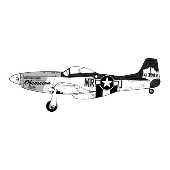
P51D
US.ARMY P51D 5NA
SERIAL NO AAF31 36542
for
GUNNIN'
GLORY
CREW WEIGHT 300LBS
ALL BALSA, PLYWOOD CONSTRUCTION AND ALMOST READY TO FLY
1580mm
1180mm
870 Watt
.46 2-T / .70 4-T
6 Channel / 7 Servos
1580mm
1180mm
870 Watt
7.5cc 2-T / 11cc 4-T
6 Kanal / 7 Servos
VQA08GY
(Obsession)
N151MW
VQA07
L (Lady Alice)
23580
VQA07S
(Gunnin for glory)
Advertisement
Table of Contents

Related Manuals for VQ Models P51D MUSTANG


Summary of Contents for VQ Models P51D MUSTANG
- Page 1 Radio control model / Flugmodel VQA08GY (Obsession) N151MW VQA07 L (Lady Alice) 23580 P51D US.ARMY P51D 5NA SERIAL NO AAF31 36542 GUNNIN’ GLORY CREW WEIGHT 300LBS VQA07S (Gunnin for glory) ALL BALSA, PLYWOOD CONSTRUCTION AND ALMOST READY TO FLY Instruction manual / Montageanleitung SPECIFICATIONS Wingspan 1580mm...
- Page 2 SAFETY NOTES BEFORE ASSEMBLING This model is highly pre-fabricated and can be built in a very short time. However, the work which you have to carry out is important and must be done carefully. The model will only be strong and fly well if you complete your tasks competently - so please work slowly, accurately and check every joints, maybe apply more glue to be safe.
- Page 3 P-51D Mustang 1- Servo & Control horn 1-Depending on the position of the linkage, determine the location of aileron control horn. The horn holes must be perfectly aligned with the axis of articulation. Control horn Alignment 2-Mark the position of the “foot” of the horn on the aileron. Then, with the drill, make the 2 holes. Thin CA 3-Install the aileron control horn as shown.
-
Page 4: Joining The Wing
P-51D Mustang 2- Aileron and flap linkages Threadlocker -Switch on the radio (trims centered) Then mount the ailerons servo horn In neutral position. -The servo horn should be Perpendicular to the servo 175mm rod with clevis one end ..4 2mm connector ..4 3- Joining the wing Before gluing:... -
Page 5: Fixed Gear
P-51 Dago Red 4- Joining the wing Continued Carefully slide the wing halves together, ensuring that they are accurately aligned. Firmly press the two halves together, allowing the excess epoxy to run out. Note: The two wing halves roots must fit together perfectly. Clear off the excess epoxy. -
Page 6: Fixed Gear Installation
P-51D Mustang 6- Fixed gear installation 3x12mm screw ..8 3x12mm screw ..2 ...2... -
Page 7: Main Wheel
P-51D Mustang 7- Main wheel 1.5mm 2mm screw ..4 Note: you can use 2x8mm self tapping screws to fix the plastic cover if possible late you can use retract landing gear... -
Page 8: Air Scoop
P-51D Mustang 8- Air scoop 6x40mm nylon bolt ..2 Using the plastic air scoop and wing shield as a template, with the pencil, trace around the outside edge of the air scoop and wing shield. then remove it Using a sharp hobby knife, cut away the covering inside the line, not to cut into the wood. - Page 9 P-51D Mustang 9- Air scoop Continued Thin CA Thin CA Note: This rubber “O” ring keeps the plastic bolt from coming out of the wing. Rubber “O” ring 6x40 plastic bolt or rubber band WING Plastic air scoop Plastic cover Plastic mount nut Wing bolt mount (Ply wood)
-
Page 10: Horizontal Stabilizer
P-51D Mustang 10- Horizontal stabilizer Cut away only the covering both the right and left side When you insert the horizontal stabilizer into the slot on the fuselage, if necessary, use sander to widen the slot to make this easier. Step 10:1 Trial fit the horizontal stabilizer in place . -
Page 11: Vertical Stabilizer
P-51D Mustang 11- Vertical stabilizer Step 11:1 Trial fit the vertical stabilizer in place . C’ Step 11:2 C = C’ When you are satisfied with the alignment, use a pencil to trace around the right and left of the stabilizer where the vertical stabilizer meet the fuselage. -
Page 12: Tail Wheel
12- Elevator & rudder P-51D Mustang Securely glue together. If coming off during flight, you lose control of your air plane. 3/8 in. (9.5mm) push the elevator and its hinges into the hinge slots in the trailing edge of the horizontal stabilizer. There should be a minimal hinge gap. - Page 13 P-51D Mustang 14- Engine mount & Engine ! Align the mark on both engine mount beams with the mark on the firewall. B’ FRONT-VIEW B=B’ Attach the engine mount beams onto the fire-wall so the distance between of two engine mount beams is “A”,and B=B’ as show. Secure the engine mount beams onto the fire-wall with litter CA glue.
-
Page 14: Electric Motor
P-51D Mustang 15- Fuel tank Blow To muffler Water Filler tube Rubber stopper To engine Checking for leaks - block the vents and blow into the feed. if in doubt submersing the tank in a blow of water will show up any problems. - Page 15 P-51D Mustang 17- Electric motor Continued Remove the wooden motor mounting plate and drill a 5mm hole through the fire-wall at each of the four marks marked . 3mm hex bolt / nut...4 Step 17:1 Secure the Motor to the wooden motor mounting plate using the four 3mm hex bolts.
- Page 16 P-51D Mustang 19- Elevator & Rudder linkages Insert the Li-po battery tray into the fuselage as shown in the figure. Secure it in place with CA glue or Epoxy glue. Li-po battery 2x100mm pushrod .....2 Tail wheel push-rod 1.2x800mm pushrod .....1 Rudder push-rod 2x950mm pushrod and clevis...
- Page 17 P-51D Mustang 20- Cowling Attach the board or transparent plastic on the side of the fuselage with the adhesive tape as show. Using a pencil or felt tipped pen trace around the engine head where it meet the cowl. Cut the opening the board or transparent plastic for the engine head as marked before.
- Page 18 P-51D Mustang 21- Sticker VQA08GY (Obsession) Fuel cap Note: Cut out the stickers and apply them in the proper area. Do not peel the backing paper off all at once. Peel off one corner of the backing and cut off with scissors. Arrange sticker on model and when satisfied adhere the corner without backing.
- Page 19 VQA07HJ “ Happy Jack” Fuel cap Sticker Sticker Sticker P-51D “HAPPY JACK’S” VQ MODELS P-51D HAPPY JACK 23- Balance THE CENTER OF GRAVITY IS LOCATED 132mm BACK FROM THE LEADING EDGE OF THE WING, AT THE FUSELAGE. BALANCE A PLANE UPSIDE DOWN WITH THE FUEL TANK EMPTY.
-
Page 20: Control Surface
P-51D Mustang 24- Balance continued 1- Mount the wing to the fuselage. Using a couple of pieces of masking tape, place them on the top side of the wing (132mm) back from the leading edge, at the fuselage sides. 2- Lift the airplane. Place your fingers on the masking tape and carefully lift the plane. 3- If the nose of the plane falls, the plane is heavy nose.
Need help?
Do you have a question about the P51D MUSTANG and is the answer not in the manual?
Questions and answers